
Related Manuals for Ista ultego III smart plus


Summary of Contents for Ista ultego III smart plus
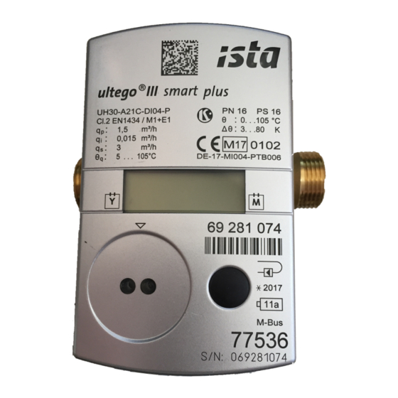
- Page 1 Ultrasonic heating and cooling meter ultego III smart plus Residential ultego III smart plus Technical description 32 22 101 001 a Date: 07.04.2017 ista Middle East FZE...
- Page 2 Outstanding features 2/26 Outstanding features Meter for measurement of flow and energy in a heat or cold circuit with water using the ultra- sonic principle. Important properties are: Non-wearing due to non-moving parts Compact, space-saving design Robust all-metal measuring section ...
-
Page 3: Table Of Contents
Contents 3/26 Contents General notes ____________________________________________________________ 4 Other available documents __________________________________________________ 4 Safety information ________________________________________________________ 5 Technical data ___________________________________________________________ 7 Dimensions (qp 0,6 – 2,5 m³/h) _______________________________________________ 8 Installation _____________________________________________________________ 10 Installation notes _________________________________________________________ 10 Examples of installation ____________________________________________________ 11 Installation notes for sensor adapter set (sensors directly immersed) ________________ 12 Installation for cooling metering ___________________________________________ 12 Dimension of electronic unit _______________________________________________ 13... -
Page 4: General Notes
General notes 4/26 General notes Note In the following text, the term meter refers to heat meter and cooling meter, unless they are otherwise differentiated. The meter is used as a meter for heating or cooling consumption measure- ment in systems with water. The meter consists of a volume measurement unit, two fixed temperature sen- sors and an electronic unit that calculates the energy consumption from the volume and temperature difference. -
Page 5: Safety Information
Safety information 5/26 Safety information The meter may only be used in building service engineering systems and only for the applications described. The local regulations (installation etc.) must be adhered to. Adhere to the operating conditions according to the dial plate during use. - Page 6 Safety information 6/26 You can return the lithium batteries to the manufacturer for appropriate disposal following use. When shipping please ob- serve legal regulations, in particular, those governing the label- ling and packaging of hazardous goods. Do not open the batteries. Do not bring batteries into contact with water or expose to temperatures above 80 °C.
-
Page 7: Technical Data
Technical data 7/26 Technical data General Measuring accuracy Class 2 or 3 (EN 1434) Environment class A (EN 1434) for indoor installation Mechanical class M1 / M2 *) Electromagnetic class E1 *) *) acc. to 2014/32/EU Directive on Measuring Instruments Ambient humidity <... -
Page 8: Dimensions (Qp 0,6 - 2,5 M³/H)
Technical data 8/26 mbar 15.5 x 13.5 x 12.0 22.5 x 18.5 x 11.3 15.5 x 13.5 x 12.0 15.5 x 13.5 x 12.0 22.5 x 18.5 x 11.3 15.5 x 13.5 x 12.0 22.5 x 18.5 x 11.3 Tolerance of pressure loss: +/- 5% Dimensions (qp 0.6 –... - Page 9 Technical data 9/26 Abb. 3: Overview dimensions overall length 190 mm (thread) Overall Order- length m³/h UH30-x05 UH30-x06 UH30-x07 UH30-x09 UH30-x21 UH30-x22 UH30-x23 UH30-x25 UH30-x26 UH30-x27 UH30-x36 UH30-x37 UH30-x38 UH30-x40...
-
Page 10: Installation
Installation 10/26 Installation To install the meter proceed as follows: Determine the place of installation in line with the inscription on the meter. Note: For a heat meter the mounting place of the cold side is equivalent to return and the mounting place hot side is equiv- alent to flow Note: For a cooling meter the mounting place of the hot side is... -
Page 11: Examples Of Installation
Installation 11/26 Examples of installation You can install the meter in any position e.g. vertically or horizontally. In order to avoid accumulation of air and disruption in operation, fit the meter in a verti- cal installation position and not in the uppermost area of a pipeline. This position is not permitted for cold meters and in cases where moisture can enter the electronic unit due to conden-... -
Page 12: Installation Notes For Sensor Adapter Set (Sensors Directly Immersed)
Installation 12/26 Installation notes for sensor adapter set (sensors directly immersed) A mounting set is included for meters with 5.2 × 45 mm temperature sensor. With this you can fit the temperature sensor directly immersed into an insert or a ball valve for example. Install with O-ring at the point of installation with the fit-up aid/pen provided. -
Page 13: Dimension Of Electronic Unit
Dimension of electronic unit 13/26 Dimension of electronic unit Fig. 10: Electronic unit Fig. 11: Wall adapter (view from above and side) Fig. 12: Maximum screw head height (if using the wall bracket) - Page 14 Dimension of electronic unit 14/26 Fig. 13: Wall mounting...
-
Page 15: Operating Elements
Operating elements 15/26 Operating elements Fig. 14: LCD Description Identification previous year value Previous year value Maxima Previous month value Identification previous month value Activity display at flow Calibrated value 6.1 Displaying current meter status The meter displays the current meter status in kWh, MWh, MJ or GJ. Note: In order to prevent reading errors, the decimal places of the values displayed are marked with a frame. -
Page 16: Current Values "Loop 1
Operating elements 16/26 Current values “LOOP 1” Current values Current flow Current heat power Current temperature hot side / cold side alternating in 2 s cycles Temperature difference Operating time Missing time Time with flow Previous month's values “LOOP 2“ Monthly values Log date Energy quantity and volume on set day... -
Page 17: General / Communication "Loop 3
Operating elements 17/26 General / Communication “LOOP 3“ General / Communication Device number, 7-digit Optional interface Primary address (only for M-Bus) Secondary address 7-digit - for M-Bus Yearly set day Monthly set day Firmware version CRC-Code Other “LOOP 4“ Other Date Time Code entry for test / para operation... -
Page 18: Resolution Of The Display
Resolution of the display 18/26 Resolution of the display 1 kWh 0.001 MWh 1 MJ 0.001 GJ m³/h 0.001 m³/h m³ 0.01 m³ Nominal flow rate in m³/h Power supply The meter is according to the configuration equipped with 1 – 3 lithium batter- ies. -
Page 19: Communication
Communication 19/26 Communication Electronic unit interfaces The meter is equipped with an optical interface in accordance with EN 62056- 21:2002 as standard. Note: You can find further information in their respective documen- tation. M-Bus If the meter is equipped with the option M-Bus, it is supplied with a 2-wire ca- ble which you can extend by fitting a junction box. -
Page 20: Wireless M-Bus
Communication 20/26 Wireless M-Bus The wireless M-Bus function enables the meter to communicate with a sta- tionary unit (e. g. radio concentrator, smartphone with radio adapter) using 868 MHz radio frequency (unlicensed). The function supports the OMS -compliant data transfer. Standard Open Metering System Specification (Issue 3.0.1);... -
Page 21: Data Telegram F002 - Mobile Data Reading
Communication 21/26 Data telegram F001 – mobile data reading (sending interval 20 sec, battery life- time 6 years) Following data are available by default for data reading: Current energy Current volume Energy: previous month on reference date ... -
Page 22: Error Codes
Error codes 22/26 Error codes The meter continuously runs a self-diagnosis and can thus recognize and dis- play various installation or error messages. Error Error Service guidelines code Check flow or installation direction; Incorrect flow direction correct if necessary if necessary in exchange with: Check installation point of the tem- DIFF Negative temperature dif-... -
Page 23: Order Codes (Type Number Key)
Order codes (type number key) 23/26 Order codes (type number key) Order codes for label plate data Norway (Norwegian) Poland (Polish) 1. Type of meter and mounting location Code Sweden (Swedish) Heat meter for mounting place cold side Slovenia (Slovenian) Heat meter for mounting place hot side 5. -
Page 24: Additional Ordering Information For Wm-Bus
Additional ordering information for wM-Bus 24/26 Additional ordering information for wM-Bus Note: The battery life time always depends on the meter configuration (measuring interval) and on the data telegram length, encryption (with / without) and sending interval (mobile / stationary)! All these configurations can be changed with the service software! Note: Data in the radio module is updated every 15 minutes independent of the sending inter- val. -
Page 25: Pressure Loss
Pressure loss 25/26 Pressure loss Nominal flowrate Overall Pressure Kv-Factor Graph in Connection at Δp 1 bar length loss at qp diagram G / DN mbar 110, 190 130, 190 The indicated pressure loss of a flow sensor is at nominal flowrate qp. With the Kv-Factor, which defines the flow rate at a pressure loss of 1 bar, the pressure loss at any given flow rate can be calculated: ∆��... - Page 26 Middle East FZE Dubai Branch P.O. Box 502302 Dubai. U.A.E.
Need help?
Do you have a question about the ultego III smart plus and is the answer not in the manual?
Questions and answers