Table of Contents
Advertisement
Available languages
Available languages
Quick Links
BEDIENUNGSANLEITUNG
USER'S MANUAL
MODE D'EMPLOI
MANUAL DEL USUARIO
EX-840
Club-Mixer
©
Für weiteren Gebrauch aufbewahren!
Copyright
Keep this manual for future needs!
Nachdruck verboten!
Gardez ce mode d'emploi pour des
Reproduction prohibited!
utilisations ultérieures!
Réproduction interdit!
Guarde este manual para posteriores usos.
Prohibida toda reproducción.
Advertisement
Table of Contents

Subscribe to Our Youtube Channel
Related Manuals for Omnitronic EX-840 Club-Mixer


Summary of Contents for Omnitronic EX-840 Club-Mixer
- Page 1 BEDIENUNGSANLEITUNG USER'S MANUAL MODE D'EMPLOI MANUAL DEL USUARIO EX-840 Club-Mixer © Für weiteren Gebrauch aufbewahren! Copyright Keep this manual for future needs! Nachdruck verboten! Gardez ce mode d’emploi pour des Reproduction prohibited! utilisations ultérieures! Réproduction interdit! Guarde este manual para posteriores usos. Prohibida toda reproducción.
-
Page 6: Table Of Contents
MULTI-LANGUAGE-INSTRUCTIONS Inhaltsverzeichnis Table of contents Sommaire Contenido 1. EINFÜHRUNG............................... 8 1.1 Features ..............................8 2. SICHERHEITSHINWEISE..........................9 3. BESTIMMUNGSGEMÄßE VERWENDUNG....................10 4. ANSCHLÜSSE ............................11 5. GERÄTEÜBERSICHT..........................13 5.1 Vorderseite............................. 13 5.2 Rückseite ............................... 15 6. BEDIENUNG ............................... 16 7. PROBLEMBEHEBUNG ..........................16 8. - Page 7 You can find the latest update of this user manual in the Internet under: Vous pouvez trouvez la dernière version de ce mode d'emploi dans l'Internet sous: Vd. puede encontrar la versión más reciente de este manual en el Internet bajo: www.omnitronic.com 7/47 10007050_V_1_1.DOC...
-
Page 8: Einführung
- sich die letzte Version der Anleitung im Internet herunter laden 1. EINFÜHRUNG Wir freuen uns, dass Sie sich für einen OMNITRONIC EX-840 Club-Mixer entschieden haben. Wenn Sie nachfolgende Hinweise beachten, sind wir sicher, dass Sie lange Zeit Freude an Ihrem Kauf haben werden. -
Page 9: Sicherheitshinweise
(mono) • Ausgangssignal über Masterfader (Master 1) oder Master-Regler (Master 2) einstellbar • Separat regelbarer Monitor-Ausgang (DJ-Booth) zum Anschluss von Aktiv-Boxen oder einer weiteren Endstufe • 2 Master-Out, Booth-Out und Rec-Out über je 2 Cinch-Buchsen • Zusätzlicher Master 1 Ausgang über symmetrische XLR-Einbaustecker •... -
Page 10: Bestimmungsgemäße Verwendung
Staub kann die Isolation reduzieren, was zu tödlichen Stromschlägen führen kann. Stärkere Verschmut- zungen im und am Gerät dürfen nur von einem Fachmann beseitigt werden. Es dürfen unter keinen Umständen Flüssigkeiten aller Art in Steckdosen, Steckverbindungen oder in irgendwelche Geräteöffnungen oder Geräteritzen eindringen. Besteht der Verdacht, dass - auch nur minimale - Flüssigkeit in das Gerät eingedrungen sein könnte, muss das Gerät sofort allpolig vom Netz getrennt werden. -
Page 11: Anschlüsse
Wird das Gerät anders verwendet als in dieser Bedienungsanleitung beschrieben, kann dies zu Schäden am Produkt führen und der Garantieanspruch erlischt. Außerdem ist jede andere Verwendung mit Gefahren, wie z. B. Kurzschluss, Brand, elektrischem Schlag, etc. verbunden. 4. ANSCHLÜSSE • Stellen Sie das Gerät auf einer ebenen Fläche auf. •... - Page 12 Belegung symmetrische XLR-Einbaubuchse: Belegung symmetrischer Klinkenstecker: • Außerdem verfügt das EX-840 über eine MIC 1-Klinkenbuchse an der Geräterückseite. Der Mikrofonpegel (MIC 1) lässt sich über Kanalfader 1 einstellen. Vergewissern Sie sich, dass der LINE 1/MIC 1-Schalter auf MIC 1 steht. •...
-
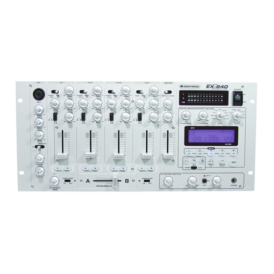
Page 13: Geräteübersicht
5. GERÄTEÜBERSICHT 5.1 Vorderseite (1) PHONO / LINE / AUX-SCHALTER Zur Auswahl der entsprechenden Signalquelle. (2) GAIN-REGLER Mit dem GAIN-Reger können Sie die Signalstärke des Eingangssignals einstellen. (3) CUE-TASTE Mit den CUE-Tasten bestimmen Sie, welcher Kanal vorgehört wird. (4) TREBLE-REGLER Mit dem TREBLE-REGLER können Sie die Höhen des Eingangssignals am jeweiligen Kanal verstärken bzw. - Page 14 (14) MIDDLE-REGLER Mit dem MIDDLE-Regler können Sie die Mitten des Mikrofonsignals verstärken bzw. zurücknehmen. (15) BASS-REGLER Mit dem BASS- Regler können Sie die Bässe des Mikrofonsignals verstärken bzw. zurücknehmen. (16) TALKOVER-WAHLSCHALTER Der dreistufige Wahlschalter hat folgende Funktionen: OFF: Mikrofon ist abgeschaltet. MIC ON: Das Mikrofon ist aktiviert.
-
Page 15: Rückseite
verändern. Befindet sich der CUE MIXING-Fader in der Mittelstellung, hören Sie sowohl das angewählte CUE-Signal als auch das Ausgangssignal. (37) CUE SPLIT/CUE MIX-TASTE Bei der Cue Split Funktion (Taste gedrückt) liegt auf einer Seite des Kopfhörers das Cue-Signal und auf der anderen Seite das Ausgangssignal an. -
Page 16: Bedienung
Stecken Sie hier die Netzleitung ein. 6. BEDIENUNG Schalten Sie das Gerät über den Netzschalter ein. Sobald Audio-Signale anliegen, wird der Signalpegel der Audio-Quelle auf dem Display angezeigt. Der Eingangssignalpegel lässt sich über den jeweiligen Gain-Regler einstellen. 7. PROBLEMBEHEBUNG PROBLEM: URSACHE: LÖSUNG: Gerät lässt sich nicht... -
Page 17: Reinigung Und Wartung
9. REINIGUNG UND WARTUNG LEBENSGEFAHR! Vor Wartungsarbeiten unbedingt allpolig vom Netz trennen! Das Gerät sollte regelmäßig von Verunreinigungen wie Staub usw. gereinigt werden. Verwenden Sie zur Reinigung ein fusselfreies, angefeuchtetes Tuch. Auf keinen Fall Alkohol oder irgendwelche Lösungsmittel zur Reinigung verwenden! Im Geräteinneren befinden sich keine zu wartenden Teile. -
Page 18: Technische Daten
10. TECHNISCHE DATEN Spannungsversorgung: 115/230 V AC, 50/60 Hz ~ Gesamtanschlusswert: 35 W Eingänge: 3 Phono, 4 Line, 3 Mic Eingangsempfindlichkeit: Mikrofon 1: 1,7 mV RMS, 2,2 kOhm Mikrofon 2 & 3: 1,7 mV RMS, 3 kOhm Phono: 3,4 mV RMS, 47 kOhm Line: 340 mV RMS, 20 kOhms Ausgangsspannung:... -
Page 19: Introduction
- download the latest version of the user manual from the Internet 1. INTRODUCTION Thank you for having chosen an OMNITRONIC EX-840. If you follow the instructions given in this manual, we can assure you that you will enjoy this device for many years. -
Page 20: Safety Instructions
amplifier • 2 Master-Out, Booth-Out and Rec-Out via 2 RCA-sockets each • Additional Master 1 output via balanced XLR-connectors • Total output level of Master 1 adjustable via Level-control on the rearpanel • Rec-Out independent from Master-level for records with static level • High-grade discotheque-mixer with a convincing sound 2. -
Page 21: Operating Determinations
If the power plug or the device is dusty, the device must be taken out of operation, disconnected and then be cleaned with a dry cloth. Dust can reduce the insulation which may lead to mortal electrical shock. More severe dirt in and at the device should only be removed by a specialist. There must never enter any liquid into power outlets, extension cords or any holes in the housing of the device. -
Page 22: Connections
4. CONNECTIONS • Install the device on a plane surface. • Make sure that the power switch is set to OFF. Before you connect the devices, all units have to be switched off. • In order to obtain highest sound quality, only use high-quality cables for connecting the devices. Make sure that the cables are properly fixed. -
Page 23: Description Of The Device
• Additionally, the EX-840 features one more ¼" Mic 1 jack plug on the rearpanel. You can adjust the microphone volume using the CH-1 fader. Make sure that the LINE 1/MIC 1-switch is set to MIC 1. • You can connect up to 3 record players using the PHONO 1 sockets, PHONO 2 sockets and PHONO 3 sockets on the rearpanel. - Page 24 (10) FADERSTART-BUTTON Press this button to activate the faderstart. (11) CROSSFADER Mixes the signals of one channel with another. If the crossfader is in the center-position, both channels can be heard at the same volume. (12) MIC 1-SOCKET You can connect microphones with XLR-plug or jack. (13) TREBLE-CONTROL Used to increase or lower the HIs of the microphone signal.
-
Page 25: Rearpanel
When you set the CUE MIXING-fader to PGM (CUE-buttons without function), you can cue the output signal of the mixer. When you set the CUE MIXING-fader to to the center position, you can cue both the channel-signal you selected and the output-signal. (37) CUE SPLIT/CUE MIX BUTTON Cue Split-function (button pressed): the Cue-signal is on the one side of the headphones and the output- signal on the other side. -
Page 26: Operation
6. OPERATION Switch the device on via the power switch. As soon as the Audio-signals are present the signal level is displayed. You can adjust the level of the input signals via the Gain-control. 7. PROBLEM CHART PROBLEM: CAUSE: REMEDY: No power. -
Page 27: Cleaning And Maintenance
9. CLEANING AND MAINTENANCE DANGER TO LIFE! Disconnect from mains before starting maintenance operation! We recommend a frequent cleaning of the device. Please use a soft lint-free and moistened cloth. Never use alcohol or solvents! There are no servicable parts inside the device. Maintenance and service operations are only to be carried out by authorized dealers. - Page 28 Bass: -30 dB to +10 dB, ± 1 dB at 70 Hz Tone control/Mic: Treble: ± 12, ± 2 dB at 13 KHz Middle: ± 12, ± 2 dB at 1 KHz Bass: ± 12, ± 2 dB at 70 Hz Cross Talk (Line): <...
-
Page 29: Introduction
- télécharger la version ultérieure du mode d'emploi d'Internet 1. INTRODUCTION Nous vous remercions d'avoir choisi un OMNITRONIC EX-840. Si vous respectez les instructions de service suivantes, vous allez profiter longtemps de votre achat. Sortez l'OMNITRONIC EX-840 de son emballage. -
Page 30: Instructions De Sécurité
Master-out (L/R) et signal Cue (mono) • Sortie master ajustable via fader master (Master 1) ou régulateur master (Master 2) • Sortie moniteur réglable (DJ-booth) de manière individuelle pour connecter des enceintes actives ou un amplificateur additionnel • 2 Master-Out, Booth-Out et Rec-Out grâce à 2 douilles cinch •... -
Page 31: Emploi Selon Les Prescriptions
endommagées, ce qui peut mener à des électrocutions mortelles. Si la fiche ou l'interrupteur de l'appareil ne sont pas accessibles, par exemple parce qu'ils sont enfermés par d'autres pièces, il faut procéder à une disjonction de tous les pôles du côté secteur. Si la fiche secteur ou l'appareil sont couverts de poussière, il faut le mettre hors service, il faut interrompre le circuit sur tous les pôles, et nettoyer l'appareil avec un chiffon sec. -
Page 32: Connexions
Ne nettoyez pas l'appareil avec des produits de nettoyages trop puissants ou abrasifs. Utilisez un chiffon doux, humide. Si vous deviez transporter l'appareil, utilisez l'emballage d'origine pour éviter tout dommage. Il est interdit de retirer le code barre de l'appareil. Ceci annulerait toute garantie. Si l'appareil est utilisé... -
Page 33: Description De L'appareil
Occupation de la douille XLR symétrique: Occupation du jack 6,35 mm symétrique: • Additionellement, le EX-840 dispose d'une douille MIC 1 au dos de l'appareil acceptant seulement des Jacks 6,3 mm. Vous pouvez contrôler le niveau du microphone MIC 1 avec le fader CH-1. Assurez-vous que le sélecteur LINE 1/MIC 1 est mis à... - Page 34 (1) SÉLECTEUR PHONO / LINE / AUX Pour niveler le niveau d’entrée de chaque canal. (2) RÉGULATEUR GAIN Pour régler le niveau d’entrée. (3) BOUTON CUE Avec les boutons CUE vous pouvez choisir les canaux à préécouter. (4) RÉGULATEUR TREBLE Pour élever ou réduire les aiguës.
-
Page 35: Dos De L'appareil
(26) REGULATEUR PARAMETER RATIO Grâce au régulateur Parameter Ratio, vous pouvez ajuster l'inténsité d'effet. (27) SELECTEUR INPUT SELECT Pour sélectionner la source désirée. (28) SELECTEUR EFFECTS SELECT Pour sélectionner L'effet désiré. (29) AFFICHAGE D'EFFETS (30) TOUCHES BEAT SYNC Grâce aux touches Beat Sync, vous pouvez ajuster les effets à la vitesse de la plage actuelle. (31) TOUCHES X-FADER EFFECTS (32) BOUTON EFFECT CUE Avec le bouton Effect Cue vous pouvez préécouter le canal d'effets. -
Page 36: Maniement
(45) ENTRÉES LINE 4 Prise d'entrée pour canal CH-4. (46) REC OUT Connectez votre appareil d'enregistrement ici. Le niveau de REC OUT n'est pas contrôlé avec le fader MASTER (47) ZONE OUT Pour connecter vos haute-parleurs moniteur actives ou un amplificateur supplémentaire. (48) MASTER OUT Pour connecter l’amplificateur principal. -
Page 37: Remplacement Du Crossfader
8. REMPLACEMENT DU CROSSFADER Procédez de la manière suivante: • Retirez la tête du fader. • Retirez les deux vis extérieurs à la plaque du fader. • Retirez maintenant le crossfader et débranchez. • Connectez le crossfader de rechange et fixez-le à la table de mixage. La plaque du crossfader de remplacement ne peut être utilisée pour l'édition de dessin. -
Page 38: Caractéristiques Techniques
10. CARACTERISTIQUES TECHNIQUES Alimentation: 115/230 V AC, 50/60 Hz ~ Puissance de rendement: 35 W Entrées: 3 phono, 4 line, 3 mic Tension minimum d'entrée: Microphone 1: 1,7 mV RMS, 2,2 kOhm Microphone 2 & 3: 1,7 mV RMS, 3 kOhm Phono: 3,4 mV RMS, 47 kOhm Line:... -
Page 39: Introducción
-pasar el manual a cada sucesivo poseedor o usuario del producto -descargar la última versión del manual del Internet 1. INTRODUCCIÓN Gracias por haber elegido un OMNITRONIC EX-840. Desembale su EX-840. Antes de la puesta en marcha inicial, por favor asegúrese de que no hay daños causados durante el transporte. -
Page 40: Instrucciones De Seguridad
el fader Master (Master 1) o control Master (Master 2) • Salida de monitor controlable separadamente (DJ- Booth) para conectar altavoces activos o un amplificador adicional • 2 salidas Master, salida Booth y salida Rec mediante dos casquillos cinch • Salida Master 1 adicional mediante conectores XLR simetricos • Salida Rec independiente del nivel Master para grabaciones con nivel estático •... -
Page 41: Instrucciones De Manejo
por un especialista si insulaciones están reducidos a causa del líquido. Insulaciones reducidos pueden causar un golpe eléctrico mortal. Piezas de todas formas deben nunca entrar en el aparato - especialmente piezas de metal. Cuando supone que piezas de metal pueden haber entrado en el aparato, desenchufe el aparato inmediatamente. Malfunciones o cortocircuitos pueden causar un golpe eléctrico mortal. - Page 42 Para conseguir la mayor calidad de sonido utilice únicamente cables de alta calidad para conectar los aparatos. Asegúrese de que los cables están fijados adecuadamente. Puede conectar hasta 3 a amplificadores al EX-840. Puede reglar la señal master 1 con el Masterfader 1 y el controlador "Balance".
-
Page 43: Vista General Del Aparato
Conecte su cassette, radio, CD-player o todas las otras señales de línea a los casquillos LINE del panel trasero. Las señales de línea pueden ser controladas sólo después de que ha conectado el interruptor PHONO/LINE a LINE. La señal es controlada entonces mediante los respectivos faders. Conectar el aparato a la red mediante el cable de alimentación incluído. - Page 44 (13) Regulador "Treble" Para ajustar los agudos del micrófono. (14) Regulador "Middle" Para ajustar los medios del micrófono. (15) Regulador "Bass" Para ajustar los graves del micrófono. (16) Selector de función “Talkover” Este selector tiene las funciones siguientes: OFF: el micrófono está desactivado. MIC ON: el micrófono está...
-
Page 45: Panel Trasero
(39) Casquillo de los auriculares Se utiliza para conectar los auriculares. Se puede utilizar auriculares desde 8 ohmios hasta 600 ohmios. 5.2 Panel trasero (40) Casquillo jack MIC 2 Conecte su micrófono con clavija jack 6,35 mm. (41) Casquillo jack MIC 3 Conecte su micrófono con clavija jack 6,35 mm. -
Page 46: Solución De Problemas
7. SOLUCIÓN DE PROBLEMAS PROBLEMA: CAUSA: SOLUCION: La alimentación no se conecta. • El cable de alimentación no está • Compruebe el cable de conexión y conectado. cables de extension. No hay sonido. • El interruptor PHONO/LINE/AUX • Pone el interruptor del canal respectivo no está... -
Page 47: Especificaciones Técnicas
10. ESPECIFICACIONES TÉCNICAS Alimentación: 115/230 V AC, 50/60 Hz ~ Consumo: 35 W Entradas: 3 phonos, 4 líneas, 3 mic Voltaje mínimo: Micrófono 1: 2 mV RMS, 1 kOhmios Micrófono 2 & 3: 1 mV RMS, 1 kOhmios Phono: 3,16 mV RMS, 47 kOhmios Line: 200 mV RMS, 10 kOhmios Tensión de salida:...
Need help?
Do you have a question about the EX-840 Club-Mixer and is the answer not in the manual?
Questions and answers