Advertisement
PUBLIC ADDRESS POWER AMPLIFIER ● QUANTUM POWER SERIES
Thank you
for choosing another quality product from Amperes Electronics.
Quantum QP2000 Series of power amplifiers are the latest generation of power packs that had been developed through years
of experience, countless feedbacks and limitless fine tuning of its predecessors, thus offering a new and unique audio amplifi-
cation product.
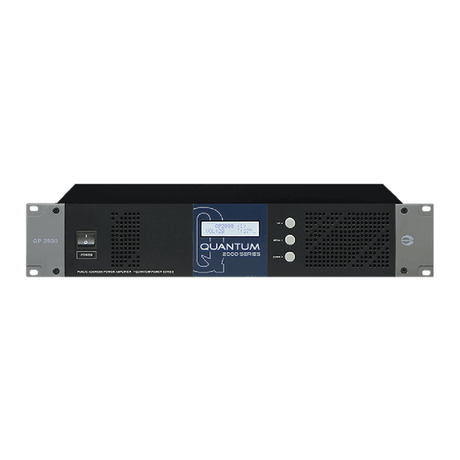
QP2000 series are available in the power range of 125, 250, 275 and 500W 100V line ratings with 2 hu height. Control parts had
been made contemporary with digital settings via front panel or through custom built software. Various and known protection
features are incorporated such as auto fault sensing (AFS), in built standby amplifier changeover, temperature sensing and
many more.
You shall be very certain that this is the final product you would ever search. We make it available without you paying high price
for a premium product that works exceeding your expectation.
VER 4 / 2015
Advertisement
Table of Contents

Related Manuals for Amperes Quantum Series


Summary of Contents for Amperes Quantum Series
- Page 1 PUBLIC ADDRESS POWER AMPLIFIER ● QUANTUM POWER SERIES Thank you for choosing another quality product from Amperes Electronics. Quantum QP2000 Series of power amplifiers are the latest generation of power packs that had been developed through years of experience, countless feedbacks and limitless fine tuning of its predecessors, thus offering a new and unique audio amplifi- cation product.
-
Page 2: Parts Identification
Parts Identification Front View PUBLIC ADDRESS POWER AMPLIFIER ● QUANTUM POWER SERIES Rear View 1. POWER SWITCH Mains ac power switch. The unit operates with 220 - 240V ac. 2. LCD DISPLAY 2 X 18 character LCD displaying units parameters and programming instructions. 3. -
Page 3: Ac Mains Input
Parts Identifications ( con’t ) 9. AC MAINS INPUT Operating voltage is 220 to 240V ac ; 50 hertz. Use suitable fuse for replacement. Recommended Fuse Replacements : QP2125 QP2250 QP2375 QP2500 6.3A 6.3A Slow blow fuse is recommended. 10. DC INPUT TERMINAL 24V DC back up supply from batteries are connected to these connectors. - Page 4 General Schematic Diagram An example of application with PM1120 PAGING MIC single source to amplifiers, with INPUTS line audio one unit being a standby unit. MX2222 Mixer For Uninterrupted Paging System Matrix application, please SELECT POWER SOURCE MASTER EXT INPUT TONE CTRL contact us for further details.
-
Page 5: Connecting The Unit
Connecting The Unit A connection diagram for basic installation with single input source from pre-amplifier mixer. 24V DC Audio from pre-amp 100V Line Out Fr Battery mixer ( balanced line ) To Zone Selector Bank note on the link connections for standby amplifier DUTY AMPLIFIER UNIT 100V... -
Page 6: Matrix Controller
Connecting The Unit - Matrix Paging AUDIO FROM MESSAGE PLAYER / RECORDER EP1200A AUDIO INPUTS FROM MXP2188 MATRIX CONTROLLER 24V DC ER1108 IN P U T 8 IN P U T 7 IN P U T 6 IN P U T 5 IN P U T 4 IN P U T 3 IN P U T 2... - Page 7 Connecting The Unit - Uninterrupted Paging PM SERIES PAGING MIC amp eres BGM Inputs MX2222 MIXER A U X AC 230V 50/60HZ Paging audio output BGM audio output Standby Standby Duty 1 Duty 1 Duty 2 Duty 2 BGM Output Paging Output ZS5602 SPEAKER ZONE SELECTOR...
-
Page 8: Setting The Unit
Setting The Unit Upon powering up the unit, the display shall appear as shown, Initialising and into ready mode. Displaying firmware version of Showing unit address in bracket, the unit volume level and temperature Menus available are for : To begin setting, press the MENU button. Use Next 1. - Page 9 Setting The Unit 2. CASCADE Setting the address is used only when all the amplifiers at to be linked to remote PC Select Sub Menu 2 for unit addressing for monitoring. Software is available free, but an USB-RS485 interface shall be required.
- Page 10 Setting The Unit 4. INFO Select Sub Menu 4 This menu provides information on various parameters such as input and output level. Output voltage from 100V line terminal For service purpose : the voltage prior to step up transformer Signal input value Output value in dB 5.
-
Page 11: Summary Of Features
Summary of Features Digital Setting for various parameters with LCD display Auto fault sensing ( AFS ) with fault contact Built in standby amplifier changeover RS485 interface for monitoring and remote setting Tone and bass controls Auto fan speed controls Thermal, fuse, output short circuit protections High efficiency with low current consumption Remote monitoring through PMX II LAN via iPX5500 Comm. -
Page 12: Warranty Conditions
Only Amperes Electronics Service Centres are allowed to make warranty repairs : a list of Amperes Electronics Service Centres may be asked for by the purchaser or send directly to Amperes Electronics Sdn Bhd at 70 Jalan Industri PBP 3, Tmn Perindustrian Pusat Bandar Puchong, 47100, Puchong, Selangor, Malaysia or its authorized master distributor, TNT Links Sdn Bhd / MyPA Systems Sdn Bhd.
Need help?
Do you have a question about the Quantum Series and is the answer not in the manual?
Questions and answers