Advertisement
Available languages
Available languages
Quick Links
International Assembly Instructions for model VMAA18
Sanus Systems 2221 Hwy 36 West, Saint Paul, MN 55113 USA 11.15.05
Customer Service: (800) 359-5520 • (651) 484-7988 • fax (651) 636-0367
Customer Service Europe: 31 (0)20 5708938 • fax 31 (0)20 5708989
See complementary Sanus products at www.sanus.com
VMAA18ins_010606_ML.indd 1
1/13/06 3:04:39 PM
Advertisement

Subscribe to Our Youtube Channel
Related Manuals for Sanus Systems VisionMount VMAA18


Summary of Contents for Sanus Systems VisionMount VMAA18
- Page 1 International Assembly Instructions for model VMAA18 Sanus Systems 2221 Hwy 36 West, Saint Paul, MN 55113 USA 11.15.05 Customer Service: (800) 359-5520 • (651) 484-7988 • fax (651) 636-0367 Customer Service Europe: 31 (0)20 5708938 • fax 31 (0)20 5708989 See complementary Sanus products at www.sanus.com...
- Page 2 VMAA18ins_010606_ML.indd 2 1/13/06 3:04:40 PM...
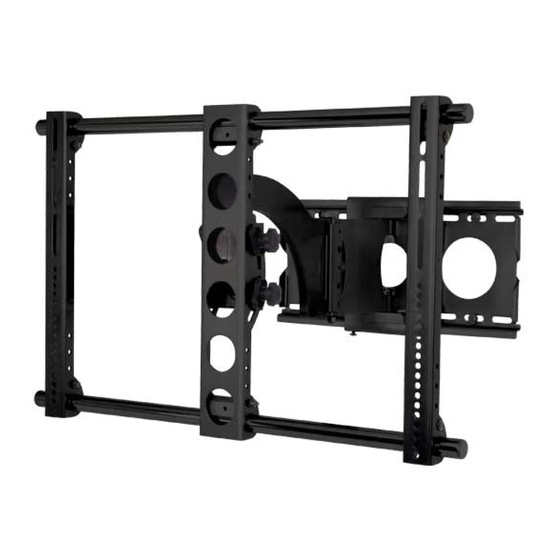
- Page 3 Assembly Instructions for Model: VMAA18 Thank you for choosing a Sanus Systems VisionMount™ wall mount. This model will hold 30 - 50 inch Plasma and LCD TVs weighing up to 130 lbs to a vertical wall. It is a full motion mount that will tilt, swivel, extend and can roll ±6° to level the TV.
- Page 4 Hardware: Hardware shown is actual size (10) Wire Tie -h * (7) Wire Tie Clip - g (4) Lag Bolt - i (4) Lag Bolt Washer - j (1) Allen Key - k (4) 2” Carriage Bolt - l (4) 1/4-20 Nut - m (2) Safety Bolt - n (2) Preventor Bolt - o Supplied Television Mounting Hardware: Hardware shown is actual size...
- Page 5 Step 1: Mounting Monitor Brackets to a television with a Flat Back First, determine the diameter of the Bolt (p,q,r,s) your TV requires by hand threading them into the threaded insert on the back of the TV. If you encounter any resistance stop immediately! Once you have determined the correct diameter, see the appropriate Diagram below. You will thread the Bolt through the appropriate Lock Washer (x,y,z,aa), a Washer (dd,ee), the Monitor Bracket (e) and finally into the TV.
- Page 6 Step 2: Mounting the Monitor Brackets to a television with a curved back or any other obstruction. First, determine the diameter of the Bolt (t,u,v,w) your TV requires by hand threading them into the threaded insert on the back of the TV. If you encounter any resistance stop immediately! Once you have determined the correct diameter, see the appropriate Diagram below.
- Page 7 Step 3: Add the Vise Assemblies to the Monitor Brackets: Note: Do not overtighten the 1/4-20 Nut (m). The Vise Assembly (f) should be able to rotate freely around the Car- riage Bolt (l). Place the Vise Assembly (f) between the two sides of the Monitor Bracket (e) so that the two jaws point toward the set of 1” diameter holes and the allen bolt is facing away from the television.
- Page 8 Step 4b: Attach the Arm Assembly (Part II) Position the Arm Assembly (b) so that the hook shaped tab shown in the Detailed View of Diagram 4b is on the top. Line up the two 1” diameter holes in the Monitor Bracket (e) at the other end of the Arm Assembly with the with the 1” Diameter Tubes (d). Continue to push the 1”...
- Page 9 Step 6: Hang the assembly onto the Wall Plate Warning: This step may require 2 people to lift the assembly onto the Wall Plate! Sanus is not responsible for injury or damage. Orient the Arm Assembly (b) so that the arm extends directly away from the television and the transfer plate is parallel with the televi- sion.
- Page 10 9. Wire Ties (h) can then be added to both the Wire Tie Clips, or the holes in the sides of either of the Monitor Brackets (e) Detailed View Diagram 9 Sanus Systems 2221 Hwy 36 West. St. Paul, MN 55113 11.15.05 Customer Service: 800.359.5520. See complementary Sanus products at www.sanus.com VMAA18ins_010606_ML.indd 10...
- Page 11 Nunca use piezas defectuosas. La instalación incorrecta puede provocar daños o lesiones graves. No utilice este producto para otro fin que no sea el explícitamente especificado por Sanus Systems. Sanus Systems no será responsable por daños ni lesiones debidos al montaje, ensamblaje o uso incorrectos. Llame a Sanus Systems antes de devolver los productos al punto de compra.
- Page 12 Tornillería: Toda la tornillería se muestra a tamaño real (10) Amarre del cable -h * (7) Mordaza para sujetar cables - g (4) Tirafondo - i (4) Arandela de tirafondo - j (1) Llave allen - k (4) Perno de carrocería de 5,1 cm - l (4) Tuerca 1/4-20 - m (2) Perno de seguridad - n (2) Perno del mecanismo de prevención - o...
- Page 13 Paso 1: Instalación de los soportes del monitor para un televisor con la parte trasera plana Determine primero el diámetro del perno (p,q,r,s) que necesita el televisor. Para ello deberá probar los pernos con la mano en el inserto roscado que se encuentra en la parte trasera del televisor. ¡Si encuentra alguna resistencia, deténgase inmediatamente! Una vez que haya determinado el diámetro correcto, vea el diagrama correspondiente más abajo.
- Page 14 Paso 2: Instalación de los soportes del monitor para un televisor con la parte trasera curva o con cualquier otra obstrucción Determine primero el diámetro del perno (t,u,v,w) que necesita el televisor. Para ello deberá probar los pernos con la mano en el inserto roscado que se encuentra en la parte trasera del mismo.
- Page 15 Paso 3: Adición de la placa de sujeción a los soportes del monitor Nota: No apriete demasiado la tuerca 1/4-20 (m). La placa de sujeción (f) debe poder girar libremente alrededor del perno de carrocería (l). Coloque la placa de sujeción (f) entre los dos lados del soporte del monitor (e) de manera que las dos mordazas queden orientadas hacia el conjunto de agujeros de 2,5 cm de diámetro y el perno allen quede orientado en sentido opuesto al televisor.
- Page 16 Paso 4b: Conexión del brazo (segunda parte) Coloque el brazo (b) de manera que la pestaña en forma de gancho que se muestra en la vista detallada del diagrama 4b quede en la parte superior. Alinee los dos agujeros de 2,5 cm de diámetro que se encuentran en el soporte del monitor (e), en el otro extremo del brazo, con los tubos de 2,5 cm de diámetro (d).
- Page 17 Paso 6: Colgado del conjunto en la placa para pared Advertencia: ¡En este paso podrían necesitarse 2 personas para levantar el conjunto hasta la placa para pared! Sanus no será responsable por lesiones o daños. Oriente el brazo (b) de manera que se extienda directamente desde el televisor y la placa de transferencia quede paralela a este último. ¡Podrían necesitarse dos personas para levantar algunos televisores! Levante el conjunto y enganche la placa de transferencia en la pestaña que se encuentra en la parte superior de la placa para pared (a), tal como se ilustra en el diagrama 6a.
- Page 18 (h) a ambas mordazas de sujeción del cable, o a los agujeros laterales de cualquiera de los soportes del monitor (e). Vista detallada Diagrama 9 Sanus Systems 2221 Hwy 36 West. St. Paul, MN 55113 USA 15.11.05 Servicio de atención al cliente: (800) 359-5520. Vea los productos complementarios de Sanus en el sitio www.sanus.com VMAA18ins_010606_ML.indd 18...
- Page 19 Verwenden Sie niemals beschädigte Teile! Unsachgemäße Montage kann Schäden am Gerät und schwere Verletzungen hervorrufen. Verwenden Sie das Produkt nicht für andere als von Sanus Systems explizit genannte Zwecke. Sanus Systems haftet nicht für Schäden oder Verletzungen, die durch unsachgemäße Montage, fehlerhaften Zusammenbau oder unsachgemäße Nutzung entstehen. Bitte rufen Sie Sanus Systems an, bevor Sie Produkte beim Händler reklamieren.
- Page 20 Zubehör: Zubehör ist maßstäblich dargestellt. (10) Kabelbinder – h * (7) Kabelbinderführung – g (4) Holzschraube – i (4) Unterlegscheibe für Holzschraube – j (1) Inbusschlüssel – k (4) Schlossschraube 2 Zoll – l (4) Mutter 1/4-20 – m (2) Sicherungsschraube – n (2) Sperrschraube –...
- Page 21 Schritt 1: Montage der Monitorhalterungen an einem Fernseher mit flacher Rückseite Zunächst die erforderliche Schraubengröße (p, q, r, s) für den Fernseher durch probeweises Eindrehen der Schrauben in die Gewindeeinsätze an der Rückseite des Fernsehers bestimmen. Wenn ein Widerstand zu spüren ist, sofort aufhören! Sobald der korrekte Durchmesser ermittelt ist, die entsprechende Abbildung unten beachten.
- Page 22 Schritt 2: Montage der Monitorhalterungen an einem Fernseher mit gekrümmter Rückseite oder anderen Hindernissen Zunächst die erforderliche Schraubengröße (t, u, v, w) für den Fernseher durch probeweises Eindrehen der Schrauben in die Gewindeeinsätze an der Rückseite des Fernsehers bestimmen. Wenn ein Widerstand zu spüren ist, sofort aufhören! Sobald der korrekte Durchmesser ermittelt ist, die entsprechende Abbildung unten beachten.
- Page 23 Schritt 3: Anbringen der Spannvorrichtungen an den Monitorhalterungen Hinweis: Die Mutter 1/4-20 (m) nicht überdrehen. Die Spannvorrichtung (f) muss sich frei um die Schlossschraube (l) drehen können. Die Spannvorrichtung (f) zwischen die beiden Seiten der Monitorhalterung (e) setzen, so dass die beiden Spannbacken auf die Bohrungen mit 2,5 cm Durchmesser zeigen und die Inbusschraube vom Fernseher weg zeigt.
- Page 24 Abbildung 4b hakenförmige Zunge Hinweis: Sanus Systems empfiehlt eine Zentrierung des Schwenkarms zwischen den Monitorhalterungen. Schritt 5: Montage der Wandplatte: Nur für Trägerbalken. Vorsicht: DIE HOLZSCHRAUBEN NICHT ÜBERDREHEN! Die Holzschrauben (i) nur so weit festziehen, dass die Holzschraubenunterlegscheibe (j) fest gegen die Wandplatte (a) drückt.
- Page 25 Vorsicht: Möglicherweise sind zwei Personen erforderlich, um die komplette Baugruppe auf die Wandplatte zu heben! Sanus Systems haftet nicht für Personen- oder Sachschäden. Den Schwenkarm (b) so drehen, dass er direkt vom Fernseher weg zeigt und die Transferplatte parallel zum Fernseher steht. Bei manchen Fernsehern sind zwei Personen zum Anheben erforderlich! Die komplette Baugruppe anheben und die Transferplatte auf der Nase an der Oberseite der Wandplatte (a) wie in Abbildung 6a einhaken.
- Page 26 Bohrungen an den Seiten der Monitorhalterungen (e) Kabelbinder (h) angebracht werden. Detailansicht Abbildung 9 Sanus Systems 2221 Hwy 36 West. St. Paul, MN 55113, USA 15.11.05 Kundendienst: 800.359.5520. Siehe ergänzende Sanus-Produkte unter www.sanus.com. VMAA18ins_010606_ML.indd 26 1/13/06 3:05:09 PM...
- Page 27 Sanus Systems. Sanus Systems ne pourra être tenu responsable de dommages ou de blessures dus à un montage incorrect, à un assemblage incorrect ou à un usage incorrect. Veuillez contacter Sanus Systems avant de retourner les produits au point de vente.
- Page 28 Matériel : Le matériel est illustré grandeur réelle. (10) Serre-câble - h * (7) Attache de serre-câble - g (4) Tire-fond - i (4) Rondelle de tire-fond - j (1) Clé Allen - k (4) Boulon mécanique de 2 pouces - l (4) Écrou 1/4-20 - m (2) Boulon de sécurité...
- Page 29 Étape 1 : Montage des supports du moniteur sur un téléviseur à panneau arrière plat Déterminez d’abord le diamètre du boulon (p, q, r, s) adapté à votre téléviseur en les vissant à la main dans l’insert fileté du panneau arrière du téléviseur.
- Page 30 Étape 2 : Montage des supports du moniteur sur un téléviseur à panneau arrière courbé ou à tout autre panneau ayant des obstructions. Déterminez d’abord le diamètre du boulon (t, u, v, w) adapté à votre téléviseur en les vissant à la main dans l’insert fileté du panneau arrière du téléviseur.
- Page 31 Étape 3 : Ajout de l’étau sur les supports du moniteur : Remarque : Ne serrez pas trop l’écrou 1/4-20 (m). L’étau (f) doit pouvoir tourner librement autour du boulon mécanique (l). Placez l’étau (f) entre les deux côtés du support du moniteur (e) de sorte que les deux mâchoires pointent vers les trous de 2,5 cm et que la vis Allen pointe dans le sens opposé...
- Page 32 Étape 4b : Fixation du bras sur le téléviseur (partie II) Placez le bras (b) de sorte que la patte en forme de crochet illustrée sur la vue détaillée du schéma 4b se trouve en haut. Alignez les deux trous de 2,5 cm de diamètre dans le support du moniteur (e) à l’autre extrémité du bras avec les tubes de 1 pouce de diamètre (d). Continuez de pousser les tubes de 1 pouce de diamètre à...
- Page 33 Étape 6 : Suspension de l’assemblage sur la plaque murale Avertissement : Cette étape nécessite l’intervention de deux personnes pour soulever l’assemblage et le déposer sur la plaque murale ! Sanus n’assume aucune responsabilité quant aux blessures ou aux dommages. Orientez le bras (b) de sorte qu’il puisse se déployer en s’éloignant directement du téléviseur et que la plaque de transfert soit parallèle au téléviseur.
- Page 34 9. Ajoutez ensuite les serre-câbles (h) aux attaches de serre-câble ou aux trous sur les côtés des supports du moniteur (e). Vue détaillée Schéma 9 Sanus Systems 2221 Hwy 36 West. St. Paul, MN 55113 USA 11.15.05 Service à la clientèle : 800.359.5520. Pour les produits Sanus complémentaires, visitez le site www.sanus.com VMAA18ins_010606_ML.indd 34...
- Page 35 L’installazione errata può causare danni o lesioni gravi. Non utilizzare questo prodotto per scopi diversi da quelli specificamente indicati dalla Sanus Systems. La Sanus Systems non è responsabile di danni o lesioni causati da montaggio o utilizzo non corretti. Chiamare la Sanus Systems prima di riportare i prodotti al punto vendita.
- Page 36 Minuteria metallica: La minuteria metallica è mostrata nelle dimensioni reali (10) tirafili - h * (7) clip tirafili - g (4) tirafondo - i (4) rondella per tirafondo - j (1) chiave a brugola - k (4) bullone di trasporto da 2 pollici - l (4) Dado 1/4-20 - m (2) bullone di sicurezza - n (2) bullone bloccante - o...
- Page 37 Fase 1: montare le staffe del monitor al televisore con retro piatto Innanzitutto, stabilire il diametro dei bulloni (p, q, r, s) che devono essere avvitati a mano alla TV nell’inserto filettato sul retro della TV. Se si incontrano delle resistenze, bloccarsi immediatamente! Una volta determinato il diametro corretto, vedere la Figura appropriata di seguito. Il bullone viene avvitato attraverso la controrondella appropriata (x,y,z,aa), una rondella (dd,ee), la staffa del monitor (e) e infine nel televisore.
- Page 38 Fase 2: montare le staffe del monitor al televisore con retro curvo o qualsiasi altra ostruzione. Innanzitutto, stabilire il diametro dei bulloni (t,u,v,w) che devono essere avvitati a mano alla TV nell’inserto filettato sul retro della TV. Se si incontrano delle resistenze, bloccarsi immediatamente! Una volta determinato il diametro corretto, vedere la Figura appropriata di seguito. Il bullone viene avvitato attraverso la controrondella appropriata (x,y,z,aa), una rondella (dd,ee), la staffa del monitor (e), una seconda rondella (dd - solo diametri M4/M5), un distanziale (bb,cc) e infine nella TV.
- Page 39 Fase 3: aggiungere il gruppo morsa alle staffe del monitor: Nota: non serrare eccessivamente il dado da 1/4-20 (m). Il gruppo della morsa (f) deve poter ruotare liberamente attorno al bullone di trasporto (l). Inserire il gruppo della morsa (f) tra i due lati della staffa per monitor (e) in modo che le due ganasce puntino verso il set di fori di dia- metro di 1 pollice e il bullone esagonale sia rivolto lontano dal televisore.
- Page 40 Fase 4b: collegare il gruppo del braccio (Parte II) Posizionare il gruppo del braccio (b) in modo che la linguetta a forma di gancio mostrata nella Vista dettagliata della Figura 4b si trovi nella parte superiore. Allineare i due fori del diametro di 1 pollice nella staffa del monitor (e) all’altra estremità del gruppo del braccio con i tubi del diametro di 1 pollice (d).
- Page 41 Fase 6: appendere il gruppo sulla piastra per parete Avvertenza: questa fase può richiedere la presenza di 2 persone per sollevare il gruppo sulla piastra per parete! La Sanus non è responsabile di eventuali lesioni o danni. Orientare il gruppo del braccio (b) in modo che il braccio si estenda direttamente lontano dal televisore e che la piastra di trasferimento sia parallela con il televisore.
- Page 42 Vista dettagliata della Figura 9. I tirafili (h) possono quindi essere aggiunti alle clip dei tirafili o ai fori sui lati di ogni staffa per monitor (e). Vista dettagliata Figura 9 Sanus Systems 2221 Hwy 36 West. St. Paul, MN 55113 USA 11.15.05 Assistenza clienti: 800.359.5520. Vedere i prodotti complementari Sanus al sito www.sanus.com VMAA18ins_010606_ML.indd 42...
- Page 43 Инструкция по сборке крепления модели VMAA18 Благодарим Вас за приобретение настенного крепления Sanus Systems VisionMount™ . Эта модель предназначена для установки жидкокристаллических или плазменных телевизоров с диагональю от 30 до 50 дюймов и весом до 59 кг на вертикальные стены. Установка позволяет проводить ориентацию телевизора в вертикальной и в горизонтальной...
- Page 44 Крепежные детали: Изображены в реальном размере Скоба для крепления кабеля (g) – 7 шт. Обвязка для кабеля (h*) – 10 шт. Шуруп под ключ (i) – 4 шт. Шайба под шуруп под ключ (j) – 4 шт. Ключ шестигранный (k) – 1 шт. Болт...
- Page 45 Шаг 1. Прикрепление крепежных скоб к телевизору с плоской задней панелью Сначала нужно определить диаметр винта (p, q, r, s), который подходит для Вашего телевизора. Для этого попробуйте вручную ввинтить каждый винт в заднюю панель телевизора. Почувствовав сопротивление, немедленно прекратите ввинчивать винт! Определив нужный диаметр,рассмотрите...
- Page 46 Шаг 2. Прикрепление крепежных скоб к телевизору, задняя панель которого искривлена или имеет выступы. Сначала нужно определить диаметр винта (t,u,v,w), который подходит для Вашего телевизора. Для этого попробуйте вручную ввинтить каждый винт в заднюю панель телевизора. Почувствовав сопротивление, немедленно прекратите ввинчивать винт! Определив...
- Page 47 Шаг 3. Установка зажимных устройств на крепежные скобы для монитора Примечание: не затягивайте гайку 1/4-20 (m) слишком сильно. Зажимное устройство (f) должно свободно вращаться вокруг болта с квадратным подголовком (l). Установите зажимное устройство (f) в паз в крепежной скобе для монитора (e) таким образом, чтобы две губки были обращены...
- Page 48 Шаг 4b. Присоединение кронштейна к телевизору (Часть 2) Поверните кронштейн (b) крючкообразным выступом, обозначенным на рисунке 4b, кверху. Два отверстия диаметром 2,5 см в крепежной скобе для монитора (e) на противоположном конце кронштейна разместите на одной линии с трубками диаметром 2,5 см (d).Проведите трубки диаметром 2,5 см через скобу на кронштейне и через вторую крепежную скобу для монитора.
- Page 49 Шаг 6. Прикрепление телевизора к настенной крепежной пластине Внимание! Чтобы установить кронштейн на настенную крепежную пластину, может понадобиться два человека! Компания Sanus не несет ответственности за травмы и порчу имущества. Поверните кронштейн (b) перпендикулярно к плоскости телевизора, так, чтобы опорная пластина была параллельной к плоскости...
- Page 50 для кабелей или к отверстиям по бокам крепежных скоб для монитора (e). Увеличенное изображение Рисунок 9 Компания Sanus Systems 2221 Hwy 36 West. St. Paul, MN 55113 USA 15.11.05 Служба работы с покупателями: 800.359.5520. См. дополнительные изделия производства Sanus на веб-сайте www.sanus.com VMAA18ins_010606_ML.indd 50...
- Page 51 (1) 防止装置 - c* (4) バイス組立部品 - f * (2) 1 インチ径のパイプ - d (2) モニター取付金具 - e Sanus Systems 2221 Hwy 36 West. St. Paul, MN 55113 USA 11.15.05 カスタマーサービス :800.359.5520. その他の Sanus 製品については www.sanus.com をご覧ください VMAA18ins_010606_ML.indd 51 1/13/06 3:05:26 PM...
- Page 52 金具:金具は実サイズで表示されています (10) 配線結束ワイヤー - h * (7) 配線結束クリッ プ - g (4) ラグボルト- i (4) ラグボルトワッシャー - j (1) アレンキー - k (4) 2 インチのキャリッジボルト - l (4) 1/4-20 ナット - m (2) 安全ボルト - n (2) 防止装置ボルト - o 梱包されているテレビ取り付け金具:金具は実サイズで表示されています...
- Page 53 手順 1 :背面が平らなテレビにモニター取付金具を取り付ける まず、 テレビの背面にあるねじ込みインサートに各種ボルト (p、 q、 r、 s) を手で差し込んでみて、 ご使用のテレビに適したボルトの 直径を選定します。 電気抵抗を感じたら、 すぐに中断してください!適切な直径が決まったら、 以下の該当する図をご覧ください。 ボ ルトを適切なロックワッシャー (x、 y、 z、 aa)、 ワッシャー (dd、 ee) 、 モニター取付金具 (e) に通した後、 テレビに差し込みます。 モニ ター取付金具が中央の高さに位置し、 金具同士が平行になっていることを確認します。 この手順を繰り返して、 それぞれのモニター 取付金具を 2 本のボルトでテレビに固定します。 注意 : 背面に丸みのあるテレビやその他の凹凸があるテレビは、 手順 2 をご覧ください。 この手順が終了したら、 手順 3 に進みます。 M4 径ボルト...
- Page 54 手順 2:背面に丸みのあるテレビやその他の凹凸があるテレビにモニター取付金具を取り付ける。 まず、 テレビの背面にあるねじ込みインサートに各種ボルト (t、 u、 v、 w) を手で差し込んでみて、 ご使用のテレビに適したボルトの 直径を選定します。 電気抵抗を感じたら、 すぐに中断してください!適切な直径が決まったら、 以下の該当する図をご覧ください。 ボ ルトを適切なロックワッシャー (x、 y、 z、 aa)、 ワッシャー (dd、 ee) 、 モニター取付金具(e) 、 2 つめのワッシャー (dd - M4/M5 径 の場合のみ)、 スペーサー (bb、 cc) に通した後、 テレビに差し込みます。 モニター取付金具が中央の高さに位置し、 金具同士が平行 になっていることを確認します。...
- Page 55 手順 3:バイス組立部品をモニター取付金具に取り付ける : 注意: 1/4-20 ナット (m) を締めすぎないようにしてください。 バイス組立部品 (f) は、 キャリッジボルト (l) を軸に自由に 回るようにしておきます。 バイス組立部品 (f) をモニター取付金具 (e)の 2 つの面の間に置いて、 2 つのかみあい口が1インチ直径の穴の方に向き、 アレン ボルトがテレビとは反対の方向に向くようにします。 2 インチのキャリッジボルト (l) をモニター取付金具の側面の角穴に通し、 バイス組立部品の穴に通してから、 モニター取付金具の反対側の角穴に通します。 次に、 1/4-20 ナット (m) を 2インチキャリッ ジボルトの先端に締め付けます。 モニター取付金具の下部についても、 この手順を繰り返します。 最後に、 2 つめのモニター取付 金具についても、...
- Page 56 手順 4b:アーム組立部品の取り付け (パートII) 図 4b の詳細図に表示されているフック型のタブが上になるようにアーム組立部品 (b) を配置します。 アーム組立部品のもう一 方にあるモニター取付金具 (e) の 1 インチ径の 2 つの穴を、 1 インチ径のパイプ (d) に合わせます。 1 インチ径のパイプをアー ム組立部品の取付金具に通し、 もう一方のモニター取付金具を貫通するまで押し続けます。 この場合も同様に、 1 インチ径のパ イプがかみあいの間を通るように、 アーム組立部品と 2 つめのモニター取付金具の両方についているバイス組立部品 (f) の配 置を確認します。 1 インチ径のパイプが所定の位置に収まったら、 2 つのモニター取付金具の 4 つのバイス組立部品についてい るアレンボルトをアレンキー...
- Page 57 手順 6:組立部品を壁面プレートに取り付ける 警告: この手順では、 組立部品を壁面プレートに持ち上げるには 2 人で行う必要があります!Sanus では、 ケガや破損につい ての責任は負いかねます。 テレビからアームがまっすぐ伸び、 移動プレートがテレビと平行になるように、 アーム組立部品 (b) の方向を決めます。 テレビに よっては 2 人で持ち上げる必要があります!組立部品を持ち上げ、 図 6a のように、 移動プレートを壁面プレート (a) の上端の タブに引っ掛けます。 移動プレートを壁面プレート上で左右に動かし、 適切な位置になるまで、 水平方向に調整します。 図 6b の 詳細図 のように、 安全ボルトが壁面プレートの下部にあるタブの後ろ側に設置されるように、 安全ボルト (n) をそれぞれ移動 プレートの下部にある 2 つの穴の 1 つに差し込んで固定します。 図...
- Page 58 部、 防止装置 (c) の側面、 およびピローブロックの上部と下部にある穴に取り付けることができます。 その後、 配線結束ワイヤー (h) を両方の配線結束クリッ プ、 あるいは、 どちらかのモニター取付金具 (e) の側面にある穴に取り付けます。 詳細図 図 9 Sanus Systems 2221 Hwy 36 West. St. Paul, MN 55113 USA 11.15.05 カスタマーサービス :800.359.5520. その他の Sanus 製品については www.sanus.com をご覧ください VMAA18ins_010606_ML.indd 58 1/13/06 3:05:30 PM...
- Page 59 VMAA18 型号装配说明 感谢您选用 Sanus Systems VisionMount™ 墙架。本型号产品可将 30 - 50 英寸的等离子和液晶电视机安装至垂直的墙面上, 承重可达 59 kg。此显示器架具有全动功能,可以倾斜、旋转、伸展和滚转 ±6° 以调节电视机角度。 安全警告: 如果您不理解这些说明或对安装的安全性有任何疑问,请致电有资格的承包商或与 Sanus 联系,联系电话:800.359.5520(美国)或 请仔细检查以确保零件无缺少或缺陷。我们的客户服务代表会 31 (0) 20 5708938(欧洲)。您也可以访问我们的网站 www.sanus.com。 迅速为您的安装问题提供协助,以及解决零件缺少或缺陷的问题。通过授权经销商所购产品的替换零件将直接送货上门。切勿 使用有缺陷的零件。安装不正确可能会导致损坏或严重受伤。切勿将本品用于 Sanus Systems 未明示的任何其它目的。Sanus Systems 对由于安装不正确、装配不正确或使用不当引起的损坏或受伤不承担任何责任。退货至购买点前请先致电 Sanus Sys- tems。 必需的工具:3/16 英寸钻头、成套扳手和飞利浦螺丝刀 所提供的零件和五金件:部分零件未按相同比例显示* (1) 墙板 - a (1) 臂组件...
- Page 60 五金件:以实际尺寸显示五金件 ( 1 0 ) 扎 带 - h * (7) 扎线夹 - g (4) 方头螺栓 - i (4) 方头螺栓垫圈 - j 内 六 角 扳 手 ( 1 ) (4) 2 英寸车身螺栓 - l (4) 1/4-20 螺母 - m (2) 安全螺钉...
- Page 61 步骤 1:将显示器架安装到背面平直的电视机上 首先,用手将螺钉 (p,q,r,s) 旋入电视机背面的螺孔以确定电视机所需螺钉的直径。如果遇到任何阻力,请立即停止!确定正确的 直径后,请查看如下相应图示。螺钉将依次穿过相应的锁紧垫圈 (x,y,z,aa)、垫圈 (dd,ee) 和显示器架 (e),并最终旋入电视机中。 请确保两个显示器架垂直居中且相互齐平。重复这个步骤直到每个显示器架都使用两个螺钉固定在电视机上。 注意:对于曲背面或者背面不平的电视机,请参见步骤 2。完成该步骤后,继续步骤 3 M4 直径螺钉 M6 直径螺钉 图 1 M5 直径螺钉 M8 直径螺钉 VMAA18ins_010606_ML.indd 61 1/13/06 3:05:32 PM...
- Page 62 步骤 2:将显示器架安装到曲背面或者任何其它背面不平的电视机上。 首先,用手将螺钉 (t,u,v,w) 旋入电视机背面的螺孔以确定电视机所需螺钉的直径。如果遇到任何阻力,请立即停止!确定正确 的直径后,请查看如下相应图示。螺钉将分别穿过相应的锁紧垫圈 (x,y,z,aa)、垫圈 (dd,ee)、显示器架 (e)、第二片垫圈(dd - 仅 M4/M5 直径)和间隔块 (bb,cc),并最终旋入电视机中。请确保两个显示器架垂直居中且相互齐平。重复这个步骤直到每个显示 器架都使用两个螺钉固定在电视机上。 M4 直径螺钉 M6 直径螺钉 图 2 M5 直径螺钉 M8 直径螺钉 VMAA18ins_010606_ML.indd 62 1/13/06 3:05:33 PM...
- Page 63 步骤 3:将虎钳组件安装到显示器架上: 注意:切勿将 1/4-20 螺母 (m) 旋得过紧。虎钳组件 (f) 应能绕着车身螺栓 (l) 自由旋转。 将虎钳组件 (f) 放置在显示器架 (e) 两侧边的中间,使虎钳的两个钳口分别对准 2.5 cm 直径孔并且使艾伦螺钉朝着背离电视 机的方向。然后将 2 英寸车身螺栓 (l) 依次穿过显示器架侧边上的方孔、虎钳组件上的孔和显示器架另一侧边上的方孔。最 后,将 1/4-20 螺母 (m) 从 2 英寸车身螺栓的末端旋入。重复此步骤在显示器架的底部进行安装。最后在第二个显示器架上 重复以上步骤。参阅图 3 以获得帮助。 详细视图 图 3 钳口 步骤 4a:将臂组件安装到电视机上(第 I 部分) 警告:2.5 cm 直径管...
- Page 64 步骤 4b:安装臂组件(第 II 部分) 调整臂组件 (b) 使臂组件上的钩状突起朝上(如图 4b 的详细视图所示)。调整位于臂组件另一端的显示器架 (e) 上的两个 2.5 cm 直径孔,使其与 2.5 cm 直径管 (d) 处于同一条直线上。继续将 2.5 cm 直径管穿过臂组件上的支架,然后再穿过另 一个显示器架。再次确保臂组件和第二个显示器架上的虎钳组件 (f) 的方向,以便 2.5 cm 直径管可从虎钳组件的钳口之间穿 过。2.5 cm 直径管到位后,即用内六角扳手 (k) 旋紧位于两个显示器架上的四个虎钳组件的艾伦螺钉,从而将电视机牢牢地 固定到显示器架上。接下来,将臂组件滑动到两个显示器架之间所需的位置上,旋紧位于臂组件上的虎钳组件的另外两个艾 伦螺钉。 详细视图 图 4b 突起 请注意: Sanus 建议使臂组件位于两个显示器架的中间位置。 步骤...
- Page 65 步骤 6:将装配体挂到墙板上 警告:此步骤可能需要两个人才能抬起装配体并将其安装到墙板上!Sanus 对由此造成的受伤或损坏不承担任何责任。 调整臂组件 (b),使支臂伸展并远离电视机,并且使传递板与电视机平行。有些电视机需要两个人才能将其抬起!抬起装配 体使传递板钩住墙板 (a) 顶部的突起(如图 6a 所示)。在墙板上水平地左右调整传递板至所需位置。将每个安全螺钉 (n) 分 别旋入传递板底部的两个孔中并将其旋紧,这样如图 6b 所示每个安全螺钉都位于墙板底部的突起之后。 图 6a 图 6b 详细视图 墙 底部突起 传递板 步骤 7:将显示器放置水平并调整张力 警告:请勿取下图 7 中标记的受拉螺母! 电视机安装到墙板 (a) 上并旋紧安全螺钉 (n) 后,可将电视机调整至水平位置。稍微松动臂组件 (b) 背面的两个艾伦螺钉。这两 个螺钉松动后,可在 ±6 范围内调整电视机位置直至水平。电视机水平后,重新旋紧两个艾伦螺钉。调整旋钮的紧度,然后 ° 倾斜电视机,就可调整电视机的倾斜度。稍微旋松或旋紧图...
- Page 66 力。理线扎带可装在多个位置以使线缆不被卷夹。如图 9 的详细视图所示,只需将扎带夹 (g) 向下按到位,便可将其安装在调 整臂组合 (b) 的上下两端、防护片 (c) 的侧面,以及带座外球面轴承的上下两端。然后便可将扎带 (h) 安放在扎带夹中,或者 任一个显示器架 (e) 的侧孔中。 详细视图 图 9 Sanus Systems 2221 Hwy 36 West, Saint Paul, MN 55113, USA 11.15.05 客户服务:800.359.5520. 有关 Sanus 公司的其它产品,请登录公司网站 www.sanus.com VMAA18ins_010606_ML.indd 66 1/13/06 3:05:35 PM...
Need help?
Do you have a question about the VisionMount VMAA18 and is the answer not in the manual?
Questions and answers