Sign In
Upload
Manuals
Brands
Eaton Manuals
Circuit breakers
150VCP-W 63
Eaton 150VCP-W 63 Manuals
Manuals and User Guides for Eaton 150VCP-W 63. We have
2
Eaton 150VCP-W 63 manuals available for free PDF download: Instructions For Installation, Operation And Maintenance, Instructions For Installation/Operation/Maintenance/Servicing
Eaton 150VCP-W 63 Instructions For Installation/Operation/Maintenance/Servicing (72 pages)
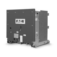
vacuum circuit breakers
Brand:
Eaton
| Category:
Circuit breakers
| Size: 7.04 MB
Table of Contents
Table of Contents
3
1 Introduction
6
Preliminary Comments and Safety Pre-Cautions
6
Warranty and Liability Information
6
Safety Precautions
6
General Information
6
Type VCP-W Vacuum Circuit Breaker Element Ratings (Tables 1, 2, 3, 4, 5, and 6)
7
Table 1. (ANSI Standards a ) Type VCP-W Vacuum Circuit Breaker through 15 Kv Rated Symmetrical Current Basis
7
Table 2. (ANSI Standards a ) Type VCP-W Vacuum Circuit Breaker 27 Kv Rated Symmetrical Current Basis
8
Table 3. (ANSI Standards) Type VCP-WC Extra Capability Vacuum Circuit Breaker 5-27 Kv Rated Symmetrical Current Basis
9
Rated Symmetrical Current Basis (Standard Ratings)
10
Outlines and Dimensions
11
Figure 1. Type VCP-W, VCPW-SE, and VCP-WC Circuit Breaker Outlines & DIM. in Inches (MM)
11
Figure 2. Type VCPW-ND Circuit Breaker Outlines and Dimensions in Inches (MM)
12
2 Safe Practices
13
Recommendations
13
3 Receiving, Handling, and Storage
13
General
13
Receiving
13
Handling
13
Storage
13
Tools and Accessories
14
Table 7. Accessories for 36-Inch Wide Breaker Compartments for 29-Inch Frame Breaker
15
Table 8. Narrow Design Accessories for 26-Inch-Wide Breaker Compartments
16
Table 9. 27 Kv VCP-W Accessories
17
Table 10. Simple Manual Ground and Test Devices-Bus Bar Type
18
Table 11. 15 Kv VCP-W Simple Manual Ground and Test Device-"Bail" and "Ball" Type a
18
Table 12. Complex Manual (Selectable) Ground and Test Device
18
Table 13. Simple Electrically Operated Ground and Test Device
19
Table 14. Simple Electrically Operated Ground and Test Device for VCP-W Without Key Interlocks
20
Table 15. Simple Electrically Operated Ground and Test Device for VCP-WXC
20
Table 16. 27 Kv Manual Ground and Test Device
20
Type VCP-W Vacuum Circuit Breaker Element Weights (Tables 18, 19, and 20)
21
Table 17. Dummy Elements a
21
Table 18. VCP-W ANSI Rated Breaker Weights a
21
Table 19. VCP-W IEC Rated Breaker Weights a
22
Table 20. VCP-W (K = 1) Breaker Weights a
22
Figure 3. Typical VCP-W Tools and Accessories
23
Operation, and Maintenance of Type Effective March
23
Figure 4. Typical Front View VCP-W Vacuum Circuit Breaker
24
Figure 5. Typical VCP-W Vacuum Circuit Breaker Element with Front Cover Removed
25
Figure 6. Typical Rear View VCP-W Vacuum Circuit Breaker Element
26
Figure 7. Typical VCP-W Vacuum Circuit Breaker Front Cover Arrangement
27
4 Initial Inspection and Installation
28
Introduction
28
Manual Operation Check
28
Vacuum Interrupter Integrity
28
Insulation
28
Contact Erosion and Wipe
28
Primary Circuit Resistance
28
Nameplate
28
Electrical Operation Check
28
Circuit Breaker Insertion and Removal
28
Figure 9. Insertion of the Drawout Extension Rails
29
Figure 10. Lifting and Setting the Breaker in the Housing
29
Figure 11. Front Panel
30
Figure 12. BPI Pan Assembly
31
Figure 13. Non-BPI Pan Assembly
32
Circuit Breaker Performance Check
33
Circuit Breaker/Structure Interfacing
34
Interface Interlocks/Interfacing Check
34
Figure 14. Engaging Extension Rails in a Lower Circuit Breaker Compartment
34
Figure 15. Typical VCP-W Circuit Breaker Bottom View
34
Figure 16. Pulling Secondary Disconnect Cage to Engage Secondaries in TEST Position
35
Figure 17. Engaging Levering-In Crank
35
5 Description and Operation
36
Introduction
36
Interrupter Assembly
36
Figure 18. Typical VCP-W Rear View Showing Vacuum Interrupters and Current Carrying System
36
Contact Erosion Indication
37
Contact Wipe and Stroke
37
Figure 19. Graphic Representation of Arc Interruption
37
Loading Spring Indicator
37
Phase Barriers
37
Vacuum Interrupter
37
Stored Energy Mechanism
38
Operation of Stored Energy Mechanism
38
Table 21. VCP-W & VCP-WC Circuit Breaker Barrier Configurations
38
Figure 20. Closing Cam and Trip Linkage
39
Figure 21. Charging Schematic
40
Charging
41
Closing Operation
41
Tripping Operation
41
Trip Free Operation
41
Control Schemes
41
Figure 22. Typical VCP-W DC and AC Control Schemes
42
Figure 23. 15 Kv VCP-WXC 63 Ka 1200-3000 a Special Power Plant Breakers
43
Figure 23. 5 Kv VCP-WXC 63 Ka 1200-3000 a Special Power Plant Breakers
44
Secondary Disconnects
45
Shunt Trip Device
45
Table 22. Circuit Breaker Timing
45
Timing
45
Under-Voltage Trip Device
45
Figure 24. 15 Kv Under-Voltage Trip Device Configuration
46
Interlocks and Interfacing
47
Levering Mechanism
47
Operations Counter
47
Ground Contact
47
MOC and TOC Switch Operations
47
6 Inspection, Maintenance, and Troubleshooting
48
Introduction
48
Frequency of Inspection and Maintenance
48
Qualified Personnel
48
General Torque Guidelines
49
Figure 25. Lubrication Points
49
Figure 26. 50 VCP-W 63 - 63 Ka Pole Unit
49
Table 23. Torque Guidelines
49
Inspection and Maintenance Procedures
50
Vacuum Interrupter Integrity Test
51
Contact Erosion and Wipe
51
Table 24. Test Voltage (Insulation and Vacuum Integrity)
51
Figure 27 . Vacuum Interrupter Showing Contact Erosion Indicator with Breaker Open
52
Figure 28. Vacuum Interrupter Showing Contact Erosion Indicator with Breaker Closed
52
Figure 29. Wipe Indication Procedure
52
Insulation
53
Insulation Integrity Check
53
Primary Circuit Resistance Check
53
Mechanism Check
53
Closure™ Test
53
Megger and Power Factor Testing
53
Table 25. Typical Resistance Measurements
53
Figure 30. Starting Tape at the Bottom of the Cam
54
Figure 31. Wrapping Tape up Around the Cam
54
Figure 32. Attaching Tape Around to the Back of the Cam
54
Figure 33. Attaching Closure Test Tool at Hole "A
54
Figure 34. Attaching Closure Test Tool at "B
54
Figure 35. Manually Charging the Closing Springs
55
Figure 36. Manually Closing the Circuit Breaker with the Marker in Hole "C
55
Figure 37. Top View of the Cam and Marker Interface
55
Figure 38. Move Marker 15° to the Right
55
Figure 39. Move Marker 15° to the Left
55
Figure 40. Remove Marked Masking Tape from the Cam
56
Figure 41. Place the Tape on the Right Side Panel of the Breaker
56
Figure 42. Illustrative Testing Tape Sample
56
Figure 43. Front View of Closure Tool Showing Mounting/Testing Locations (6352C49H01)
56
Figure 44. Typical Circuit Breaker Front View with Closure Tool Attached
56
Mechanism Lubrication
57
Finger Clusters and Switchgear Stab Lubrication
57
Main Contacts to Switchgear Primary Engagement
57
How to Determine the Manufacturing Date
57
Table 26. Closure Tool Mounting/Testing Locations by Circuit Breaker Type
57
Troubleshooting Chart
58
End of Life Procedures
58
Failure Reporting
58
7 Renewal Parts
59
General
59
Ordering Instructions
59
Table 27 . Recommended Renewal Parts for ANSI Rated Breakers
59
Table 28. Recommended Renewal Parts for IEC Rated Breakers
65
Table 29. Recommended Renewal Parts for GB Rated Breakers
69
8 Optional Accessories
70
Optional Factory Installed Roll-On-Floor Wheel Kit
70
Optional Automatic/Manual Hybrid Secondary for BPI Pan Assembly
70
Figure 45. Roll-On-Floor Wheel Kit (Shown Installed on a Standard 5/15 Kv VCP-W Breaker)
70
Optional 3,000 a Ball Screw Drive for BPI Pan Assembly
71
Figure 46. Optional Automatic/Manual Secondary for BPI Pan Assembly
71
Advertisement
Eaton 150VCP-W 63 Instructions For Installation, Operation And Maintenance (81 pages)
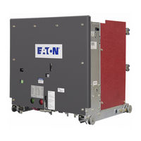
Vacuum Circuit Breakers
Brand:
Eaton
| Category:
Circuit breakers
| Size: 5.45 MB
Table of Contents
Table of Contents
3
Section 1: Introduction
7
Preliminary Comments and Safety Precautions
7
1-1.1 Warranty and Liability Information
7
1-1.2 Safety Precautions
7
General Information
7
Type VCP-W Vacuum Circuit Breaker Element Ratings (Tables 1.1, 1.2, 1.3, 1.4, 1.5, 1.6,1.7,1.8 & 1.9)
8
Outlines and Dimensions
14
Section 2: Safe Practices
16
Recommendations
16
Section 3: Receiving, Handling and Storage
17
General
17
Receiving
17
Handling
17
Storage
17
Tools and Accessories
18
Section 4: Initial Inspection and Installation
25
Introduction
25
Manual Operation Check
25
Vacuum Interrupter Integrity
25
Insulation
25
Contact Erosion and Wipe
25
Primary Circuit Resistance
25
Nameplate
25
Electrical Operation Check
26
4-8.1 Circuit Breaker Insertion and Removal
26
4-8.2 Operation Check Performance
32
Circuit Breaker/Structure Interfacing
33
4-9.1 Interface Interlocks/Interfacing Check
33
Section 5: Description and Operation
35
Introduction
35
Interrupter Assembly
35
5-2.1 Vacuum Interrupter
35
5-2.2 Contact Erosion Indication
36
5-2.4 Contact Wipe and Stroke
36
5-2.5 Phase Barrier
36
Stored Energy Mechanism
38
5-3.1 Operation of Stored Energy Mechanism
38
5-3.2 Charging
41
5-3.3 Closing Operation
41
5-3.4 Tripping Operation
41
5-3.5 Trip Free Operation
41
Control Schemes
41
5-4.1 Timing
45
5-4.2 Secondary Disconnects
45
5-4.3 Undervoltage Trip Device
45
Interlocks and Interfacing
47
Levering Mechanism
47
Operations Counter
47
Ground Contact
47
MOC and TOC Switch Operations
47
Section 6: Inspection, Maintenance and Troubleshooting
48
Introduction
48
Frequency of Inspection and Maintenance
48
6-2.1 Qualified Personnel
48
6-2.2 General Torque Guidelines
49
Inspection and Maintenance Procedures
50
Vacuum Interrupter Integrity Test
51
Contact Erosion and Wipe
52
Insulation
52
Insulation Integrity Check
53
Primary Circuit Resistance Check
54
Mechanism Check
54
6-9.1 Closure TM Test
54
Lubrication
58
Troubleshooting Chart
61
End of Life Procedure
61
Failure Reporting
61
Section 7: Renewal Parts
62
General
62
7-1.1 Ordering Instructions
62
Advertisement
Related Products
Eaton 150VCPW63(1500)
Eaton 150VCP-W 50
Eaton Cutler-Hammer 150 VCP-WR40C
Eaton Cutler-Hammer 150VCP-WRGC
Eaton 150VCP-W Series
Eaton 150VCP-W1500
Eaton 150 VCP-WXC 63
Eaton 150 VCP-WR 750
Eaton 150 VCP-WR 1500
Eaton 150VCP-W500
Eaton Categories
UPS
Circuit breakers
Industrial Equipment
Switch
Industrial Electrical
More Eaton Manuals
Login
Sign In
OR
Sign in with Facebook
Sign in with Google
Upload manual
Upload from disk
Upload from URL