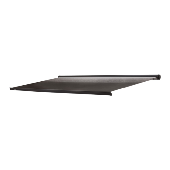
Dometic 9500E Installation Instructions Manual
(12 vdc) power case / cassette awning
Hide thumbs
Also See for 9500E:
- Operating instructions manual (15 pages) ,
- Installation instructions manual (11 pages) ,
- Operating instructions manual (12 pages)
Table of Contents
Advertisement
REVISION C
Form No. 3315066.000 12/16
(French 3315067.000_C)
©2016 Dometic Corporation
LaGrange, IN 46761
(12 VDC) POWER
CASE / CASSETTE AWNING
201(LL)(CC).003(#)
Read these instructions carefully. These
instructions MUST stay with this product.
USA
SERVICE OFFICE
Dometic Corporation
1120 North Main Street
Elkhart, IN 46514
RECORD THIS INFORMATION FOR FUTURE
REFERENCE:
Model Number
Serial Number
Date Purchased
Retailer / Qualified Installer
TYPE
9500E
MODEL
CANADA
Dometic Corporation
46 Zatonski, Unit 3
Brantford, ON N3T 5L8
CANADA
SERVICE CENTER &
DEALER LOCATIONS
Please Visit:
www.eDometic.com
Advertisement
Table of Contents

Summary of Contents for Dometic 9500E
- Page 1 REVISION C DEALER LOCATIONS SERVICE OFFICE Dometic Corporation Form No. 3315066.000 12/16 Dometic Corporation 46 Zatonski, Unit 3 Please Visit: (French 3315067.000_C) 1120 North Main Street Brantford, ON N3T 5L8 www.eDometic.com ©2016 Dometic Corporation Elkhart, IN 46514 CANADA LaGrange, IN 46761...
-
Page 2: Table Of Contents
This product can be installed by one person with brief help from additional personnel. Use these instructions to ensure correct installation and function of product. Dometic Corporation reserves the right to modify appearances and specifications without notice. TABLE OF CONTENTS INTRODUCTION ..................................2... -
Page 3: Important Safety Instructions
IMPORTANT SAFETY INSTRUCTIONS This manual has safety information and instructions to help I ncorrect [installation / operation / servicing / you eliminate or reduce the risk of accidents and injuries. maintaining] of this product can lead to seri- ous injury. Follow all instructions. Recognize Safety Information The installation MUST comply with all ap- ... -
Page 4: Specifications
SPECIFICATIONS Product Rating Door Clearance I f awning motor is operated for more than 3 Allow for sufficient clearance be- minutes, it will be disabled temporarily to pre- tween awning fabric and entry door to accommo- vent overheating. If this occurs, the motor will date awning pitch (slope). -
Page 5: Installation
SPECIFICATIONS 2. Mounting bolt hole pattern locations: Hole Pattern Locations IMPACT OR CRUSH HAZARD. 8′ 10′ 12′ 13′ 15′ 16′ Locate mounting bolts behind each shoulder 6 3/8″ assembly (lateral arm attachment) to provide 60 7/8″ proper support. Otherwise, awning may become unstable and could bend or collapse. -
Page 6: Install Mounting Bracket
INSTALLATION b. If sufficient structural support is NOT pres- 3. Maintain a minimum of 1/2″ clearance at top and ent, proceed to step (c). Otherwise, skip to sides of awning case. step (2). A dditional clearance is recommended to c. -
Page 7: Install Wiring And Electrical Kits
(cut power) to awning when ig- nition is ON. See instructions included with your Install Wiring And Electrical Kits Dometic Corporation ignition interlock kit for additional wiring instructions. ELECTRICAL SHOCK HAZARD. 3. Mark awning wiring hole location. See (FIG. 3). -
Page 8: Install Awning
INSTALLATION II. Subtract awning bracket length from aw- V erify connections will mate BLACK RV ning back rail length, and divide sum by wire to BLACK (or BLUE) awning mo- two. tor wire, and RED RV wire to RED (or BROWN) awning motor wire. -
Page 9: Verify Motor And Remote Functionality
INSTALLATION Verify Motor And Remote Functionality 6. IMPACT OR CRUSH HAZARD. Do NOT operate or leave awning unattended un- 1. PINCH HAZARD. Maintain a til it is securely fastened to mounting bracket(s). horizontal distance of at least 16″ between fully Otherwise, awning could dislodge and fall. -
Page 10: Verify Wind Sensor Functionality
INSTALLATION Verify Wind Sensor Functionality FIG. 16 S kip this section if awning is NOT equipped with a wind sensor (located on inside surface of lead rail). PINCH HAZARD. Maintain a hori- zontal distance of at least 16″ between fully open awning and any permanent object. -
Page 11: Adjust Lateral Arm Assemblies (If Required)
ADJUSTMENTS (OPTIONAL) Adjust Lateral Arm Assemblies (If 3. Support weight of lead rail and lateral arm as- semblies securely. Required) 4. IMPACT OR CRUSH HAZARD. Do NOT allow lateral arm assem- Make sure lateral arm assemblies are tied and blies to rub against lower lip of back rail when clos- supported securely (with lead rail) before loos- ing, or allow awning fabric to contact shoulder base... - Page 12 ADJUSTMENTS (OPTIONAL) 3. IMPACT OR CRUSH HAZARD. 5. Adjust lateral arm assembly’s closing height. See (FIG. 21), (FIG. 22), & (FIG. 23). Make sure lead rail and lateral arm assemblies are supported securely before loosening fasten- R epeat this step for each lateral arm as- ers.
-
Page 13: Adjust Lead Rail Alignment (If Required)
ADJUSTMENTS (OPTIONAL) Adjust Lead Rail Alignment (If Required) FIG. 24 After fabric slope and lateral arm assembly adjust- ments, the lead rail may need realignment with top Adjustment RH End and end caps. See (FIG. 24). Screw 1. C heck alignment of lead rail against top and end caps.


Need help?
Do you have a question about the 9500E and is the answer not in the manual?
Questions and answers