
Related Manuals for Zennio HeatingBOX 24V 4X


Summary of Contents for Zennio HeatingBOX 24V 4X
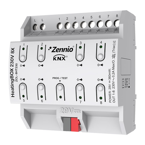
- Page 1 HeatingBOX 24V / 230V 4X / 8X 4-Output / 8-Output 24V / 230V Heating Actuator ZCL4HT24 ZCL8HT24 ZCL-4HT230 ZCL-8HT230 Application programme version: [1.2] User manual edition: [1.2]_a www.zennio.com...
-
Page 2: Table Of Contents
Cyclical Monitoring .................. 22 2.4.1.4 Startup ....................24 2.4.1.5 Characteristic Curve ................. 25 2.5 Manual Control ......................28 ANNEX I. Communication Objects of HeatingBOX 24V ............. 31 ANNEX II. Communication Objects of HeatingBOX 230V ............35 http://www.zennio.com Technical Support: http://support.zennio.com... -
Page 3: Document Updates
HeatingBOX DOCUMENT UPDATES Version Changes Page(s) New devices: HeatingBOX 24V 4X / 8X. Changes in the application programme: New module: Heartbeat. New parameters: o Value for open valve. o Opening minimum value. [1.2]_a Output lock due to short circuit/overload error. -
Page 4: Introduction
HeatingBOX 1 INTRODUCTION 1.1 HeatingBOX HeatingBOX from Zennio is a heating-specific KNX actuator equipped, with four or eight independent outputs for controlling 24V or 230V valves, depending on the device. The most outstanding features are: 4 or 8 configurable outputs for controlling electromechanical valves. -
Page 5: Installation
Note: if this button is held while plugging the device into the KNX bus, the device will enter into safe mode. In such case, the LED will blink in red every 0.5 seconds. Phase Inputs (1): slots for the connection of the voltage lines (phase). Both inputs are internally shorted. http://www.zennio.com Technical Support: http://support.zennio.com... -
Page 6: Start-Up And Power Loss
Datasheet, bundled with the original packaging of the device and also available at www.zennio.com. 1.3 START-UP AND POWER LOSS During the start-up of the device and depending on the configuration, some specific actions may be performed. -
Page 7: Configuration
“1” to notify that the device is still working (still alive). Figure 3. Heartbeat The default values of each parameter will be highlighted in blue in this document, as follows: [default/rest of options]. http://www.zennio.com Technical Support: http://support.zennio.com... - Page 8 “Heating Controls” tab is always enabled in the tab tree on the left. See section 2.4 for details. Manual Control [disabled/enabled]: enables or disables the “Manual Control” tab in the tree on the left. See section 2.5 for details. http://www.zennio.com Technical Support: http://support.zennio.com...
-
Page 9: Thermostats
HeatingBOX implements four or eight Zennio thermostats, depending on the device outputs number, which can be enabled and configured independently. Please refer to the specific “Zennio Thermostat” user manual (available in the HeatingBOX product section at the Zennio homepage, www.zennio.com) for detailed information about the functionality and the configuration of the related parameters. -
Page 10: Logic Functions
Please refer to the specific “Logic Functions” user manual (available in the HeatingBOX product section at the Zennio homepage, www.zennio.com) for detailed information about the functionality and the configuration of the related parameters. -
Page 11: Heating Controls
All valves closed: it may be significant for the climate system whether all valves are currently closed or not (e.g., to switch off the climate unit in case they are). This notification can be restricted for a specific set of valves (so http://www.zennio.com Technical Support: http://support.zennio.com... - Page 12 From the “Configuration” screen is possible to enable/disable all the common functions required. In addition, each output can be individually enabled. Startup Delay [0…255][s]: delay after the device initialisation. Short Circuit/Overload Error Notification [disabled/enabled]: when enabled, the following one-bit objects will be available: http://www.zennio.com Technical Support: http://support.zennio.com...
- Page 13 / Send 1]. Delay [0…30…1440][min] [0…24][h]. Note: this delay must be greater than the cycle time (either in case of making use of an external device or of the 1-byte control method). See section 2.4.1. http://www.zennio.com Technical Support: http://support.zennio.com...
- Page 14 Periodicity [1…7…30][day]: sets the maximum time an output can remain still. Duration [1…5…255][min]: sets for how much time the output should switch its position, in case it has been still for more than the above periodicity. http://www.zennio.com Technical Support: http://support.zennio.com...
-
Page 15: Heating Output N
Valve type: sets the type of the valve connected to the output, which may be normally open (in the absence of power, the valve remains open) or normally closed (in the absence of power, the valve remains closed). http://www.zennio.com Technical Support: http://support.zennio.com... - Page 16 Lock function, which provides a one-bit object to temporarily deactivate the control of the output (valve), being possible to leave it as is until it gets unlocked, or to switch it to a particular position. Alarms: see section 2.4.1.2. Cyclical monitoring: see section 2.4.1.3. http://www.zennio.com Technical Support: http://support.zennio.com...
- Page 17 PWM Period [5…3600][s] [1…15…1440][min]: sets the PWM cycle time, i.e., the base time for the PWM modulation. The device will perform opening and closing orders to the valve alternatively in order to satisfy the control value. http://www.zennio.com Technical Support: http://support.zennio.com...
- Page 18 See Table 1 for details. Count with this output to: Notify That All Valves Are Closed [disabled/enabled]: when checked, the current output will be taken into account to determine whether all valves are closed or not. http://www.zennio.com Technical Support: http://support.zennio.com...
- Page 19 / Close Valve / Open Valve]. One-byte control [No Change / Specific Control Value]. When selecting the latter, the parameter Control Value [0…100] lets introducing the desired percentage value. Alarms [disabled/enabled]: enables or disables the Alarm function. See section 2.4.1.2. http://www.zennio.com Technical Support: http://support.zennio.com...
-
Page 20: Alarms
Alarm has priority over Alarm 2. If a channel is in alarm 2 and alarm 1 is activated, the alarm 1 action will be executed until the alarm 1 is deactivated, resuming the alarm 2 status (but without executing the alarm 2 action again). http://www.zennio.com Technical Support: http://support.zennio.com... - Page 21 (default option), the cyclical monitoring function will remain disabled. Action: sets the state the output should acquire once a lock order is received. The options depend on the control method: 1 bit: [No Change / Close Valve / Open Valve]. http://www.zennio.com Technical Support: http://support.zennio.com...
-
Page 22: Cyclical Monitoring
The reaction in case of failure can consist in: Set the output status to a specific position. Doing nothing. http://www.zennio.com Technical Support: http://support.zennio.com... - Page 23 Notify Through Communication Object [disabled/enabled]: enables the “[HCx] Control Value - Error” binary object, which will send the value “1” in case the communication has been interrupted, and the value “0” once the error is over. http://www.zennio.com Technical Support: http://support.zennio.com...
-
Page 24: Startup
Action: sets the state the output should acquire at the start-up of the actuator. The options depend on the control method: 1 bit: [Last Control Value (Before Bus Failure) / Close Valve / Open Valve]. http://www.zennio.com Technical Support: http://support.zennio.com... -
Page 25: Characteristic Curve
This function allows the integrator to define a specific curve for the valve control. By default, all control values received are directly applied to the valve (through a PWM signal) as shown in Figure 12. Actual Regulation 100% 100% Control Value Figure 12. Default Control Curve. http://www.zennio.com Technical Support: http://support.zennio.com... - Page 26 For control values greater than that of the last point, the actual regulation value will be 100%. For example, in Figure 14 all control values over 80% imply a regulation value of 100%. Actual Regulation 100% Control Value Figure 14. Characteristic Curve – Values Out of Range. http://www.zennio.com Technical Support: http://support.zennio.com...
- Page 27 (control value 1 < control value 2 < control value 3). Otherwise, an error message will appear to indicate the valve behaviour may not be as expected. http://www.zennio.com Technical Support: http://support.zennio.com...
-
Page 28: Manual Control
Under the Test Off Mode, the outputs can be controlled through both their communication objects and the actual pushbuttons located on the top of the device. Also, during this manual control mode, the control commands received by the bus will continue to be analysed and executed. http://www.zennio.com Technical Support: http://support.zennio.com... - Page 29 Test On) enabled by default. ETS PARAMETERISATION After enabling “Manual Control” in the Configuration screen (see section 2.1), a new tab will be incorporated into the tab tree on the left. Figure 16. Manual Control. The only two parameters are: http://www.zennio.com Technical Support: http://support.zennio.com...
- Page 30 (through the aforementioned object) of values “0” and “1”, or the opposite. Initialization [Unlocked / Locked / Last Value (Before Bus Failure)]: sets how the manual control should remain after the device start-up (after an ETS download or a bus power failure). http://www.zennio.com Technical Support: http://support.zennio.com...
-
Page 31: Annex I. Communication Objects Of Heatingbox 24V
“Functional range” shows the values that, with independence of any other values permitted by the bus according to the object size, may be of any use or have a particular meaning because of the specifications or restrictions from both the KNX standard or the application program me itself. Note: objects corresponding to outputs 5-8 are not available in HeatingBOX 24V 4X. Number... - Page 32 181, 211, 241 than 0% 32, 62, 92, 122, 152, 0 = PI signal 0%; 1 = PI signal greater 1 Bit C T R - - DPT_Switch [Tx] PI State (Heat) 182, 212, 242 than 0% http://www.zennio.com Technical Support: http://support.zennio.com...
- Page 33 [HCx] Unfreeze Alarm Alarm 333, 345, 357, 369, 381, 393, 405, 417 Alarm = Alarm 2 = No Alarm + Unfreeze 1 Bit C - - W - DPT_Ack [HCx] Unfreeze Alarm (1) -> End Alarm http://www.zennio.com Technical Support: http://support.zennio.com...
- Page 34 399, 411, 423 1 Bit C T R - - DPT_Bool [HC] Short Circuit/Overload Lock 0 = Unlocked; 1 = Locked 1 Bit C T - - - DPT_Trigger [Heartbeat] Object to Send '1' Sending of '1' Periodically http://www.zennio.com Technical Support: http://support.zennio.com...
-
Page 35: Annex Ii. Communication Objects Of Heatingbox 230V
1 Byte C T R - - DPT_HVACMode [Tx] Special Mode Status 1-byte HVAC Mode 163, 193, 223 3=Economy 4=Building Protection 2 Bytes C - - W - DPT_Value_Temp -273.00° - 670760.00° [Tx] Setpoint Thermostat Setpoint Input http://www.zennio.com Technical Support: http://support.zennio.com... - Page 36 0% 243, 244, 245, 246, 247, 248, 249, 250, 1 Bit C - - W - DPT_Bool [LF] (1-Bit) Data Entry x Binary Data Entry (0/1) 251, 252, 253, 254, 255, 256, 257, 258, http://www.zennio.com Technical Support: http://support.zennio.com...
- Page 37 [HCx] Unfreeze Alarm Unfreeze (1) -> End Alarm 334, 346, 358, 370, 1 Bit C T R - - DPT_Bool [HCx] Control Value - Error 0 = No Error; 1 = Error 382, 394, 406, 418 http://www.zennio.com Technical Support: http://support.zennio.com...
- Page 38 428, 429, 430, 431 1 Bit C T R - - DPT_Bool [HC] Short Circuit/Overload Lock 0 = Unlocked; 1 = Locked 1 Bit C T - - - DPT_Trigger [Heartbeat] Object to Send '1' Sending of '1' Periodically http://www.zennio.com Technical Support: http://support.zennio.com...
- Page 39 Join and send us your inquiries about Zennio devices: http://support.zennio.com Zennio Avance y Tecnología S.L. C/ Río Jarama, 132. Nave P-8.11 45007 Toledo (Spain). Tel. +34 925 232 002 www.zennio.com info@zennio.com...
Need help?
Do you have a question about the HeatingBOX 24V 4X and is the answer not in the manual?
Questions and answers