Table of Contents
Advertisement
Quick Links
IM-P117-39
1170152/1
CMGT Issue 1
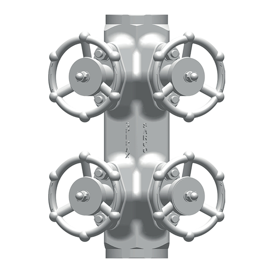
MSC-125 and MSC-160 Manifolds for Steam
Distribution and Condensate Collection
Installation and Maintenance Instructions
1. Safety information
2. General product
information
3. Installation
4. Commissioning
5. Operation
6. Maintenance
7. Spare parts
MSC04 shown
© Copyright 2017
IM-P117-39 CMGT Issue 1
1
Printed in GB
Advertisement
Table of Contents

Related Manuals for Spirax Sarco MSC-125


Summary of Contents for Spirax Sarco MSC-125
- Page 1 IM-P117-39 1170152/1 CMGT Issue 1 MSC-125 and MSC-160 Manifolds for Steam Distribution and Condensate Collection Installation and Maintenance Instructions 1. Safety information 2. General product information 3. Installation 4. Commissioning 5. Operation 6. Maintenance 7. Spare parts MSC04 shown © Copyright 2017...
-
Page 2: Safety Information
Determine the correct installation situation and direction of fluid flow. iv) Spirax Sarco products are not intended to withstand external stresses that may be induced by any system to which they are fitted. It is the responsibility of the installer to consider these stresses and take adequate precautions to minimise them. -
Page 3: Pressure Systems
1.9 Tools and consumables Before starting work ensure that you have suitable tools and/or consumables available. Use only genuine Spirax Sarco replacement parts. 1.10 Protective clothing Consider whether you and / or others in the vicinity require any protective clothing to protect against the hazards of, for example, chemicals, high / low temperature, radiation, noise, falling objects, and dangers to eyes and face. -
Page 4: Residual Hazards
1.16 Returning products Customers and stockists are reminded that under EC Health, Safety and Environment Law, when returning products to Spirax Sarco they must provide information on any hazards and the precautions to be taken due to contamination residues or mechanical damage which may present a health, safety or environmental risk. -
Page 5: General Product Information
2. General product information 2.1 General description A range of forged carbon steel compact manifolds with integral piston type stop valves for steam distribution and condensate collection duty. MSC manifolds can be used for either steam distribution duty or condensate collection duty depending on the way they are installed. - Page 6 2.2 Available types, sizes and pipe connections MSC manifolds are available with 4, 8 or 12 connections, with and without integral piston isolation valves designated: MSC04-125, MSC08-125 and MSC12-125 with 125mm pitch respectively DN15 and DN20 screwed BSP, NPT or socket weld to B16.11 Class 3000 tracer ports are available as standard.
-
Page 7: Pressure / Temperature Limits
SW, NPT Minimum operating temperature 0 °C 32 °F Note: For lower operating temperatures consult Spirax Sarco Designed for a maximum cold hydraulic test pressure of: 76 bar g 1 102 psi g 2.4 K v values All sizes Kv 1.8... -
Page 8: Installation
Any welding that is not being carried out by Spirax Sarco or their sub-vendors, will remain the full responsibility of the customer, user or their own appointed contractors / sub-vendors. -
Page 9: Operation
Fig. 2 Installation view from above MSC manifold Spacer M12 Nut M12 stud 50 mm Structural steelwork 4. Commissioning After installation or maintenance ensure that the system is fully functioning. Carry out tests on any alarms or protective devices. 5. Operation The integral piston valves should be either fully open or fully closed. -
Page 10: Maintenance
6. Maintenance Note: Before actioning any maintenance programme observe the 'Safety information' in Section 1. Warning The graphite stem sealing rings (items 8 and 9) contain thin stainless steel support rings which may cause physical injury if not handled and disposed of carefully. 6.1 Maintenance in service After the manifold is first put into service or after a change of sealing rings (8 and 9), the bonnet nuts (4) should be lightly followed up with the valve in the closed position. - Page 11 3 + 4 + 5 Fig. 3 View showing valve internals Washer Washer Top nut Domed lock-nut Fig. 4 View showing valve internals extractor tool Extractor tool Manifold inlet IM-P117-39 CMGT Issue 1...
- Page 12 6.4 Repacking the valve: With the valve dismantled, insert the valve internals extractor tool through the upper and lower sealing rings (8 and 9) and lantern bush (7) (See Figure 7). Firmly tap to ensure that the tool bottoms out in the bore and with a quarter turn of the handle carefully remove the two sealing rings (8 and 9) and the lantern bush (7).
- Page 13 3 + 4 + 5 Fig. 5 View showing valve internals Washer Washer Top nut Domed lock-nut Fig. 6 View showing valve internals extractor tool Extractor tool Manifold inlet IM-P117-39 CMGT Issue 1...
-
Page 14: Spare Parts
7. Spare parts The spare parts available are detailed below. To avoid any internal damage, the correct extractor tool must be used for removing the sealing rings - Please order seperately. Available spares Sealing ring set 8 and 9 Piston valve assembly 2, 4, 5, 6, 7, 8, 9, 10, 11 and 12 6, 7, 8 and 9 Piston valve sub-assembly... - Page 15 IM-P117-39 CMGT Issue 1...
- Page 16 IM-P117-39 CMGT Issue 1...
Need help?
Do you have a question about the MSC-125 and is the answer not in the manual?
Questions and answers