Advertisement
Quick Links
1570950 / 4
IM-P157-38
CMGT Issue 4
Steam/Water Mixing Stations
(MkII valves - 2002 onwards)
Safety and Operation
Installation and Maintenance Instructions
1. General safety information
2. General product information
3. How to size
4. Installation
5. Maintenance
6. Spare parts
7.
Fault finding
These instructions should be read by the Company Safety Officer
Steam/Water Mixing Stations (MkII valves - 2002 onwards) Safety and Operation
© Copyright 2020
1
IM-P157-38 CMGT Issue 4
Printed in GB
Advertisement

Related Manuals for Spirax Sarco MkII


Summary of Contents for Spirax Sarco MkII
- Page 1 4. Installation 5. Maintenance 6. Spare parts Fault finding These instructions should be read by the Company Safety Officer Steam/Water Mixing Stations (MkII valves - 2002 onwards) Safety and Operation © Copyright 2020 IM-P157-38 CMGT Issue 4 Printed in GB...
- Page 2 Steam/Water Mixing Stations (MkII valves - 2002 onwards) Safety and Operation IM-P157-38 CMGT Issue 4...
- Page 3 This is easily achieved by fitting Spirax Sarco depressurisation valves type DV (see separate literature for details). Discharge contents of the hose and station by pulling the gun trigger and eliminate pressure until water flow stops.
- Page 4 The mixing valve must always be operated with an element in the TCO1 to prevent steam reaching the hose. In the event that the hosedown station is used without an element in the TCO1 then Spirax Sarco will not accept any consequential liability for the operation of the hosedown station in this manner.
- Page 5 The mixing valve must always operate with an element in the TCO1 to prevent steam reaching the hose. In the event that the hosedown station is used without an element in the TCO1 then Spirax Sarco will not accept any consequential liability for the operation of the hosedown station in this manner.
- Page 6 Installation and Maintenance Instructions IM-P157-03. Design The Spirax Sarco steam/water mixing station is designed to provide hot water economically by blending steam and cold water quickly to the required user temperature. This temperature can be altered by turning the temperature adjustment knob. As the valve is not thermostatically controlled, in order to maintain a fixed hot water temperature the cold water pressure and flowrate must be constant.
- Page 7 Inter connecting pipe is not supplied with the mixing valve station. This pipe should be at least 0.5 m (19.3") long to prevent condensate backing up into the steam line. Fig. 1 ¾" and 1½" assembly shown Steam/Water Mixing Stations (MkII valves - 2002 onwards) Safety and Operation IM-P157-38 CMGT Issue 4...
- Page 8 50 - 100 3.50 - 7.0 3.57 - 7.14 12.0 54.4 5 - 50 0.35 - 3.5 0.36 - 3.57 12.0 54.4 Yellow Green Black Blue White Steam/Water Mixing Stations (MkII valves - 2002 onwards) Safety and Operation IM-P157-38 CMGT Issue 4...
- Page 9 (9.25 gal/min at 72.5 psi) With jet spray 25 l/min at 5 bar (5.50 gal/min at 72.5 psi) Capacities (approximate) Fig. 2 Supply pressure bar g Steam/Water Mixing Stations (MkII valves - 2002 onwards) Safety and Operation IM-P157-38 CMGT Issue 4...
- Page 10 50 °C is 32 l/min. 40 °C 50 °C 60 °C 70 °C 80 °C 90 °C 8 9 10 Supply pressure bar g Steam/Water Mixing Stations (MkII valves - 2002 onwards) Safety and Operation IM-P157-38 CMGT Issue 4...
- Page 11 70 °C 70 °C 80 °C 80 °C 90 °C 90 °C 8 9 10 9 10 Supply pressure bar g Supply pressure bar g Steam/Water Mixing Stations (MkII valves - 2002 onwards) Safety and Operation IM-P157-38 CMGT Issue 4...
- Page 12 130 N m (88 - 95 lbf ft) for ½" and ¾" valves. A torque setting of 180 to 200 N m (132 - 147 lbf ft) for 1" and 1½" valves. Remove the medium steam pressure range label and replace with the high pressure label. Steam/Water Mixing Stations (MkII valves - 2002 onwards) Safety and Operation IM-P157-38 CMGT Issue 4...
- Page 13 Cold water Steam inlet inlet Fig. 3 Steam/Water Mixing Stations (MkII valves - 2002 onwards) Safety and Operation IM-P157-38 CMGT Issue 4...
- Page 14 Steps 15 and 16. Note: The maximum hot water temperature is 90 °C (194 °F). 18. Close the gun. 19. Replace the bypass screw (9). Steam/Water Mixing Stations (MkII valves - 2002 onwards) Safety and Operation IM-P157-38 CMGT Issue 4...
- Page 15 Cold water Steam inlet inlet Fig. 3 Steam/Water Mixing Stations (MkII valves - 2002 onwards) Safety and Operation IM-P157-38 CMGT Issue 4...
- Page 16 The steam/water mixing valve station should be carefully unpacked and the contents checked against the packing list (see the Table on page 18 in conjunction with Figure 5). Steam/Water Mixing Stations (MkII valves - 2002 onwards) Safety and Operation IM-P157-38 CMGT Issue 4...
- Page 17 Inter connecting pipe is not supplied with the mixing valve station. This pipe should be at least 0.5 m (19.3") long to prevent condensate backing up into the steam line. Fig. 4 Steam/Water Mixing Stations (MkII valves - 2002 onwards) Safety and Operation IM-P157-38 CMGT Issue 4...
- Page 18 1" x ¾" Reducing 'T' ¾" x ½" 1" x ½" 1½" x ¾" Reducing bush ½" x " ¾" x " 1" x " Steam/Water Mixing Stations (MkII valves - 2002 onwards) Safety and Operation IM-P157-38 CMGT Issue 4...
- Page 19 Inter connecting pipe is not supplied with the mixing valve station. This pipe should be at least 0.5 m (19.3") long to prevent condensate backing up into the steam line. Fig. 5 Packing list Steam/Water Mixing Stations (MkII valves - 2002 onwards) Safety and Operation IM-P157-38 CMGT Issue 4...
- Page 20 Reducing nipple INLET TCO1 ½" and ¾" station only OUTLET 1" x ¾" reducing nipple 'T' piece Equal nipple Union Hose (with protective sleeve) Fig. 6 Steam/Water Mixing Stations (MkII valves - 2002 onwards) Safety and Operation IM-P157-38 CMGT Issue 4...
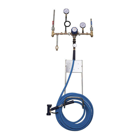
- Page 21 Fig. 7 Typical arrangement showing ½" and ¾" hosedown stations using static head to supply minimum cold water pressure of 3 bar g (43.5 psi g) Steam/Water Mixing Stations (MkII valves - 2002 onwards) Safety and Operation IM-P157-38 CMGT Issue 4...
- Page 22 50 N m (37 lbf ft). Fig. 11 Hold with " A/F spanner Hose Torque setting of 50 N m (37 lbf ft) using " A/F spanner Steam/Water Mixing Stations (MkII valves - 2002 onwards) Safety and Operation IM-P157-38 CMGT Issue 4...
- Page 23 Thermostatic Hot water out steam trap Fig. 12 Typical arrangement for pumped cold water supply for ½" and ¾" hosedown stations Steam/Water Mixing Stations (MkII valves - 2002 onwards) Safety and Operation IM-P157-38 CMGT Issue 4...
- Page 24 If the desired temperature is not achieved, turn the adjustment knob fully anticlockwise and repeat Steps (g) and (h). Note: The maximum hot water temperature is 90 °C (194 °F). Close the gun. Replace the bypass screw (9). Steam/Water Mixing Stations (MkII valves - 2002 onwards) Safety and Operation IM-P157-38 CMGT Issue 4...
- Page 25 This pipe should be at least 0.5 m (19.3") long to prevent condensate backing up into the steam line. Fig. 13 ½" and ¾" hosedown station Steam/Water Mixing Stations (MkII valves - 2002 onwards) Safety and Operation IM-P157-38 CMGT Issue 4...
- Page 26 13 Body 'O' ring and 1½" only) Steam valve seat 14 'O' ring packing washer Bypass valve 15 Top gasket Fig. 14 1" valve shown Steam Cold inlet water inlet Steam/Water Mixing Stations (MkII valves - 2002 onwards) Safety and Operation IM-P157-38 CMGT Issue 4...
- Page 27 The hosedown station must always be operated with an element in the TCO1 to prevent steam reaching the hose. In the event that the hosedown station is used without an element in the TCO1 then Spirax Sarco will not accept any consequential liability for the operation of the hosedown station in this manner.
- Page 28 The torque setting for upper body (3) to lower body (5), caps screws (18) is: 13 - 15 N m (10 - 11 lbf ft). Steam/Water Mixing Stations (MkII valves - 2002 onwards) Safety and Operation IM-P157-38 CMGT Issue 4...
- Page 29 Gland nut ½" and ¾" Upper retaining Silencer plate Valve retaining Fig. 15 Steam/Water Mixing Stations (MkII valves - 2002 onwards) Safety and Operation IM-P157-38 CMGT Issue 4...
- Page 30 Isolate the steam and cold water supplies by closing the two ball valves. Discharge contents of the hose and station by pulling the gun trigger and eliminate pressure until water flow stops. Fig. 16 Steam/Water Mixing Stations (MkII valves - 2002 onwards) Safety and Operation IM-P157-38 CMGT Issue 4...
- Page 31 Remove the hose tail of the swivel coupling from the hose by cutting the hose beyond the hose tail and crimped band. Hose tail of swivel coupling Hose Fig. 19 Cut here Steam/Water Mixing Stations (MkII valves - 2002 onwards) Safety and Operation IM-P157-38 CMGT Issue 4...
- Page 32 Tighten to a torque setting of 50 N m (37 lbf ft). Hose Torque setting of 50 N m (37 lbf ft) using 1 " A/F spanner Fig. 23 Steam/Water Mixing Stations (MkII valves - 2002 onwards) Safety and Operation IM-P157-38 CMGT Issue 4...
- Page 33 To replace a cover, reverse the removal procedure. screw Cover Fig. 24 Steam/Water Mixing Stations (MkII valves - 2002 onwards) Safety and Operation IM-P157-38 CMGT Issue 4...
- Page 34 Undo the cap from the body using a 1" A/F spanner and remove the element. Replace the element and tighten the cap to a torque of 50-55 N m (37 - 40 lbf ft). Fig. 25 Body Element Steam/Water Mixing Stations (MkII valves - 2002 onwards) Safety and Operation IM-P157-38 CMGT Issue 4...
- Page 35 Please read in conjunction with Figure 26: The TCO1 temperature cut-out valve can be retro-fitted to Spirax Sarco steam/water mixing valves that do not already have them fitted. This is strongly recommended. The practice of retro-fitting a TCO1 will only apply to some older installations where a TCO1 was not supplied with the original valve.
- Page 36 13-15 N m (10 - 11 lbf ft). It is essential that for all sizes a certain amount of 'float' on steam valve assembly is provided, to allow for self-centering. Steam/Water Mixing Stations (MkII valves - 2002 onwards) Safety and Operation IM-P157-38 CMGT Issue 4...
- Page 37 The torque setting for the steam valve housing to the lower body (5) is: 50 - 56 N m (37 - 41 lbf ft). Fig. 27 Steam/Water Mixing Stations (MkII valves - 2002 onwards) Safety and Operation IM-P157-38 CMGT Issue 4...
- Page 38 Note: For hosedown station ancillaries, please see separate TI's. 6.1 Mixing valve spares Maintenance kit 2, 6, 7, 8, 13, 14, 15, 20 13, 14, 15, 16, 20 Gasket set Fixed loading spring 11, 15 Fig. 28 1" valve shown Steam/Water Mixing Stations (MkII valves - 2002 onwards) Safety and Operation IM-P157-38 CMGT Issue 4...
- Page 39 6.3 Hose spares Thermometer set 2, 3 Swivel coupling Thermometer Fig. 30 Fig. 29 6.4 Hosedown gun spares Rubber cover for gun body Internal spares kit Fig. 31 Steam/Water Mixing Stations (MkII valves - 2002 onwards) Safety and Operation IM-P157-38 CMGT Issue 4...
- Page 40 6.5 TCO1 spares Element Fig. 32 6.6 Retro-fit pack TCO1 temperature cut-out valve Reducing nipples Fig. 33 Steam/Water Mixing Stations (MkII valves - 2002 onwards) Safety and Operation IM-P157-38 CMGT Issue 4...
- Page 41 The incoming steam line should always be taken off the top of the steam main. Steam/Water Mixing Stations (MkII valves - 2002 onwards) Safety and Operation IM-P157-38 CMGT Issue 4...
- Page 42 It is also possible that steam will be prevented from entering the mixing valve, due to a higher cold water pressure. A Spirax Sarco LRV pressure reducing valve would need to be installed in the cold water supply line to reduce cold water pressure. This is why it is recommended that the supply pressures are nominally equal.
- Page 43 A BRV pressure reducing valve would need to be installed in the steam line to reduce pressure. This is why we recommend that the supply pressures are nominally equal. Steam/Water Mixing Stations (MkII valves - 2002 onwards) Safety and Operation IM-P157-38 CMGT Issue 4...
- Page 44 Steam/Water Mixing Stations (MkII valves - 2002 onwards) Safety and Operation IM-P157-38 CMGT Issue 4...
Need help?
Do you have a question about the MkII and is the answer not in the manual?
Questions and answers