Table of Contents
Advertisement
IM-P470-03
4700036/7
CH Issue 7
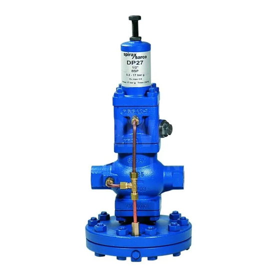
DP27, DP27E, DP27R and DP27Y
Pilot Operated Pressure Reducing Valves
Installation and Maintenance Instructions
2. General product
information
3. Installation
5. Maintenance
© Copyright 2016
IM-P470-03 CH Issue 7
1
Printed in GB
Advertisement
Table of Contents

Related Manuals for Spirax Sarco DP27


Summary of Contents for Spirax Sarco DP27
- Page 1 IM-P470-03 4700036/7 CH Issue 7 DP27, DP27E, DP27R and DP27Y Pilot Operated Pressure Reducing Valves Installation and Maintenance Instructions 1. Safety information 2. General product information 3. Installation 4. Commissioning 5. Maintenance 6. Spare parts 7. Fault finding © Copyright 2016...
- Page 2 IM-P470-03 CH Issue 7...
-
Page 3: Safety Information
Determine the correct installation situation and direction of fluid flow. iv) Spirax Sarco products are not intended to withstand external stresses that may be induced by any system to which they are fitted. It is the responsibility of the installer to consider these stresses and take adequate precautions to minimise them. - Page 4 1.9 Tools and consumables Before starting work ensure that you have suitable tools and / or consumables available. Use only genuine Spirax Sarco replacement parts. 1.10 Protective clothing Consider whether you and / or others in the vicinity require any protective clothing to protect against the hazards of, for example, chemicals, high / low temperature, radiation, noise, falling objects, and dangers to eyes and face.
- Page 5 1.11 Permits to work All work must be carried out or be supervised by a suitably competent person. Installation and operating personnel should be trained in the correct use of the product according to the Installation and Maintenance Instructions. Where a formal 'permit to work' system is in force it must be complied with. Where there is no such system, it is recommended that a responsible person should know what work is going on and, where necessary, arrange to have an assistant whose primary responsibility is safety.
- Page 6 2. General product information 2.1 General description DP27, DP27E, DP27G, DP27GY, DP27R and DP27Y pilot operated pressure reducing valves have bodies manufactured using SG iron.These products are not suitable for oxygen service. DP27 Suitable for steam or compressed air applications.
- Page 7 IM-P470-03 CH Issue 7...
- Page 8 The DP27E is limited to 10 bar g @ 190 °C. Note: DP27 has a variable rate conical pressure adjustable spring fitted providing a downstream pressure range of 0.2 - 17 bar g. DP27Y has a pressure spring with a range of 0.2 - 3 bar g.
- Page 9 190 °C @ 10 bar g For ASME 150, see A-B-C DP27G, DP27GY 120 °C @ 25 bar g Minimum operating temperature 0 °C Note: For lower operating temperatures consult Spirax Sarco DP27, DP27R and DP27Y 17 bar g Maximum differential pressure DP27G and DP27GY...
- Page 10 0.2 - 17 bar. DP27Y (Figure 1) The DP27Y is supplied as the DP27, but has a lower rate pressure adjustment spring for a downstream pressure range of 0.2 - 3 bar. Pressure setting adjustment screw...
- Page 11 DP27E The DP27E (Figure 2) is supplied as for the DP27 with Solenoid a control spring but the maximum pressure is limited valve to 10 bar g due to the addition of the solenoid valve. A solenoid operated valve is fitted in the pipe between the pilot valve and the main diaphragm chamber and is thus in series with the normal pilot valve.
- Page 12 See Section 3.6, page 13. Downstream isolating valve to provide no-load conditions for Float type setting pressure reducing valve Strainer steam trap DP27 and DP27E Float type Check valve steam trap Alternative for draining separator Steam supply Strainer Sight...
- Page 13 Q Steam supply Q Q See Section 3.6 Fig. 5 Two pressure reducing valves in parallel 3.3 Pipeline sizing The piping on both sides of the valve must be sized so that velocities do not exceed 30 m / s. This means that a properly sized valve will often be smaller than the connecting pipework.
- Page 14 1 m or 15 pipe diameters whichever is the greater. It should be arranged with a positive fall so that any condensate can drain away from the DP27. Where the size of the reduced pressure main makes it difficult to maintain a fall when entering the top of the main, the pressure sensing pipe may be connected in the side of the main.
- Page 15 Where a safety valve (C) is required to protect the system downstream of a DP27 and where a control valve is also being used downstream of the DP27, it is recommended that the safety valve is fitted downstream of the control valve rather than in between the DP27 and the control valve.
- Page 16 (Figure 8 and Figure 9) 1. Ensure that all connections are properly made and that all valves are closed. DP27R (Figure 9) DP27, DP27E and DP27Y (Figure 8) 2. Close all valves at reducing valve station, 2. Close all valves at reducing valve station, including the valve on the bypass line, if including valves on bypass line if fitted.
- Page 17 Steam flow Q Condensate Q See Section 3.6, page 11 return Fig. 8 Setting procedure sequence DP27, DP27E and DP27Y Optional bypass line (see Section 3.10) 2, 6 3, 7, 8 2, 9 Steam flow ...
- Page 18 Note: Before actioning any maintenance programme observe the 'Safety information' in Section 1. Warning: The body gasket (all DP27 derivatives) and actuating chamber gasket (DP27R) contains a thin stainless steel support ring which may cause physical injury if not handled and disposed of correctly.
- Page 19 5.2 How to renew the pilot filter element 1. Isolate the reducing valve and zero the pressure. 2. Unscrew the filter cap and carefully withdraw the filter element. 3. Replace the element and tighten the filter cap to 90 - 100 N m. Note: The gasket is re-usable.
- Page 20 5.4 How to renew the pilot valve assembly 6. DP27, DP27E and DP27Y Isolate the reducing valve and zero the pressure and proceed to unscrew the 4 off spring housing securing nuts and remove spring housing, bottom spring plate and diaphragms.
- Page 21 Table 1 Recommended tightening torques for spring housing/actuating chamber cover securing studs and nuts Size of valve Nut size Tightening torques DN15, DN20, DN25 and DN32 40 - 50 N m DN40 and DN50 45 - 55 N m IM-P470-03 CH Issue 7...
- Page 22 Isolate the actuating air supply and zero the pressure. 13. Unscrew the unions and release the pipework. 14. Unscrew the nuts. 15. DP27, DP27E and DP27Y Remove the pilot valve housing; complete with spring housing assembly. DP27R Remove the pilot valve housing, complete with air control block.
- Page 23 IM-P470-03 CH Issue 7...
- Page 24 Isolate the reducing valve and zero the pressure. DP27R Isolate the actuating air supply and zero the pressure. 23. DP27, DP27E and DP27Y Unscrew the nuts and remove: spring housing, bottom spring plate and old diaphragms. DP27R Unscrew the nuts and remove the air control block and old diaphragms.
- Page 25 5.7 How to renew or clean main diaphragms Isolate the reducing valve and zero the pressure. 27. Undo the long union nut and pull away. 28. Undo the M12 nuts and bolts. 29. Drop away the lower diaphragm chamber, the two diaphragms, diaphragm plate and the pushrod assembly.
- Page 26 31. Replace the diaphragm plate and pushrod assembly and loosely fit the lower diaphragm chamber on two bolts either side of the union connection to locate the spigot in the recess. 32. Bring the two new diaphragms together (where precoated sealant is applied this should face outwards) and slide into position.
- Page 27 5.8 How to service or renew the main valve and seat DP27, DP27E and DP27Y Isolate the reducing valve and zero the pressure. DP27R Isolate the actuating air supply and zero the pressure. 35. Unscrew the unions and release the pipework.
- Page 28 37. DP27, DP27E and DP27Y Remove the pilot valve housing, complete with spring housing assembly. DP27R Remove the pilot valve housing, complete with air control block. 38. Remove the main valve plus internal strainer screen and clean. 39. Remove the main valve spring and the main valve head. Clean to remove dirt or scale as necessary.
- Page 29 Table 2 Recommended tightening torques for main valve seat Size of valve Width across flats Tightening torques DN15 and DN15 LC 30 mm A / F (External) 110 - 120 N m DN20 36 mm A / F (External) 140 - 150 N m DN25 19 mm A / F (Inside)
- Page 30 55. Fit a new gasket. 56. Replace the internal strainer screen. 57. DP27, DP27E and DP27Y Assemble the pilot valve housing complete with spring housing assembly and tighten the nuts to the recommended torques shown in Table 1, page 21.
- Page 31 IM-P470-03 CH Issue 7...
- Page 32 5.9 How to service or renew the solenoid valve DP27E Depressurize the valve and turn off the electrical power supply. 59. Undo the retaining nut and slip the entire solenoid enclosure off the solenoid base and sub-assembly or plugnut / core tube sub-assembly. 60.
- Page 33 6. Spare parts Interchangeability of spares The following table shows how in certain sizes some parts are interchangeable. For example in the line headed 'Main diaphragm' the diaphragm used in the screwed valves ½" and ¾" is common to these sizes by the letter 'a', the letter 'c' indicates that one diaphragm is common to the DN40 and DN50 valves.
- Page 34 Always order spares by using the description given in the column headed 'Available spares' and state the size and type of the pressure reducing valve. Example: 1 - Main valve assembly for a Spirax Sarco DN25 DP27 pilot operated pressure reducing valve. IM-P470-03 CH Issue 7...
- Page 35 DP27E DP27R DP27, DP27R DP27Y DP27E IM-P470-03 CH Issue 7...
- Page 36 7. Fault finding 7.1 Preliminary procedure Before undertaking the following fault finding procedure, ensure the valve has been isolated and that upstream and downstream pressures are zero. Possible fault checks are given in a logical order below. 7.2 Downstream pressure zero or too low If downstream pressure drops below set pressure or is zero check the following: 1.
- Page 37 7.3 Downstream pressure too high If the pressure on the downstream side of the reducing valve has risen above the required set pressure check the following: 1. Downstream pressure sensing pipe blocked. Dismantle and blow through. 2. Control orifice (item 'P1' on page 29) blocked. Unscrew pipework from side of body and clean out.
- Page 38 IM-P470-03 CH Issue 7...
- Page 39 IM-P470-03 CH Issue 7...
- Page 40 IM-P470-03 CH Issue 7...
Need help?
Do you have a question about the DP27 and is the answer not in the manual?
Questions and answers