Table of Contents
Advertisement
Quick Links
Advertisement
Table of Contents

Summary of Contents for Spirax Sarco Hiter 85 Series
- Page 1 IM-P414-06-EN-ISS1 Oct. 2023 / Rev.01 85 Series Installation and Maintenance Manual 1. Warranty term 2. General safety information 3. Introduction 4. Installation 5. Maintenance 6. Action Of The Valve and Position by Failure 7. Part List IM-P414-06-EN-ISS1...
-
Page 2: Warranty Term
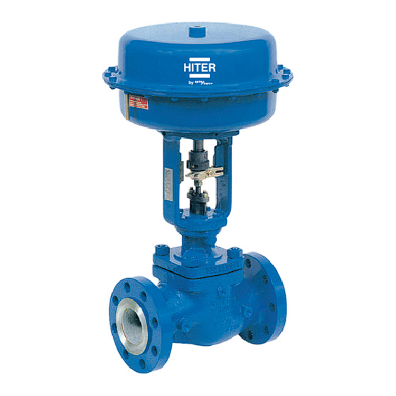
Hiter Controls only obligation with the Warranty Term is to repair or replace any product that we deem defective. Spirax Sarco reserves the right to inspect the product at the end customer's facility or request the return of the product with prepaid freight by the buyer. - Page 3 Viton seal, special care must be taken to avoid potential health hazards associated with decomposition/burning of this item. Additional Information Additional information and help is available worldwide at any Spirax Sarco service center. 3. Introduction The 85 Series check valve, which is considered a high-quality valve, provides excellent sensibility, fine control and easy adjustment, with very-reduced weight and size.
-
Page 4: Installation
4. Installation 4.1. The valve is inspected and shipped in a special packing with protection covers in the body openings. However, a carefully inspection should be performed in order to ensure there is no damage and that no material has penetrated in the valve during transportation or storage. 4.2. -
Page 5: Maintenance
4.13. For long-bonnet valves, in case of installation with thermal isolation, do not isolate the valve bonnet. Only the body must be isolated. Fig. 2 - 85 Series with loose flanges Fig. 3 - 85 Series with integral flanges 4.14. In continuous operation units, the installation must include a blockage and by-pass systems, constituted of three manual valves. - Page 6 The 85-01, 85-11, 85-51 and 85-61 valves have a seal ring (13) in the plug (6). Depending on the construction the seal-ring types are: O-ring PTFE strip or a two-piece graphite ring. If necessary, remove the stem (22) from the plug (6) and also remove the pin (8). The stem (22) only can be removed from the plug (6) in case of replacement.
- Page 7 If the bellows set removal is need. If the bellows set (35) removal from the plug (6) is need, remove the pin (8). In case of plug replacement (6), a new sealing set (35) should be installed. WARNING Never install a new plug (6) on a used sealing set. The plug installation requires a new bore for pin and, if the sealing set stem already has a bore, the threads shall be weakened.
- Page 8 Do not remove the guide bush (45) from the seat retainer (7) (figure 7) if the replacement is not necessary. The guide bush is pressed in the seat retainer. Remove the seat (4) and the seat gasket (5). In case of soft seal (figure 5) the seat is compounded of superior seat (4.3), seat ring (4.2) and inferior seat (4.1) (figure 5).
- Page 9 5.2. CLEANING, INSPECTION AND REPAIR All valve metallic parts must be cleaned using solvent and dried with compressed air after inspection. Those approved should be kept clean and very well protected up to the assembly. The oil protector application to the steel carbon non-painted parts is recommended. If there is a damage that can not be resolved by parts replacement and/or corrective actions, the valve should be returned properly assembled to HITER for general revision.
- Page 10 WARNING Never install a new plug (6) on a used stem. The plug installation requires a new bore for pin and, if the stem already has a bore, the threads shall be weakened. However a used plug may be assembled with a new stem. Enter the plug set (6) and the stem (22) in the cage (7).
- Page 11 WARNING Never install a new plug (6) in a used stem sealing seat. The plug installation requires a new bore for pin and if the sealing set stem already has a bore, the threads shall be weakened. However, a used plug can be assembled on a new sealing set. Assemble the plug set (6), sealing set (35) and bellows housing (34) entering the plug (6) in the cage (7).
- Page 12 In some configurations the plug (6) does not pass by the seat retainer (7) (figure 7). In this case pass the seat retainer (7) by the stem (22). Assemble the seat retainer (7) or the set including the seat retainer (7) (figure 7) and the plug (6) with the stem (22) in the body (1).
- Page 13 WARNING Never install a new plug (6) in a used stem sealing set. The plug installation requires a new bore for pin and, if the sealing set stem has already a bore, the threads shall be weakened. However, a used plug can be mounted in a new sealing set. Assemble the set including seat retainer (7) (figure 7), plug (6), sealing set (35), bellow housing (34), gaskets and cage adapter (when applicable) on the body (1).
-
Page 14: Part List
Thread the stem (22) in the sealing set (35). Place the bonnet gasket (37) on the bellow set (35). Assemble the bonnet (14) over the bellow housing (34). Tight the nuts (36) and the studs (38) alternately in the adverse crossed sequence. As reference for clean threads, use the torques presented in table 1 (page 6). - Page 15 More information on our website in English: Darci Rocha International Sales Manager Telephone: +55 15 3225-0355 Cell phone/WhatsApp: +55 15 99171-1448 E-mail: darci.rocha@br.hiter.com hiter.com.br/en IM-P414-06-EN-ISS1...


Need help?
Do you have a question about the Hiter 85 Series and is the answer not in the manual?
Questions and answers