Table of Contents
Advertisement
Quick Links
1.753.000.079
IM-D344-01
BR Rev.03
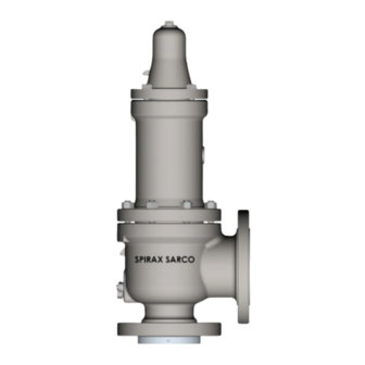
SV80H
Safety and Relief Valves
Installation and Maintenance Guide
UV
1. Warranty term
2. General Safety
Information
3. Introduction
4. Terms and Definitions
5. Handling and Storage
6. Installation
7. Maintenance and Testing
8. Trouble Shooting
IM-D344-01 BR Rev. 03
1
Advertisement
Table of Contents

Subscribe to Our Youtube Channel
Related Manuals for Spirax Sarco SV80H


Summary of Contents for Spirax Sarco SV80H
- Page 1 1.753.000.079 IM-D344-01 BR Rev.03 SV80H Safety and Relief Valves Installation and Maintenance Guide 1. Warranty term 2. General Safety Information 3. Introduction 4. Terms and Definitions 5. Handling and Storage 6. Installation 7. Maintenance and Testing 8. Trouble Shooting IM-D344-01 BR Rev. 03...
-
Page 2: Warranty
Spirax Sarco only obligation with Warranty is to repair or replace any product that we consider defective. Spirax Sarco reserves the right to inspect the product in customer installations or request the return of the product with freight prepaid by the buyer. -
Page 3: General Safety Information
Allow time for temperature to normalize after isolation to avoid danger of burns. Tools and consumables Before starting work ensure that you have suitable tools and/or consumables available. Use only genuine Spirax Sarco replacement parts. Tools and consumables Before starting work ensure that you have suitable tools and/or consumables available. Use only genuine Spirax Sarco replacement parts. - Page 4 See Item 5. Disposal Unless otherwise stated in the Installation and Maintenance Instructions, this product is recyclable and no ecological hazard is anticipated with its disposal providing due care is taken. IM-D344-01 BR Rev. 03...
- Page 5 Item Description Body Pipe Plug Lock Screw Gasket Lock Screw Body Studs Nozzle** Nozzle Gasket** Blowdown Ring Disc** O' Ring ** Retainer Screw for O'Ring Disc Disc Holder Bellows Gasket Bellows** Guide Gasket** Guide Stem Retainer Spindle Spring Washer Spring** Bonnet Hex Nut (Body) Adjusting Screw...
-
Page 6: Terms And Definitions
Safety Relief Valves SV80H, but does not replace the expertise and experience required for the execution of repair and maintenance of valves. Classifications applicable to the identification of the relevant parts of the model are defined in SV80H drawings on page 5. - Page 7 4.8 Relief Pressure It is the pressure at which the valve relieves the maximum capacity for which was dimensio- ned. It is equal to the opening pressure plus overpressure. 4.9 Overpressure The pressure increase over the set pressure of the relieving device. Overpressure is expres- sed in pressure units or as a percentage of set pressure.
-
Page 8: Handling And Storage
4.17 Simmer The audible or visible escape of compressible fluid between the seat and disc of a pressure relief valve which may occur at an inlet static pressure below the set pressure prior to opening. 4.18 Chatter Abnormal condition characterized by rapid openings and closings in succession, causing serious damage to the valve. - Page 9 NORMAL LEVEL LIQUID FIG. 02 It is recommended that valves be inspected prior to installation. Calibration and seat tightness should be verified, for this, a suitable testing bench with compressed air or inert gas and water shall be used. The tests shall be performed by qualified professionals, in the presence of an equipment inspector.
- Page 10 Nº of Tightening pattern Studs 1-3-2-4 1-4-2-5-3-6 1-5-3-7 → 2-6-4-8 1-7-4-10 → 2-8-5-11 → 3-9-6-12 1-9-5-13 → 3-11-7-15 → 2-10-6-14 → 4-12-8-16 TABLE 01 • Install discharge piping using the same procedures used in the valve installation. • Prior to completing the installation, a visual check should be made to ensure that the valve lifting lever is free to operate.
- Page 11 STOP VALVE VESSEL VESSEL FIG. 03 • Header nozzle corners must be rounded to a radius of not less than 1/4 of the opening diameter. • The safety and relief valve inlet should not be positioned at the end of a horizontal pipe in which there is normally no flow.
- Page 12 • The calculation of reaction force during valve relief is responsibility of the designer of the vessel and / or piping. Spirax Sarco can provide this information only as technical assistance and does not assume any responsibility for its application.
-
Page 13: Outlet Piping
• External loads resulting from support systems and poorly designed piping may be the cause of excessive stresses and distortion in the valve and inlet pipe. The accumulation of stress may cause the valve to malfunction or leak. • Vibrations in the inlet piping systems may cause leaks, premature wear of certain parts of the valve and / or pipe failure by fatigue. -
Page 14: Maintenance And Testing
This is especially recommended for long pipelines. 7. Maintenance and Testing • SV80H valves model can be easily disassembled for inspection, maintenance or parts repla- cement. • The period for maintenance of each valve shall meet at least the requirements of NR13 Standard for the protected equipment;... - Page 15 7.1.3 Note the dimension A, as shown in Figure 06, this information will be necessary to position the adjusting screw (24) when reassembling the valve. FIG. 06 7.1.4 Remove the lock screw (04) of the blowdown ring (08) and the gasket (03). If the blowdown (2.13) needs to be restored after reassembly, the position of the blowdown ring relative to the disc holder must be observed.
- Page 16 7.1.10 Remove the guide from the disc holder. 7.1.11 In balanced valves, remove the bellows (14) from the disc holder. The bellows is attached to the disc holder by screw thread. Using a 3 or 4 clamps mandrel, attach the bellows skirt ring to the mandrel (Fig.
- Page 17 7.1.15 Remove the nozzle (06) from the body (01). The nozzle is mounted to the body by right-hand threads. Using a 3 or 4 clamps mandrel, hold the nozzle in the mandrel and loosen it from the body using a bar or pipe (Figure 07) and rotating the body in an counterclockwise direction.
- Page 18 7.1.16 The nozzle may also be removed from the body using a large plumber wrench (Figure 08). PLUMBER CHAVE DE CANO WRENCH NOZZLE BOCAL BODY CORPO CLAMP (03) MORDENTE (03) MANDREL MANDRIL BASE SUPORTE FIG. 08 7.1.17 The valve is ready for cleaning and inspection. 7.2 Cleaning The parts should be cleaned using sandpaper and a suitable solvent.
- Page 19 7.3 Inspection Carefully inspect each internal valve component, noting any defects such as cracks, corrosion, ex- cessive wear or other mechanical defects. For the following parts some details must be observed: 7.3.1 Nozzle (06) Look for cuts, nicks or other damage on the seating surface. The threads of the blo- wdown ring and of fixation to the body must be in good condition without abrasions, tears or other damage.
- Page 20 Metric units, mm Nozzle Metal / Metal Seat. Class 158,8 164,4 164,6 171,0 43,8 172,0 178,4 16,4 TABLE 02 IM-D344-01 BR Rev. 03...
- Page 21 7.3.2 Disc (09) Look for cuts, nicks or other damage on the seating surface. Check the disc for defects such as cracks (w/ dye penetrant) and/or severe corrosion. The disc can be re-machined, if necessary, up to the dimension A minimum (Figure 10) shown in Table 03. Dimension C should be redone when the disc is re-machined.
- Page 22 7.3.5 Guide (17) Inspect the guide inside diameter for galling, and make sure the inside surface is smooth and there is no corrosion on the gasket sealing areas. If some imperfection is found, the surfaces can be polished with emery cloth. If it is badly damaged, the guide should be replaced.
- Page 23 7.4 Lapping SV80H valves have its seating surfaces (nozzle and disc) lapped in an automatic lapping machi- ne, which ensures the best tightness characteristics. In maintenance services, where de lapping machine is not available, a cast iron block or another perfectly flat surface (e.g. glass) can be used, performing lapping according to the conventional method (Figure 11).
- Page 24 7.5 Assembly SV80H valves can be easily reassembled, without the need of any special tools. Make sure that the internal parts are clean, especially the seating surfaces and the guided parts. Replace the gaskets. Use a lubricant with anti-seize properties in all threads and bearing surfaces.
- Page 25 Torque required for Each Round of Pathern Riquired Bolts Torque in Nm Key grip Key grip Key grip Key grip Key grip TABLE 06 7.5.10 Thread the locknut (25) on the adjusting screw (24) and install the assembly in the bonnet.
- Page 26 • Liquid N° of Notches Orifice notches notches notches notches notches notches notches notches notches notches TABELA 07B 7.5.12 The valve is ready for final setting and testing. 7.6 Bench Testing and Setting Although the valve can be adjusted in the service facility, it is recommended that the setting of the valve, and checking of the seat tightness, to be done on a test bench.
- Page 27 7.6.5 For compressible fluids, the opening pressure is defined as the pressure at which the valve opens abruptly (Pop) and not the one that leakage start (simmer) (4.17) . 7.6.6 For liquids, the opening pressure is indicated by the first continuous flow of water through the valve outlet.
- Page 28 7.6.13 Install cap (29) and lever system, if any. 7.6.14 Back pressure testing for joint leakage. • Apply air or nitrogen to the body drain or to the valve outlet. Seal all other openings. Test pressure should be the actual valve back pressure or 2.1 barg, wichever is greater. The following components shall be examined for leakge during back pressure testing: •...
-
Page 29: Hydrostatic Testing
SPINDLE NUT SPINDLE NUT SPINDLE TEST NUT SPINDLE TEST NUT FORK LEVER CAP SCREW LEVER OPEN LEVER PACKED LEVER FIG. 13 FIG. 13 7.9 Hydrostatic Testing • When hydrostatic tests are required after installation of Safety and Relief Valves, these should be removed and replaced by a blind fl ange. -
Page 30: Troubleshooting
8. Trouble Shooting KEYWORD PROBLEM EFFECT DIAGNOSIS CORRECTIVE ACTION The PSV is oversized for the installation Check the required capacity and - The flow is less than 25% of the replace PSV if necessary required capacity Redesign inlet piping so that the The inlet piping is of excessive length pressure drop is less than 3% of the set pressure CHATTER CHATTER THE VALVE WILL BE DAMAGED Increase inlet piping so to at least Inlet piping undersized for PSV inlet size of PSV The outlet piping is of excessive Redesign outlet piping so that length back pressure doesn't build up - Built up back pressure Outlet piping undersized for PSV Increase outlet piping to at least - Built up back pressure outlet size of PSV Adjust PSV to compensate the Misreading the PSV nameplate temperature and/or back - Back pressure and temperature pressure, according to the nameplate Ring in an incorrect position Adjusting ring and engage locking - Locking pin may not be engaged Disassemble PSV and inspect all... - Page 31 Notes IM-D344-01 BR Rev. 03...
- Page 32 Notes IM-D344-01 BR Rev. 03...
- Page 33 Sales Branches Porto Alegre Salvador Av. Inconfidência, 71 sala 2 - Centro Rua André Luiz Ribeiro da Fonte, 24 CEP: 92020-320 Salas 202/203 Canoas - RS Vilas do Atlântico Fone: (051) 3342-5577 CEP: 42700-000 E-mail: filial.portoalegre@br.spiraxsarco.com Lauro de Freitas - BA Fone: (71) 3379-7701 Belo Horizonte email: filial.salvador@br.spiraxsarco.com...
Need help?
Do you have a question about the SV80H and is the answer not in the manual?
Questions and answers