Advertisement
Table of Contents
- 1 Table of Contents
- 2 Safety Notice
- 3 Features and Principles of Measurement
- 4 Instrument Layout
- 5 Specifications
- 6 Functions
- 7 The Nature of Insulation Resistance
- 8 Preparation for Measurement
- 9 Insulation Resistance Testing
- 10 Continuity Testing
- 11 General
- 12 Battery and Fuse Replacement
- 13 Servicing & Calibration
- Download this manual
Advertisement
Table of Contents

Subscribe to Our Youtube Channel
Related Manuals for Kewtech KT35


Summary of Contents for Kewtech KT35
- Page 1 KEWTECH KT35 digital multi function tester Instruction manual...
-
Page 2: Table Of Contents
Tester. 1.1 This instrument must only be used by a competent trained person and in strict accordance with the instructions. Kewtech will not accept liability for any damage or injury caused by misuse or non-compliance with instructions or safety procedures. - Page 3 (broken test leads, cracked case, display faulty, inconsistent readings, etc) do not attempt to take any measurements. Return to Kewtech for rectification. 1.5 Never replace the protective fuse inside the instrument with any other than the specified or approved equal (0.5A/600V) fast acting ceramic to IEC127.
-
Page 4: Features And Principles Of Measurement
1.14 Always keep your hands and fingers behind finger guards on test leads used with this instrument. For safety reasons always use the accessories approved by Kewtech. The use of other accessories is prohibited as they may not have the same safety features built in. - Page 5 200mA continuity short circuit test current 1mA test current at the minimum load on insulation ranges Bar graph indicates test voltage-rise and decay can be observed during insulation tests Warning of external voltage presence ‘Press to test’ button with lock down feature. Releasing the test button automatically discharges the capacitance of a circuit under test Auto null feature...
- Page 6 connection to the circuit under test is essential to avoid mea- surement errors. Circuits connected in parallel to the circuit under test may also effect the accuracy of the measurement. Possible insulation resistance measurement errors may be caused by the circuit under test being wet and/or dirty. Errors may also occur when testing large installations where the insu- lation resistances may effectively be in parallel.
-
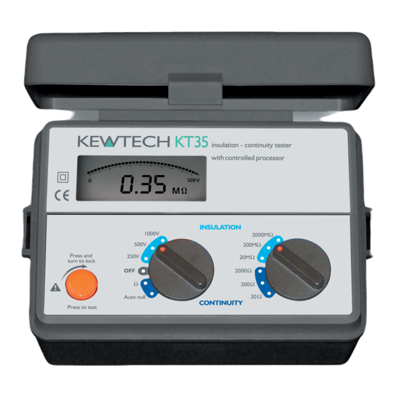
Page 7: Instrument Layout
Instrument layout 1 Crocodile Clip 2 Prod 3 Range Switch 4 Function Switch 5 Test Button 6 LCD Display... -
Page 8: Specifications
Specifications Insulation Resistance Measurement Specification Test Voltage 250V 500V 1000V 0 -20M Ω 0 -20M Ω 0 -20MΩ Measuring Ranges 0 -200M Ω 0 -200M Ω 0 -200MΩ 0 -2000M Ω 0 -2000M Ω 0 -2000MΩ Nominal Output 250V DC min. 500V DC min. 1000V DC min. Voltage (UN) at 0.25MΩ... - Page 9 Insulation Resistance Operating Error Range Operating Range Compliant with EN 61557-2 Operating Error 20MΩ 0.2MΩ to 20MΩ 200MΩ 2MΩ to 200MΩ 2000MΩ 20MΩ to 1000MΩ Continuity Resistance Operating Error Range Operating Range Compliant with EN 61557-4 Operating Error 20Ω 0.2Ω to 20Ω 200Ω...
-
Page 10: Functions
250V Range 0.25MΩ approx.1200 times or more 500V Range 0.5MΩ approx.1200 times or more 1000V Range 1MΩ approx. 400 times or more 20Ω Range 1Ω approx. 300 times or more Applied Standards Operation: EN 61557-1/2/4 Safety: EN61010 Cat.III 300V Protection: IEC60529 (IP40) Accessories ACC020... -
Page 11: The Nature Of Insulation Resistance
matically subtracts the test lead resistance before displaying the real continuity resistance value. A full description of how this feature can be used will be found in paragraph 9.2. The Nature of Insulation Resistance Live conductors are separated from each other and from earth- ed metal by insulation, which ensures that the current flowing between conductors and to earth is kept to an acceptably low level. - Page 12 6.2 Conduction Current The resistance of the insulation is not infinite, so a small current flows through it. Ohms's Law applies, so the leakage current can be found from: applied voltage (V) Leakage Current (µA) = insulation resistance (MΩ) Insulation (acting as resistance) Conductors Resistance effect 6.3 Surface Leakage Current...
- Page 13 The KT35 automatically connects a discharge resistor across the cir- cuit when the test button is released to provide a path for dis- charge current.
-
Page 14: Preparation For Measurement
The circuit is live and should be de-energised before further testing. The KT35 indicates the presence of external AC voltage on the LCD by showing a flashing symbol and the actual value... -
Page 15: Continuity Testing
The display will show the resistance of the test leads. The KT35 has an auto null function which enables the tester to automatically subtract this resistance before displaying the sys- tem continuity resistance. To enable this function, turn the func- tion dial to the Auto null position whilst still pressing the test button and shorting the leads. -
Page 16: General
9.3 Connect the test leads to the circuit under test. Ensure the circuit is not live by checking that the live circuit bleeper does not sound. The KT35 will indicate the value of external AC voltage (see section 8.3). Note: On the 20Ω range the end of test bleep has a lower tone for resistances less than approx. -
Page 17: Servicing & Calibration
12 month period. When the unit is due for re-cal- ibration, return to Kewtech marked for the attention of the cal- ibration department and be sure to include all accessory leads... - Page 18 Kewtech reserve the right to improve specifications and designs without notice and without obligations.
- Page 19 Case, strap, shoulder-pad and test lead pouch assembly Assemble the shoulder strap through the case lugs and the test lead pouch in the following sequence: 1 Pass the strap down through the first lug, under the case and up through the other lug. 2 Slide the shoulder pad onto the strap 4 Pass the strap through the buckle,...
- Page 20 Distributor Kewtech Corporation Limited 76 St. Catherine’s Grove Lincoln LN5 8NA KEWTECH www.kewtechcorp.com 92-1614 04-03...
Need help?
Do you have a question about the KT35 and is the answer not in the manual?
Questions and answers