Sign In
Upload
Download
Add to my manuals
Delete from my manuals
Share
URL of this page:
HTML Link:
Bookmark this page
Add
Manual will be automatically added to "My Manuals"
Print this page
×
Bookmark added
×
Added to my manuals
Manuals
Brands
Kewtech Manuals
Test Equipment
KT41
Instruction manual
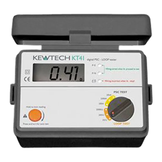
Kewtech KT41 Instruction Manual
Digital multi function testers
Hide thumbs
1
Table Of Contents
2
3
4
5
6
7
8
9
10
11
12
13
14
15
16
17
18
19
20
21
22
23
page
of
23
Go
/
23
Contents
Table of Contents
Bookmarks
Advertisement
Quick Links
1
Features and Principles of Measurement
Download this manual
KEWTECH
KT41/KT42
digital multi function testers
Instruction manual
Table of
Contents
Previous
Page
Next
Page
1
2
3
4
5
Advertisement
Need help?
Do you have a question about the KT41 and is the answer not in the manual?
Ask a question
Questions and answers
Related Manuals for Kewtech KT41
Test Equipment Kewtech KT45 Instruction Manual
Digital loop psc tester with anti trip technology (27 pages)
Test Equipment Kewtech KT400 Operating Instructions Manual
Loop impedance & psc / pfc tester (7 pages)
Test Equipment Kewtech KT42 Instruction Manual
Digital multi function testers (23 pages)
Test Equipment Kewtech KT72 User Manual
Pat tester with auto test sequence (30 pages)
Test Equipment Kewtech KT1780 Instruction Manual
Voltage tester (13 pages)
Test Equipment Kewtech KT61 Instruction Manual
Digital multi fuction tester (28 pages)
Test Equipment Kewtech KT1710 Manual
Voltage tester (7 pages)
Test Equipment Kewtech KTD50 User Manual
Digital rcd tester / tests rcds, mains voltage and polarity (12 pages)
Test Equipment Kewtech KT77 Instruction Manual
Portable appliance tester (53 pages)
Test Equipment Kewtech KT35 Instruction Manual
Digital multi function tester (20 pages)
Test Equipment Kewtech KT63 PLUS Operating Instructions Manual
Multifunction installation tester (33 pages)
Test Equipment Kewtech KT63DL Operating Instructions Manual
Multifunction installation tester (24 pages)
Test Equipment Kewtech KT1795 Instruction Manual
Current & voltage tester (12 pages)
Test Equipment Kewtech KT500 Operating Instructions Manual
Rcd tester (7 pages)
Test Equipment Kewtech KT63 Operating Instructions Manual
Multifunction installation tester (13 pages)
Test Equipment Kewtech KT31 Instruction Manual
Digital multi function tester (15 pages)
This manual is also suitable for:
Kt42
Print
Rename the bookmark
Delete bookmark?
Delete from my manuals?
Login
Sign In
OR
Sign in with Facebook
Sign in with Google
Upload manual
Upload from disk
Upload from URL


Need help?
Do you have a question about the KT41 and is the answer not in the manual?
Questions and answers