Advertisement
Advertisement

Related Manuals for Kewtech KT45


Summary of Contents for Kewtech KT45
- Page 1 KEWTECH KT45 digital LOOP PSC tester with Instruction manual...
-
Page 2: Table Of Contents
General Battery Replacement Servicing & Calibration The KT45 incorporates Anti Trip Technology (ATT) which electronically by-passes most RCDs at Distribution Boards. This saves time and money by not having to take the RCD out of circuit during testing and is a safer procedure to follow. -
Page 3: Safety Notice
Tester. 1.1 This instrument must only be used by a competent trained person and in strict accordance with the instructions. Kewtech will not accept liability for any damage or injury caused by misuse or non-compliance with instructions or safety procedures. - Page 4 1.12 Replace worn and/or damaged leads with new ones approved by Kewtech immediately. Only use accessories recommended by Kewtech as they are designed to work with the tester. The use of any other items is prohibited as they may not have the same safety features built in, and may degrade performance.
-
Page 5: Features
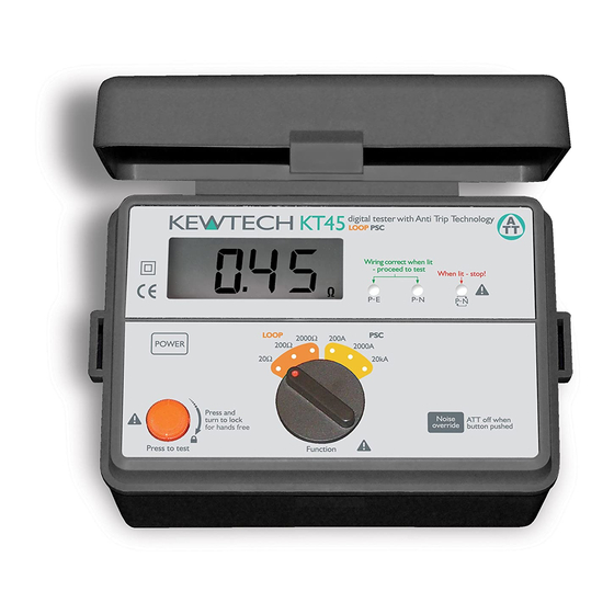
2 Features 2-1 Instrument layout Fig 1 1..LCD 2..Power Switch 3..Test Button 4..Function / Range Switch 5..Wiring Check LEDs LED indication of correct polarity is that the P-E and P-N LEDs are lit. P and N are reversed when the reverse LED is lit. - Page 6 2-2 Accessories ▲KAMP11UK mains test lead with IEC Connector ▲ACC016E Distribution board fused test lead (Fuse: 10A/600V fast acting ceramic) ▲Test lead carry pouch KAMP11UK for hands free Black phase neutral ACC016E Green earth for hands free Fig 3...
- Page 7 2-3 Features ▲ ATT In the ATT mode, LOOP (Anti Trip Technology) measurement can be done without tripping RCDs rated at 30mA or more. ▲ Wiring Check Three LEDs indicate if the wiring of the circuit under test is correct. ▲...
- Page 8 2-4 Measurement specification Loop impedance Nominal test current at Measuring Intrinsic Range 0Ω external loop: range accuracy Magnitude/Duration 20Ω 0.00-19.99Ω 25A/10ms 200Ω 0.0-199.9Ω 2.3A/20ms ±(3%rdg+4dgt) 2000Ω 0-1999Ω 15mA/360ms 20Ω 0.00-19.99Ω (ATT) (*1)L-N<20Ω P-N:25A/30ms ±(3%rdg+6dgt) 200Ω 0.0-199.9Ω N-E:11mA/approx. 2s (ATT) (*1)L-N<20Ω Prospective Short-circuit Current Nominal test current at Measuring...
- Page 9 Voltage Measuring range Intrinsic accuracy 100-300V (*2): ±(2%rdg+4dgt) (*2): The voltage and "V L- PE Hi" is displayed on the LCD alternately when the voltage is 260V or more and under 300V. 2.5 Reference conditions Ambient temperature: 23±5℃ Relative humidity: 60±15% Nominal system voltage 230V, 50Hz...
- Page 10 2-6 Operating error Loop impedance(IEC61557-3) Operating range compliant Range with EN61557-3 operating error 20Ω 0.35 to 19.99Ω 200Ω 20.0 to 199.9Ω 2000Ω 200 to 1999Ω The influencing variations used for calculating the Operating error are: Ambient temperature: 0゜ and 35℃ Phase angle: 0゜...
- Page 11 Input voltage greater than 'VLP-E Hi' and 260V indication: voltage(alternating) Input voltage greater than 'VLP-E Hi' 300V indication: Over temperature indication Low battery indication ATT mode indication Noise indication (ATT Mode) 2.8 Applied standards Instrument operating IEC/EN61557-1,3(1997) standard Safety standard IEC/EN 61010-1(2001), CATIII (300V) -Instrument IEC/EN 61010-031(2001),...
-
Page 12: Principles Of Measurement
KT45 takes a current from the supply and measures the difference between the unloaded and loaded supply voltages. From this difference it is possible to calculate the loop resistance. - Page 13 For TN systems the earth fault loop impedance is the sum of the following impedances. ▲Impedance of the power transformer secondary winding. ▲Impedance of the phase conductor from the power transformer to the location of the fault. ▲Impedance of the protective conductor from the fault location to the power transformer.
- Page 14 When the protective device is a residual device (RCD), Ia is the rated residual operating current IΔn. For example in a TT system protected by an RCD the maximum RA values are as follows: Rated residual operating cur- 10 1000 rent I n mA Ra (at 50V)Ω...
- Page 15 Fig 6 For this example the maximum value is 1667Ω, the loop tester reads 12.74Ω and consequently the condition RA is < _ 50/Ia is met. It also important to test the operation of the RCD using a dedicated RCD tester in accordance with the international standard IEC60364 for a TN system.
- Page 16 Note: ▲When the protective device is a residual current device (RCD), Ia is the rated residual operating current I n. For instance in a TN system with a nominal mains voltage of Uo = 230V protected by type gG fuses the Ia and maximum Zs values could be: Rating Disconnecting Time 5s Disconnecting Time 0.4s...
- Page 17 The maximum value of Zs for this example is 2.1Ω (16 amp gG fuse, 0.4 seconds). The loop tester reads 1.14Ω consequently the condition Zs < _ Uo/Ia is met. 3.2 Principles of the measurement (line impedance and prospective short circuit current) Line impedance on a single phase system is the impedance measured between phase and neutral terminals.
-
Page 18: Operating Instructions
Always inspect your test instrument and lead accessories for abnormality or damage-If abnormal conditions exist DO NOT PROCEED WITH TESTING. Have the instrument checked by Kewtech. (1) Operate the Power button and turn on the instrument. Turn the Function switch and set it to any range at the LOOP or PSC. - Page 19 circuit under test, "no" is displayed on the LCD and no measurement can be made. In this case, disable the ATT function and make measurement. Be aware that if the ATT mode is disabled, RCDs may trip. ▲ ATT mode is automatically enabled after one measurement when making a measurement with ATT mode disabled.
- Page 20 4.2 Measurement of Loop impedance a. Loop Impedance at Mains Socket Outlet Connect the mains lead to the IEC socket of the instrument. Plug the molded plug of the mains lead into the socket to be tested. Carry out the initial checks. Press the test button.
- Page 21 c. Loop impedance at 3-phase equipment Use the same procedure as (b) ensuring only 1-phase is connected at a time i.e. FIRST test-red prod to phase 1, black prod to neutral, green crocodile clip to earth; SECOND test-red prod to phase 2, black prod to neutral, green crocodile clip to earth etc.
- Page 22 the green crocodile clip to the neutral of the system Carry out the initial checks Press the test button. A beep will sound as the test is conducted and the value of PSC will be displayed. It is good practice to disconnect the phase lead first Note: PSC function has a power factor correction of 0.84.
-
Page 23: General
5.4 If at any time during testing there is a momentary degradation of reading, this may be due to excessive transients or discharges on the system or local area. Should this be observed, the test should be repeated to obtain a correct reading. If in doubt, always contact Kewtech. -
Page 24: Battery Replacement
6 Battery replacement When the display shows the low battery indication, ( disconnect the test leads from the instrument. Remove the battery cover and the batteries. Fig 9 DANGER Never open the battery compartment cover while making measurement. To avoid possible electrical shock, disconnect the test probe before opening the cover for battery replacement. -
Page 25: Servicing & Calibration
7 Servicing and Calibration If this tester should fail to operate correctly, return it to Kewtech marked for the attention of the Service Department. stating exact nature of fault. Make sure that: a. operating instructions have been followed b. leads have been inspected c. - Page 26 Case, strap, shoulder-pad and test lead pouch assembly Assemble the shoulder strap through the case lugs and the test lead pouch in the following sequence: 1 Pass the strap down through the first lug, under the case and up through the other lug. 2 Slide the shoulder pad onto the strap 4 Pass the strap through the buckle,...
- Page 27 Distributor Kewtech Corporation Limited St. Catherine’s Grove Lincoln LN5 8NA KEWTECH www.kewtechcorp.com 92-1650 05-02...
Need help?
Do you have a question about the KT45 and is the answer not in the manual?
Questions and answers