Table of Contents
Advertisement
Advertisement
Table of Contents

Related Manuals for Kewtech KT63DL


Summary of Contents for Kewtech KT63DL
- Page 1 KT63DL Multifunction Installation Tester Operating Instructions kewtechcorp.com...
-
Page 2: Table Of Contents
Index Safety information and explanation of symbols used ......3 Features of the KT63DL ..............5 Special Polarity Test Function............6 Audible tones ................7 Overview of the switches and LCD ..........8 Test lead inputs ................9 Continuity Test Function ..............10 Continuity Test Procedure ..............10 Lead Nulling ................... -
Page 3: Safety Information And Explanation Of Symbols Used
Safety information and explanation of symbols used Because the KT63DL is a multifunction tester used for testing both live and dead circuits there are different safety issues that apply to the individual functions. Before using your KT63DL please read these instructions paying particular attention to the general safety warnings below and those at the start of each section. - Page 4 Alkaline batteries type AA / LR6 in accordance with the polarity shown The KT63DL complies fully with the requirements of EN61010. The following table details the operating ranges for the individual functions compliant with the performance requirements of EN61557.
-
Page 5: Features Of The Kt63Dl
The KT63DL is packed with design features that maximise both convenience and safety. These include: Large display To give the clearest results the KT63DL uses a large auto-backlit LCD which makes reading the test results easy even when used in poorly lit areas. Auto shut down To preserve battery life when not in use the KT63DL incorporates an Auto-Off function that powers the unit down after three minutes of inactivity. -
Page 6: Special Polarity Test Function
Special polarity test function It is a little known fact that a system can be reverse wired with Line (Phase) to earth/ neutral and earth/neutral to Line (Phase). The sockets will all work and conventional loop testers will show and test that everything is correct despite this very dangerous wiring condition. -
Page 7: Audible Tones
Audible tones A simple selection of audible tones is used to supplement the visual display. These help the user by providing intuitive feedback during testing. In addition to warning about dangerous or unstable supply conditions they provide a very quick confirmation that the measurement process is taking place and, upon completion of the test, a warning if the results are likely to be regarded as a failure. -
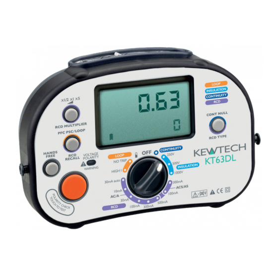
Page 8: Overview Of The Switches And Lcd
Overview of the switches and LCD Test lead inputs multiplier PFC-Loop Continuity RCD Recall Null Button RCD type Hands free selector Button Test Button Polarity test Function Selector touch pad area The Primary display of the large LCD shows the result of the test being conducted. At the same time a secondary display area shows supporting information e.g. -
Page 9: Test Lead Inputs
Test lead inputs The test lead input/ output terminals are separated into two groups by the clear sliding interlock cover. When slid to the left (figure 1) the interlock cover exposes only the Blue/Black terminal (marked -) and the Brown/Red terminal (marked +). These are used for the Continuity and Insulation test functions. -
Page 10: Continuity Test Function
Traditionally this would mean that the resistance of the test leads would have to be measured and manually deducted from each subsequent reading. The KT63DL has a handy feature known as lead nulling that does this calculation for you. -
Page 11: Hands Free Continuity Testing
The word ‘NULL’ will now appear in the display and all subsequent continuity tests conducted by pressing the Orange test button will automatically deduct this value before displaying the result. To confirm that this is working press the Orange test button with the prod tips still connected together and the display should show zero resistance. -
Page 12: Insulation Test Function
Connect the Brown test probe to the phase conductor and the Blue probe to the other conductor being tested and press the Orange test button. During Insulation testing the KT63DL will audibly indicate that measurement is being made by emitting a steady beeping sound. -
Page 13: Hands Free Insulation Testing
Hands Free Insulation testing To enable the hands free feature simply press the HANDS FREE button once, The ‘HANDSFREE’ annunciator will appear flashing on the LCD and will continue to do so until cancelled by a further press of the HANDS FREE button or by changing the function selector switch. -
Page 14: Loop Test Functions
The KT63DL Loop test function has 2 modes for Loop testing that allow the user to conduct the most accurate test possible whether or not the circuit under test is protected by an RCD. -
Page 15: Pfc/Psc
This will reduce the chances of the RCD tripping as a result of combined leakages. PFC/PSC In both Loop test modes the KT63DL will also display the supply voltage and at the touch of the PFC button the PFC/PSC will be displayed. Test lead configuration The KT63DL Loop test function can be used with 2 different types of connecting lead. -
Page 16: Lead Configuration For No-Trip Testing
Lead configuration for No-Trip testing In No-trip mode the tester can be used with the mains lead KAMP12 when testing at 13A socket outlets, or the distribution board lead set ACC063 for testing at other points in the circuit. In No-trip mode the 3 colour coded prods/crocodile clips of the test lead should be connected to the corresponding Line, Neutral and Earth terminals. -
Page 17: Loop Test Procedures
Mains supply wiring and voltage test When first connected to a mains supply the KT63DL will automatically conduct a safety test to ensure that the Live, Neutral and Earth conductors are all connected correctly and that the supply voltage is in the acceptable range (207-253V). -
Page 18: High Current Test (Ze)
High current test (Ze) The high current should only be conducted with the distribution board test lead set ACC063 configured in 2 wire mode. Do not use this function with the KAMP12 mains lead or the distribution lead set in 3-wire configuration. Rotate the function selector to the HIGH position. -
Page 19: Rcd Test Function
KT63DL will conduct all six required tests at the single touch of a button. Pass or Fail result In addition to displaying the time taken for the RCD to trip the KT63DL will also indicate whether it has passed or failed the test requirements of the BS7671. -
Page 20: Ramp Test
The KT63DL takes care of this for you by alternating the start point of consecutive tests at any given setting. If for example you have selected a test at the rated trip current (x1) of a... -
Page 21: Rcd Test Procedure
Connect the 4mm plugs of the chosen test lead to the corresponding L, N & E terminals of the KT63DL and connect the other end to the socket or circuit terminals under test. If using the distribution board test lead set ACC063 observe the correct polarity by connecting the Brown probe to the Live conductor, Blue to Neutral and Green to Earth. -
Page 22: 30Ma Automatic Test
The main display shows that the fault current was applied for over 2000 milliseconds (2 seconds) without tripping the RCD. The secondary display confirms that this passes the requirements of the BS7671. In the event of the RCD failing the test and tripping within 2 seconds at half the rated current the main display will show the trip time and the secondary display will show ‘FAIL’. -
Page 23: Specifications And Tolerances
Specifications and tolerances Continuity Test Range Accuracy Ranges (Auto Range) Tolerance (@ 20°C) 0.00 to 9.99 Ω ±3% ±2 digits 10.0 to 99.9 Ω ±3% ±2 digits 100 Ω to 19.99 KΩ ±3% ±2 digits Open Circuit Voltage >4V, <10V Short Circuit Current >200 mA Zero offset Adjust (Test Lead Null) -
Page 24: Rcd Test Range Accuracy
Unit 2, Shaw Wood Business Park, Shaw Wood Way, Doncaster DN2 5TB T: 01302 761044 F: 01302 321993 E: expresscal@kewtechcorp.com Kewtech Corporation Limited Midas House, Unit 2b, Stones Courtyard, High Street, Chesham, Bucks HP5 1DE T: 01494 792212 F: 01494 791826 E: sales@kewtechcorp.com...
Need help?
Do you have a question about the KT63DL and is the answer not in the manual?
Questions and answers