Table of Contents
Advertisement
PRODUCT DATA SHEET
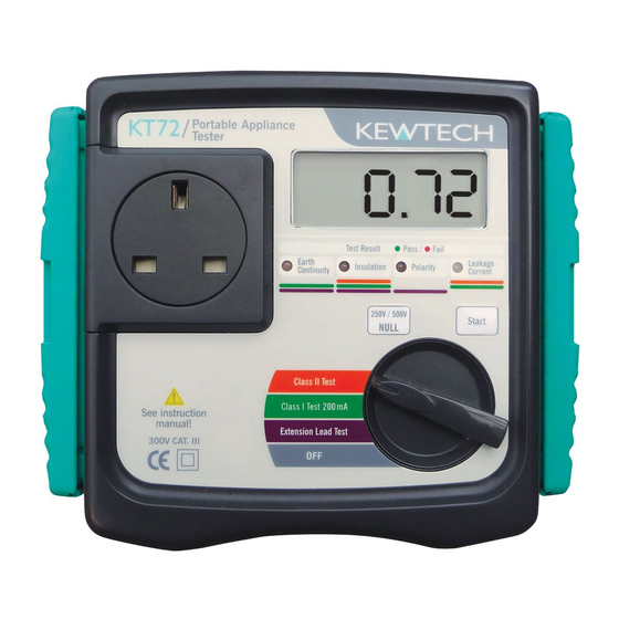
KT72
PAT TESTER WITH AUTO
TEST SEQUENCES
•
Performs Earth bond at 200mA at both +ve and -ve
polarities (IT appliance safe)
•
250V / 500V insulation test voltages
•
Substitute leakage tests
•
Single rotary dial position initiates test sequence
•
Class I IT 200mA Earth Bond
•
Class II
•
Extension lead test – including polarity
•
LED indication of pass / fail as well as a result display
•
Automatic check if appliance is switched on or not
•
Test 110V appliances for earth bond and insulation
(with appropriate test adaptor).
•
Tests in accordance with the IEE Code of Practice
•
Powered by batteries
ACCESSORIES
•
Earth lead
•
Instruction Manual
•
Calibration Certificate
•
Extension Lead Adaptor
OPTIONAL
•
Pass & Fail labels
•
PATLOG1 PAT record log book for multiple sites
•
PATLOG2 for single sites, including pass labels
t: 01494 792 212
KT72
PAT Tester with
Auto Test Sequence
MEASUREMENT OF PROTECTIVE CONDUCTOR RESISTANCE - R
Test function
Measuring range
Resolution
Open-circuit voltage
Measuring current
Accuracy
MEASUREMENT OF INSULATION RESISTANCE - R
Rating
Measuring range
Resolution
Rated voltage
Short-circuit current
Accuracy
SUSTITUTE LEAKAGE CURRENT
Test function
Measuring range
Resolution
Accuracy
LED Colour
Extension Lead
Class I
Class II
kewtechcorp.com
IT 200mA continuity test
0 - 19.99 Ω
10mΩ
200mA DC (nominal)
±(3%rdg ± 5dgt)
250V / 20M Ω and 500V / 20M Ω
0.1~19.99M Ω
250V/500V DC(-0%/+30%) @250k
2.5mA DC or less
± (2%rdg+3dgt)
Leakage current test
0.1-12.00A rms
0.01mA
±(3%rdg ± 5dgt)
Protective conductor
Insulation
resistance
resistance
Green
Amber
Green
Rpe < 0.1 Ω
Ppe < 0.1 Ω
Rins > 1M Ω
< 0.3 Ω
Rpe < 0.1 Ω
Ppe < 0.1 Ω
Rins > 1M Ω
< 0.3 Ω
Rins > 2M Ω
e: sales@kewtechcorp.com
PE
5V
INS
10kΩ
Ω/500kΩ
Substitute
Polarity
Leakage
current
Green
Green
Cont < 10 Ω
Leak < 0.75mA
Leak < 0.25mA
Advertisement
Table of Contents

Subscribe to Our Youtube Channel
Related Manuals for Kewtech KT72


Summary of Contents for Kewtech KT72
- Page 1 KT72 PAT Tester with Auto Test Sequence PRODUCT DATA SHEET KT72 PAT TESTER WITH AUTO TEST SEQUENCES • Performs Earth bond at 200mA at both +ve and -ve polarities (IT appliance safe) • 250V / 500V insulation test voltages •...
- Page 2 This instrument must only be used by a competent and trained person and operated in strict accordance with these instructions. KEWTECH will not accept liability for any damage or injury caused by misuse or non-compliance with the instructions or with the safety procedures.
- Page 3 Safe testing # DANGER ● Since a high voltage of 250V or 500V is being output continuously, when measuring insulation resistance, the user may get an electrical shock. Any capacitors in the appliance under test may become charged during testing and may contain hazardous voltages do not touch them.
- Page 4 The KT72 has a dedicated cover to protect against an impact from the 2. Procedure of removing outside and to prevent the fascia, the LCD, and the connector socket from cover becoming dirty. The cover can be detached and put on the backside of the main body during measurement.
- Page 5 3. Product 3.1 Product summary summary and The KT72 is a hand-held battery powered portable appliance tester, explanation performing three functions to ensure the Safety of Class I and Class II appliances. Readings are displayed on a large liquid crystal display...
- Page 6 3.2 Test Functions Product summary and KT72 has the following features. explanation Function Tests of contents ● Protective conductor resistance (Test current 200mA DC nominal) Class I Test 200mA ● Insulation (Test voltage 250V DC or 500V ● Substitute leakage current test ●...
- Page 7 Product 3.4 Instrument layout summary and Front View explanation (1) Test socket (2) LCD (3) LEDs for test result (4) Start switch (5) NULL /250V-500V switch (6) Function switch End View (7) Terminal for Extension lead adaptor (8) Terminal for RPE – Test lead Fig.3 ⑴...
- Page 8 ⑸ NULL/250V-500V switch Product summary and ● The rotary dial has to be set to a Class l or Extension Lead test for explanation this button to be used to zero out the test lead resistance. ● The rotary dial has to be set to Class ll for this button to be used to select either 250 V or 500V insulation test voltage ⑹...
- Page 9 Product 3.5 Explanation for indications summary and LCD Display explanation Appears when the batteries are RPE Continuity indication (with both polarities) becoming low Leakage current indication Null indication Unit indication Over range display: “ >” is displayed on the LCD. Insulation measurement voltage Fig.7...
- Page 10 List of display message Product summary and Displayed when the value at preliminary explanation measurement for the protective conductor r e s i s t a n c e e x c e e d s 2 0 Ω , a n d t h e measurement cannot be carried out.
- Page 11 4.Specification 4.1 General specification, measuring range and accuracy Measurement of earth continuity (protective conductor resistance) - RPE Test function 200mA continuity 0 ~ 19.99Ω Measuring range (including pre-set Null values) (*2) Resolution 10mΩ Open-circuit voltage 5V DC Measuring current 200mA DC (nominal) Accuracy ±...
- Page 12 table.1: Summary of flexible table resistance rounded to two decimal places* Specification Nominal Conductor csa Resistance Max. carrying – should be marked on Length (at 20° ) current flexible cable (Ω) 0.04 0.08 0.12 0.16 0.025 0.05 0.75 0.08 0.10 0.13 0.02 0.04...
- Page 13 Specification 4.3 Reference test condition Unless otherwise specified, this specification is dependent on the following conditions. ⑴ Ambient temperature: 23±5˚C ⑵ Relative humidity: 45 ~ 75% ⑶ Attitude: Horizontal ⑷ Altitude: 2000m or less Operating temperature and humidity range 0ºC ~ +40ºC Relative humidity: 85% or less (no condensation) Storage temperature and humidity range -20ºC ~ +60ºC Relative humidity: 85% or less (no condensation) Power supply...
- Page 14 0.1Ω, which is a low value. So even the resistance of Test Leads will affect the measurement result. The KT72 can cancel the resistance of the test lead by pressing the NULL | 250V/500V switch. The procedure of Null setting is shown below.
- Page 15 Preparation 5.3.1 Null setting for Class I Test before a ⑴ Set the function switch to Class l Test 200mA function. measurement ⑵ Insert the Earth pin adapter (M-8251) in to the end of the Earth terminal of the Test socket. ⑶...
- Page 16 5.3.2 Null setting for Extension Lead Test Preparation before a ⑴ Set the function switch to Extension Lead Test function. measurement ⑵ Connect the Extension lead adaptor KAMP S (UK) as indicated in Fig.10, and then follow the procedure described at clause 5.3.1 (4). ⑶...
- Page 17 6. Measuring 6.1 Class I Test (200mA earth bond test) method The purpose of the test carried out for Class I appliances is to check the resistance of earth continuity from exposed metal parts and the plug is below a certain level and the insulation resistance between live and neutral connected together and earth is above 1MΩ.
- Page 18 Measuring Class I Test Flowchart method Start Check earth connections and press start again. (1). Preliminary measurement Lights up in red (*4) RPE≦20Ω? “no”→“Con” is displayed alternately on the LCD. (2). Protective conductor resistance. (*5) RPE≦0.1Ω? Lights up in red RPE<...
- Page 19 Measuring Note method ● (*4) This instrument conducts a Preliminary measurement before conducting Protective conductor resistance measurement. In case that the resistance value exceeds 20Ω, “no” and “Con” are alternately displayed on the LCD, and the next measurement in the sequence will not be conducted.
- Page 20 6.2 Class ll Test Measuring method The Class ll appliances have the indication of “DOUBLE INSULATION” or the symbol. The class ll insulation test is to check the insulation resistance and leakage current of the appliances is within the range defined in the standards.
- Page 21 Measuring Class Il Test Flowchart method Start When the resistance (*7) (1). Appliance switch test between L-N is about 100kΩ or more “ oFF”→“ ? ” is displayed Is the appliance alternately on the LCD. switched on? (*6) Re-start (2). Insulation resistance between L/N and PE. LnE ≧2MΩ? Lights up in red “no”→“LnE”→“value”...
- Page 22 Measuring method Note ● (*6)This instrument has a Re-Start function. It can proceed to the next step by pressing the Start switch again even if the result was a fail. ● (*7) When conducting Insulation resistance test and Leakage current test, the appliance under test must be being switched ON.
- Page 23 Measuring 6.3 Extension Leads Test method This test is for extension leads, and checks for; ● Protective conductor resistance. ● Insulation resistance between L/N and PE. ● Short test between L and N. ● Polarity check of the Line and Neutral terminals of the plug and socket.
- Page 24 Measuring Extension Leads Test Flowchart method Start Check earth connections and press start again (1). Preliminary measurement Lights up in red (*4) RPE≦20Ω? “no”→“Con” is displayed alternately on the LCD. (2). Protective conductor resistance test. (*5) RPE≦0.1Ω? Lights up in red RPE<...
- Page 25 Measuring Note method ● (*4) This instrument conducts a Preliminary measurement before conducting the Protective conductor resistance measurement. In the case that the resistance value exceeds 20Ω, “no” and “Con” are alternately displayed on the LCD, and the next measurement in the sequence will not be conducted.
- Page 26 7. Battery # DANGER and Fuse ● N e v e r a t t e m p t t o r e p l a c e b a t t e r i e s w h i l e m a k i n g Replacement measurements.
- Page 27 Battery and Fuse Replacement Spare Fuse Screw Fuse Battery Fig.15...
- Page 28 The strap and test lead case can be attached to the instrument as 8. Case and strap below. assembly Pass the strap belt down through the side panel of the main body from the top, and up through the slots of the test lead case from the bottom. (Fig.
Need help?
Do you have a question about the KT72 and is the answer not in the manual?
Questions and answers