Table of Contents
Advertisement
Quick Links
Operating instructions
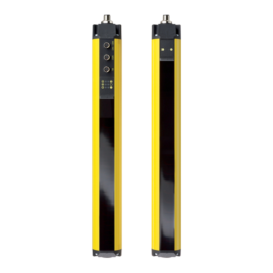
Safety light curtain
Operating instructions. . . . . . . . . . . .pages 1 to 20
EN
Translation of the original operating instructions
Vous trouverez la version
FR
actuelle du mode d'emploi dans
votre langue nationale officielle
sur l'Internet,
www.schmersal.net.
U vindt de huidige versie van de
NL
gebruikshandleiding in uw
officiële landstaal op het Inter-
net, www.schmersal.net.
EU公用語で書かれた最新の取扱
JP
説明書は,インターネッ
(www.schmersal.net) からダウ
ンロードできます。
Content
1
About this document
1.1
Function . . . . . . . . . . . . . . . . . . . . . . . . . . . . . . . . . . . . . . . . . . . .1
1.2
Target group: authorised qualiied personnel. . . . . . . . . . . . . . . .1
1.3
Explanation of the symbols used . . . . . . . . . . . . . . . . . . . . . . . . .1
1.4
Appropriate use . . . . . . . . . . . . . . . . . . . . . . . . . . . . . . . . . . . . . .1
1.5
General safety instructions . . . . . . . . . . . . . . . . . . . . . . . . . . . . .2
1.6
Warning about misuse . . . . . . . . . . . . . . . . . . . . . . . . . . . . . . . . .2
1.7
Exclusion of liability . . . . . . . . . . . . . . . . . . . . . . . . . . . . . . . . . . .2
2
2.1
Ordering code . . . . . . . . . . . . . . . . . . . . . . . . . . . . . . . . . . . . . . .2
2.2
Special versions. . . . . . . . . . . . . . . . . . . . . . . . . . . . . . . . . . . . . .2
2.3
Scope of delivery and accessories . . . . . . . . . . . . . . . . . . . . . . .2
2.3.1 Optional accessories . . . . . . . . . . . . . . . . . . . . . . . . . . . . . . . . . .2
2.4
Destination and use . . . . . . . . . . . . . . . . . . . . . . . . . . . . . . . . . . .2
2.5
Technical data . . . . . . . . . . . . . . . . . . . . . . . . . . . . . . . . . . . . . . .3
2.6
Response time (reaction time) . . . . . . . . . . . . . . . . . . . . . . . . . . .3
2.7
Safety classiication . . . . . . . . . . . . . . . . . . . . . . . . . . . . . . . . . . .4
2.8
Functions . . . . . . . . . . . . . . . . . . . . . . . . . . . . . . . . . . . . . . . . . . .4
2.8.1 Factory setting . . . . . . . . . . . . . . . . . . . . . . . . . . . . . . . . . . . . . . .4
2.8.2 Restart interlock (manual reset). . . . . . . . . . . . . . . . . . . . . . . . . .4
2.8.3 Contactor control (EDM) . . . . . . . . . . . . . . . . . . . . . . . . . . . . . . .4
2.8.4 Start interlock . . . . . . . . . . . . . . . . . . . . . . . . . . . . . . . . . . . . . . . .4
2.8.5 Beam coding . . . . . . . . . . . . . . . . . . . . . . . . . . . . . . . . . . . . . . . .4
2.8.6 Blanking . . . . . . . . . . . . . . . . . . . . . . . . . . . . . . . . . . . . . . . . . . . .5
2.8.7 Testing . . . . . . . . . . . . . . . . . . . . . . . . . . . . . . . . . . . . . . . . . . . . .6
2.9
Operating mode muting . . . . . . . . . . . . . . . . . . . . . . . . . . . . . . . .6
2.9.1 Muting sensors MS . . . . . . . . . . . . . . . . . . . . . . . . . . . . . . . . . . .6
2.9.2 Muting lamp . . . . . . . . . . . . . . . . . . . . . . . . . . . . . . . . . . . . . . . . .7
2.9.3 Signal sequence muting. . . . . . . . . . . . . . . . . . . . . . . . . . . . . . . .7
2.9.4 Coniguration of the muting function . . . . . . . . . . . . . . . . . . . . . .7
2.9.5 Saving the data . . . . . . . . . . . . . . . . . . . . . . . . . . . . . . . . . . . . . .9
2.9.6 Muting applications . . . . . . . . . . . . . . . . . . . . . . . . . . . . . . . . . . .9
2.10 Operating mode cyclic operation . . . . . . . . . . . . . . . . . . . . . . . .10
3
3.1
General conditions . . . . . . . . . . . . . . . . . . . . . . . . . . . . . . . . . . . 11
3.2
Protection ield and approach . . . . . . . . . . . . . . . . . . . . . . . . . . 11
3.3
Alignment . . . . . . . . . . . . . . . . . . . . . . . . . . . . . . . . . . . . . . . . . .12
3.4
Safety distance . . . . . . . . . . . . . . . . . . . . . . . . . . . . . . . . . . . . .12
3.4.1 Minimum distance to relecting surfaces . . . . . . . . . . . . . . . . . .13
3.5
Dimensions . . . . . . . . . . . . . . . . . . . . . . . . . . . . . . . . . . . . . . . .14
Encontrará el manual de
ES
instrucciones actual en su
idioma oficial de la UE en
nuestra página de Internet
www.schmersal.net.
Il manuale d'istruzioni aggior-
IT
nato nella vostra lingua (lingua
ufficiale UE) è scaricabile in
Internet all'indirizzo
www.schmersal.net.
4
4.1
Wiring example Muting . . . . . . . . . . . . . . . . . . . . . . . . . . . . . . .15
Transmitter & Cable - Muting Mode . . . . . . . . . . . . . . . . . . . . . .15
4.2
Wiring example Cyclic operation . . . . . . . . . . . . . . . . . . . . . . . .16
Emitter & Cable - Cyclic operation . . . . . . . . . . . . . . . . . . . . . . .16
4.3
Sensor connection ield . . . . . . . . . . . . . . . . . . . . . . . . . . . . . . .17
5
5.1
Check before start-up . . . . . . . . . . . . . . . . . . . . . . . . . . . . . . . .17
5.2
Maintenance . . . . . . . . . . . . . . . . . . . . . . . . . . . . . . . . . . . . . . .17
5.3
Regular check . . . . . . . . . . . . . . . . . . . . . . . . . . . . . . . . . . . . . .17
5.4
Half-yearly inspection. . . . . . . . . . . . . . . . . . . . . . . . . . . . . . . . .17
5.5
Cleaning. . . . . . . . . . . . . . . . . . . . . . . . . . . . . . . . . . . . . . . . . . .17
6
6.1
LED status information. . . . . . . . . . . . . . . . . . . . . . . . . . . . . . . .18
6.2
Fault diagnostic . . . . . . . . . . . . . . . . . . . . . . . . . . . . . . . . . . . . .19
6.3
Extended diagnostic. . . . . . . . . . . . . . . . . . . . . . . . . . . . . . . . . .19
7
7.1
Disassembly. . . . . . . . . . . . . . . . . . . . . . . . . . . . . . . . . . . . . . . .19
7.2
Disposal . . . . . . . . . . . . . . . . . . . . . . . . . . . . . . . . . . . . . . . . . . .19
8
8.1
Contact. . . . . . . . . . . . . . . . . . . . . . . . . . . . . . . . . . . . . . . . . . . .19
8.2
EC Declaration of conformity . . . . . . . . . . . . . . . . . . . . . . . . . . .20
1. About this document
1.1 Function
This operating instructions manual provides all the information you
need for the mounting, set-up and commissioning to ensure the safe
operation and disassembly of the safety switchgear. The operating inst-
ructions must be available in a legible condition and a complete version
in the vicinity of the device.
1.2 Target group: authorised qualified personnel
All operations described in this operating instructions manual must
be carried out by trained specialist personnel, authorised by the plant
operator only.
Please make sure that you have read and understood these operating
instructions and that you know all applicable legislations regarding
occupational safety and accident prevention prior to installation and
putting the component into operation.
The machine builder must carefully select the harmonised standards to
be complied with as well as other technical specifications for the selec-
tion, mounting and integration of the components.
1.3 Explanation of the symbols used
Information, hint, note:
This symbol is used for identifying useful additional information.
Caution: Failure to comply with this warning notice could
lead to failures or malfunctions.
Warning: Failure to comply with this warning notice could
lead to physical injury and/or damage to the machine.
1.4 Appropriate use
The products described in these operating instructions are developed to
execute safety-related functions as part of an entire plant or machine. It
is the responsibility of the manufacturer of a machine or plant to ensure
the correct functionality of the entire machinery or plant.
EN
SLC 425I
1
Advertisement
Table of Contents

Subscribe to Our Youtube Channel
Related Manuals for schmersal SLC 425I


Summary of Contents for schmersal SLC 425I
-
Page 1: Table Of Contents
Operating instructions Safety light curtain SLC 425I Electrical connection Wiring example Muting .......15 4.1.1 Connector coniguration Receiver,... -
Page 2: General Safety Instructions
2. Product description 2.4 Destination and use 2.1 Ordering code The SLC 425I is a non-contact, self-testing safety guard, which is used This operating instructions manual applies to the following types: for the protection of hazardous points, hazardous areas and machine accesses. -
Page 3: Technical Data
Operating instructions Safety light curtain SLC 425I 2.5 Technical data 2.6 Response time (reaction time) Standards: EN 61496-1; CLC/TS 61496-2; The response time of the safety light curtain SLC 425 I depends on the EN ISO 13849; EN 62061 hight of the protected field, the resolution, the number of light beams... -
Page 4: Safety Classiication
PC or laptop. 2.8.1 Factory setting 2.8.5 Beam coding The SLC 425I system features many functions without additional The beam coding of the safety light curtain must be adjusted, when devices. The following table gives an overview of the possible functions systems operating in each other's vicinity and a set-up as shown in the and the factory settings configuration. -
Page 5: Blanking
The first beam, which is located immediately behind the diagnostic window, cannot be blanked. The SLC 425I can blank one or more beams in the protection field. A combination of fixed and variable blanking is possible. This function allows for an interruption of the protection height without the outputs being disabled in case of material movement in the protec- tion field, e.g. -
Page 6: Testing
After connection and fitting by an expert, the following instructions must signal evaluation by the control system. be respected and observed: • Set-up of the sensors to the operating instructions SLC 425I. The mu- Installation of the muting sensors ting function must not be started by a person unintentionally accessing If 4 muting sensors are used, the switching outputs of the muting the hazardous area. -
Page 7: Muting Lamp
(direction detection 1). The material first actuates the proteciton field of the SLC 425I, after that MS 3 (first sensor group) and finally the MS The muting cycle time must take variations in the belt speed as well as 4 (second sensor group). - Page 8 Reduced muting cycle Override A normal muting cycle is terminated by a muting sensor in the following This function enables bridging the outputs of the SLC 425I in case of way: failure (voltage interruption, material jamming). The function is limited in •...
-
Page 9: Saving The Data
The minimum signal length between the sensors, which are fitted additional button closest to the SLC 425I, must be at least 50 ms. This corresponds to a "Confirm within 10 seconds by clicking this button" minimum distance of 100 mm at a belt speed of 2.0 m/s. -
Page 10: Operating Mode Cyclic Operation
MS to the transported material. Operating principle cyclic operation The distance of MS 1 and MS 2 to the protection field of the SLC 425I The interventions of the operator (N) (1) in the protection field during must be chosen as small as possible as well. -
Page 11: Mounting
Machine contact The machine contact is a signal, which is transmitted from the machine control to the SLC 425I. This contact is used for the cycle reset and enables an immediate intervention in the protection field. The signal is integrated in the control system of the SLC 425I with the status informa-... -
Page 12: Alignment
(entire safety guard) • Approach speed • Resolution of the safety light curtain Safety light curtain SLC 425I The safety distance for resolutions 14 mm up to 40 mm is calculated by means of the following formula: (1) S = 2000 mm/s * T + 8 (d - 14) [mm]... -
Page 13: Minimum Distance To Relecting Surfaces
Operating instructions Safety light curtain SLC 425I Distance between transmitter and receiver Minimum distance Safety distance to the hazardous area a [mm] Safety distance (S) 0.2 … 3.0 Limit of the hazardous point Tool - upper part Signal to stop the... -
Page 14: Dimensions
SLC 425I-E/R0730-XX-RFBC 730 SLC 425I-E/R0810-XX-RFBC 810 1028 SLC 425I-E/R0890-XX-RFBC 890 1008 1072 1044 1108 SLC 425I-E/R0970-XX-RFBC 970 1088 1152 1124 1188 SLC 425I-E/R1050-XX-RFBC 1050 1168 1232 1204 1268 SLC 425I-E/R1130-XX-RFBC 1130 1248 1312 1284 1348 SLC 425I-E/R1210-XX-RFBC 1210 1328 1392 1364 1428... -
Page 15: Electrical Connection
Operating instructions Safety light curtain SLC 425I 4. Electrical connection 4.1 Wiring example Muting + 24VDC Sensor connec- tion: MS 1 MS 2 - with 2 muting sensors MS 1 MS 2 Bridge 1 Brücke 1 - with 4 + 24VDC... -
Page 16: Wiring Example Cyclic Operation
Operating instructions Safety light curtain SLC 425I 4.2 Wiring example Cyclic operation Kn 1 Kn 2 Earth connection Erdung Legend Cable: Connector Bridge 1: Restart interlock (manual reset) active female M12 / 8 pole (The cable bridge between Pin 5 and 6 must always... -
Page 17: Sensor Connection Ield
For safety reasons, all inspection results must be archived. The opera- Muting sensor 1/machine contact MC, muting sensor 2, muting lamp ting principle of the SLC 425I and the machine must be known in order to be able conducting an inspection. If the fitter, the planning technician... -
Page 18: Diagnostic
Operating instructions Safety light curtain SLC 425I 6. Diagnostic Receiver Status LED Description 6.1 LED status information OSSD ON Protection field clear Flashing Diagnostic mode active Receiver OSSD OFF Protection field interrupted, sys- tem or configuration error Multifunction Restart Blanking... -
Page 19: Fault Diagnostic
Tel:+49 (0) 202 64 74 -0 Fax:+49 (0) 202 64 74- 100 You will also find detailed information regarding our product variety on our website: www. schmersal.com Repair handling / shipping: Safety Control GmbH Am Industriepark 11 D-84453 Mühldorf / Inn... -
Page 20: Ec Declaration Of Conformity
Christian Spranger Klaus Schuster Managing Director Managing Director The currently valid declaration of conformity can be down- loaded from the internet at www.schmersal.net. Safety Control GmbH Am Industriepark 33 D-84453 Mühldorf / Inn Telefon +49 - (0)86 31 - 187 - 9 60...
Need help?
Do you have a question about the SLC 425I and is the answer not in the manual?
Questions and answers