Tektronix DSA8300 Quick Start User Manual
Digital serial analyzer
Hide thumbs
Also See for DSA8300:
- Programmer's manual (455 pages) ,
- Technical reference (277 pages) ,
- Service manual (138 pages)

Subscribe to Our Youtube Channel
Related Manuals for Tektronix DSA8300


Summary of Contents for Tektronix DSA8300
- Page 1 DSA8300 Digital Serial Analyzer Quick Start User Manual *P071289701* 071-2897-01...
- Page 3 DSA8300 Digital Serial Analyzer Quick Start User Manual Revision A www.tektronix.com 071-2897-01...
- Page 4 Copyright © Tektronix. All rights reserved. Licensed software products are owned by Tektronix or its subsidiaries or suppliers, and are protected by national copyright laws and international treaty provisions. Tektronix products are covered by U.S. and foreign patents, issued and pending. Information in this publication supersedes that in all previously published material.
- Page 5 Warranty Tektronix warrants that this product will be free from defects in materials and workmanship for a period of one (1) year from the date of shipment. If any such product proves defective during this warranty period, Tektronix, at its option, either will repair the defective product without charge for parts and labor, or will provide a replacement in exchange for the defective product.
-
Page 7: Table Of Contents
Setting Pattern Sync and FrameScan Controls................DSA8300 Quick Start User Manual... - Page 8 Restoring the Operating System with Restore Media ............... .. Index DSA8300 Quick Start User Manual...
-
Page 9: General Safety Summary
Do not operate in wet/damp conditions. Do not operate in an explosive atmosphere. Keep product surfaces clean and dry. Provide proper ventilation. Refer to the manual's installation instructions for details on installing the product so it has proper ventilation. DSA8300 Quick Start User Manual... - Page 10 DANGER indicates an injury hazard immediately accessible as you read the marking. WARNING indicates an injury hazard not immediately accessible as you read the marking. CAUTION indicates a hazard to property including the product. The following symbol(s) may appear on the product: DSA8300 Quick Start User Manual...
-
Page 11: Compliance Information
For example, if an 80C01–CR operating in clock-recovery trigger mode exhibits 3.5 ps RMS of edge jitter, with no EMC field applied and for an ideal jitterless input, then for applied fields up to 3 V/m the edge jitter, degradation would typically result in a total RMS jitter of: DSA8300 Quick Start User Manual... - Page 12 Complies with the EMC provision of the Radiocommunications Act per the following standard, in accordance with ACMA: CISPR 11:2003. Radiated and Conducted Emissions, Group 1, Class A, in accordance with EN 61326-1:2006 and EN 61326-2-1:2006. DSA8300 Quick Start User Manual...
-
Page 13: Safety Compliance
These are sheltered locations where neither temperature nor humidity is controlled. The area is protected from direct sunshine, rain, or direct wind. Pollution Degree 4. Pollution that generates persistent conductivity through conductive dust, rain, or snow. Typical outdoor locations. DSA8300 Quick Start User Manual... - Page 14 Measurement Category II. For measurements performed on circuits directly connected to the low-voltage installation. Measurement Category I. For measurements performed on circuits not directly connected to MAINS. Overvoltage Category Overvoltage Category II (as defined in IEC 61010-1) viii DSA8300 Quick Start User Manual...
-
Page 15: Environmental Considerations
This symbol indicates that this product complies with the applicable European Union requirements according to Directives 2002/96/EC and 2006/66/EC on waste electrical and electronic equipment (WEEE) and batteries. For information about recycling options, check the Support/Service section of the Tektronix Web site (www.tektronix.com). -
Page 16: Preface
Preface Preface Documentation This manual describes the installation and operation of the DSA8300 Digital Serial Analyzer including basic operation and concepts. For more detailed information, see the online help on your instrument. NOTE. The screen images in this manual may differ slightly from other versions of product software. -
Page 17: Key Features
Key Features Key Features The DSA8300 is a state-of-the-art equivalent time sampling oscilloscope that provides the highest fidelity measurement and analysis capabilities for communications signal analysis, serial data network analysis, and serial data link analysis applications. Highest Fidelity Signal Capture... - Page 18 Complete suite of over 120 automated measurements for NRZ, RZ, and Pulse signal types Automated mask testing with over 80 industry-standard masks. New masks can be imported into the DSA8300 to support new emerging standards. In addition, users can define their own masks for automated mask testing...
-
Page 19: Install Your Instrument
Install Your Instrument Unpack the instrument and check that you received all items listed as Standard Accessories. Recommended accessories and probes, instrument options, and upgrades are listed in the online help. Check the Tektronix Web site (www.tektronix.com) for the most current information. -
Page 20: Operating Considerations
Install Your Instrument Operating Considerations The following information lists the specifications related to the operation of the mainframe. Refer to the DSA8300 Digital Serial Analyzer Specifications and Performance Verification Manual for a complete list of specifications. Mechanical Clearance requirements Dimensions... - Page 21 ±1.5 V (DC + peak AC) maximum input voltage Trigger Prescaled Input absolute maximum ±1.1 V input (typical) External 10 MHz Reference Input 500 mV to 5 V AC coupled into 1 kΩ, ±5 V maximum DSA8300 Quick Start User Manual...
-
Page 22: Installing Modules
Six channels: Two large modules and two small modules Seven channels: One large module, installed in CH3 compartment, and three small modules Seven channels: One large module, installed in CH1 compartment, and three small modules DSA8300 Quick Start User Manual... -
Page 23: Module Configuration
TekScope software versions earlier than 6.1.X, always power off the mainframe to remove or install modules. Failure to do so may result in damage to the module or mainframe. Download the latest DSA8300 software from www.tek.com/software. 1. Select Utilities > View/Change Module Config to open the module configuration... -
Page 24: Powering The Instrument On And Off
2. Toggle the mains switch to on. 3. Use the front panel power button to switch the instrument on and off. CAUTION. To prevent damaging the modules, do not install or remove any modules while the instrument is powered on. DSA8300 Quick Start User Manual... -
Page 25: Adding A Second Monitor
Use a DVI-I to SVGA adapter (not supplied) to connect to SVGA monitors. 3. Power on the instrument. 4. Power on the external monitor. The instrument detects the external monitor and displays the contents of the instrument screen. DSA8300 Quick Start User Manual... - Page 26 7. If using an extended desktop, click the external monitor 2 box in the Position pane and drag the monitor to the position that relates to the physical position of monitor 2 in relation to monitor 1. DSA8300 Quick Start User Manual...
- Page 27 If the new settings are correct, click OK. You have about 15 seconds before the instrument automatically returns to the previous display settings. 10. Click OK to close the Intel Graphics Media Accelerator Driver window. DSA8300 Quick Start User Manual...
-
Page 28: Getting Acquainted With Your Instrument
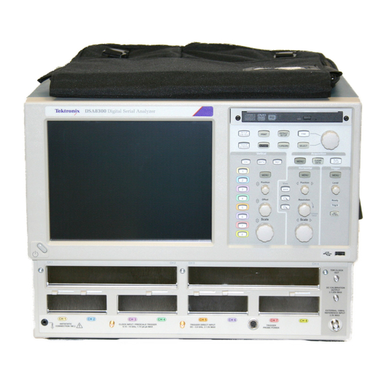
3. Clock Input/Prescale Trigger input. 4. Trigger direct input. 5. Trigger probe power. 6. External 10 MHz reference input. 7. DC calibration output. 8. TDR Clock Out signal. 9. USB port(s). 10. Control panel. 11. DVD-ROM/CD-RW drive. DSA8300 Quick Start User Manual... -
Page 29: Control Panel
12. Push a channel button to select and display a waveform for that channel. A lit button indicates selected and displayed waveforms for that channel. An unlit button indicates that the channel is not selected. DSA8300 Quick Start User Manual... -
Page 30: Rear Panel
Refer to the Programmer Manual installed on the instrument. 3. Computer I/O panel. (See page 15, Computer I/O Panel.) 4. AC input. 5. Fuses. 6. Mains power switch. DSA8300 Quick Start User Manual... -
Page 31: Computer I/O Panel
Getting Acquainted with Your Instrument Computer I/O Panel 1. Audio line out 2. Mic input 3. USB ports 4. DVI-I video out for dual-monitor display 5. COM1 6. PS2 (keyboard) 7. PS2 (mouse) 8. COM2 9. LAN DSA8300 Quick Start User Manual... -
Page 32: The User Interface
10. Controls Bar. Click to select a waveform (channel, math, or reference), as well as quick access to scale, offset, and position controls for adjustment. 11. Display. Contains live, reference, and math waveforms, and histograms, cursors and test masks when enabled. DSA8300 Quick Start User Manual... -
Page 33: Display - Single Waveform View
4. Right-click on a waveform or its icon to open the context menu with setup controls and properties. 5. Drag ground reference icon to add offset to a waveform. 6. Drag across the waveform area to horizontally zoom the boxed waveform segment to full screen width. DSA8300 Quick Start User Manual... -
Page 34: Display - Magnified Waveform Views
4. Drag the markers to enclose the portion of waveform to appear in Mag1 View. 5. Drag the markers to enclose the portion of waveform to appear in Mag2 View. 6. Drag the border between graticules to vertically size Main, Mag1, and Mag2 Views. DSA8300 Quick Start User Manual... -
Page 35: Accessing Online Help
For in-depth, contextual overviews, most dialog boxes have a Help button. Click the button to open the help system for information on that dialog box. Select Help > Help Contents and Index to open the overall help system. DSA8300 Quick Start User Manual... -
Page 36: Inspect Your Instrument
Inspect Your Instrument Use the following procedure to verify the functionality of your instrument. For a complete performance verification, see the DSA8300 Digital Serial Analyzer Performance Verification and Specifications Manual, which can be downloaded from the Tektronix Web site. Verify Internal Diagnostics Pass 1. - Page 37 6. Verify that the Loop and Halt on Failure boxes are unchecked. 7. Click Run. 8. Verify that all tests display Pass in the Status column when the diagnostics complete. If diagnostic failures occur, contact your local Tektronix service center. DSA8300 Quick Start User Manual...
-
Page 38: Optimizing Measurement Accuracy
Failure to install the 50 Ω terminations on electrical inputs can cause erroneous compensation failures or results. 3. If you powered off the instrument to change module configuration, power on the instrument and wait 20 minutes for the warm-up period. DSA8300 Quick Start User Manual... - Page 39 9. Click Execute. Follow the on-screen instructions regarding signal and trigger inputs and terminations; be sure to follow electrostatic handling precautions (see the user information for your sampling module) when following these instructions. DSA8300 Quick Start User Manual...
- Page 40 Green means that all modules have been successfully compensated. Yellow means that the instrument has not competed its 20 minute warm-up period. Red means that one or more modules require compensation. DSA8300 Quick Start User Manual...
-
Page 41: Dark-Level And User Wavelength Gain Compensations
User Wavelength Gain compensation optimizes an optical channel for your custom input signal. 1. Install one or two optical sampling modules in the instrument. Set the acquisition system to run continuously. 2. Select the channel to compensate. 3. Select Setup > Vertical. DSA8300 Quick Start User Manual... - Page 42 Vert Setup dialog box. 7. Enter the wavelength and measured power of the signal applied to the channel In the User Wavelength Gain Compensation dialog box. 8. Click OK to execute the compensation. DSA8300 Quick Start User Manual...
-
Page 43: Acquisition
See the user manual for the installed sampling module for connection requirements. CAUTION. Discharge electrical cables to ground before connecting them to a module. 2. Connect an appropriate trigger signal to the instrument. (See page 36, Triggers.) DSA8300 Quick Start User Manual... - Page 44 If no reference waveforms are loaded into the channels, the Recall Waveform dialog box appears. 4. Use the Vertical Position, Offset, and Scale knobs to adjust the vertical parameters of the selected waveform. DSA8300 Quick Start User Manual...
-
Page 45: Using Factory Default Setup
Push Set to 50% in the Trigger controls, if required, to stabilize the display when using the Trigger Direct Input connector. Using Factory Default Setup 1. To quickly return to the factory default settings, push DEFAULT SETUP. 2. Click Yes to restore the settings. DSA8300 Quick Start User Manual... -
Page 46: Using Autoset
If the instrument does not autoset to your signal, select Setup > Horizontal, click the Comm Standard button, and select the signal type. Then push the Autoset button again. Select Utilities > Define Autoset to change the Autoset properties. DSA8300 Quick Start User Manual... -
Page 47: Accessing The Setup Dialog Boxes
1. Access the Setup dialog boxes by using the front panel buttons, the Setup menu item, or the Setup button. 2. Click on the tabs to select among the setup dialog boxes. DSA8300 Quick Start User Manual... -
Page 48: Changing The Acquisition Mode
If Stop After is set to Condition, pressing RUN/STOP causes only one acquisition to run if the original condition has been met. You need to push CLEAR DATA so that the condition must be met again. DSA8300 Quick Start User Manual... -
Page 49: Waveform Databases
10. Select one of the four grading methods. 11. If you selected one of the two Emphasized grading methods, slide the Emphasize Counts percentage control to specify the range of counts you want emphasized. DSA8300 Quick Start User Manual... -
Page 50: Setting The Display Style
3. Variable Persistence makes data persist for a specified time. New waveform displays accumulate data as new waveform records acquire, but with continuous replacement of the oldest data. Set a time at which the oldest data is removed. DSA8300 Quick Start User Manual... - Page 51 4. Use the Graticule settings to select the graticule style and the graticule color and screen background. DSA8300 Quick Start User Manual...
-
Page 52: Triggers
An internal clock for Free Run acquisition of signals. (Since the acquired signals are not synchronous with the trigger, this trigger source is useful primarily for locating a signal or clock and applying the appropriate offset to the data or trigger for proper synchronous waveform acquisition.) DSA8300 Quick Start User Manual... - Page 53 Internal Clock Recovery Data (NRZ) Mask Clock Trigger Mode: Other and Parametric Testing (w/ clock modulation effects – SSC) Clock Signal Trigger Source: Clock Input/Prescale Trigger input or Analysis Internal Clock Recovery Clock Trigger Mode: Eye DSA8300 Quick Start User Manual...
- Page 54 Triggers Table 1: Application-based trigger modes (cont.) Application Waveform display Trigger Source/Mode TDR/TDT and Trigger Source: TDR S-Parameter Analysis Low Repetition Trigger Source: External Direct Trigger input Rate Signals DSA8300 Quick Start User Manual...
-
Page 55: Setting Trigger Controls
Selecting a Clock Recovery trigger source requires that a module with clock recovery is available. Select the clock recovery standard from the pulldown lists or user-specified range controls. Selecting TDR as the trigger source uses the clock frequency setting in the Rate control. DSA8300 Quick Start User Manual... -
Page 56: Setting Pattern Sync And Framescan Controls
5. Enable FrameScan to automatically scan through a pattern (or part of a pattern). This FrameScan control is the same as the FrameScan control in the Horizontal Setup dialog box (changing either one affects the other). DSA8300 Quick Start User Manual... -
Page 57: Checking Trigger Status
You can check the status of the trigger from the front panel and in the application status bar. The status bar also displays the waveform count. 1. Check the READY and TRIG'D front-panel controls to determine the trigger status, or look at the trigger status in the application. DSA8300 Quick Start User Manual... -
Page 58: Waveform Measurements
3. Click on a measurement button in the Measurement tool bar. The instrument displays the most frequently used measurements for the selected waveform type and category. You can also access all of the measurement types from the MEAS setup dialog box. DSA8300 Quick Start User Manual... - Page 59 9. Note the portion of the waveform being measured. 10. Note the reference levels for the measurement. DSA8300 Quick Start User Manual...
- Page 60 15. Click the On box to turn gating on and to display the gates on screen. 16. Use the G1 (Gate1) and G2 spin controls to adjust the gates on screen such that the area to measure is between the gates. DSA8300 Quick Start User Manual...
- Page 61 Gate values are entered as a percentage of the waveform, displayed from left to right. If no keyboard is installed, access the virtual keyboard and use the touch screen to enter values. You can select and drag the gates to new locations by using a mouse or the touch screen. DSA8300 Quick Start User Manual...
-
Page 62: Turning Off Automatic Measurements
6. Note that measurement slot 3 is now labeled Not Defined and no measurement icon is displayed. 7. Note that measurement slot 1 has a measurement assigned. It is set to not display, but the measurement slot is still used. DSA8300 Quick Start User Manual... -
Page 63: Cursor Measurements
3. Push the SELECT button to toggle selection between the two cursors. The active cursor is represented by a solid line. 4. Turn the General Purpose knob to position each cursor on the waveform to measure the feature that interests you. DSA8300 Quick Start User Manual... - Page 64 7. Waveform cursors measure vertical and horizontal parameters simultaneously. Waveform cursors are attached to the waveform and track with the waveform points. 8. Read cursor measurement results in the readouts area of the display. DSA8300 Quick Start User Manual...
- Page 65 Magnify each point of interest in a separate time base, and then place one cursor on each point. The Δ-time cursor readout will then reflect the position and resolution of the magnified time bases. DSA8300 Quick Start User Manual...
-
Page 66: Math Waveforms
Elements that appear grayed out cannot be selected because they would result in an illegal entry. 4. Use the filter control in the dialog box to specify the rise time of any filters in the math waveform definition. DSA8300 Quick Start User Manual... -
Page 67: Display A Communication Signal
(Data signal to the module input, clock signal to the CLOCK INPUT/PRESCALER TRIGGER connector). CAUTION. Always observe optical cable and static-safe procedures and cautions as outlined in your sampling-module user manual when connecting cables to modules. DSA8300 Quick Start User Manual... - Page 68 3. Select the input signal source (1–8). 4. Select Setup > Horizontal and enter the communications standard or set the bit rate of the signal. 5. Push the AUTOSET front panel button. The instrument analyses and displays the signal. DSA8300 Quick Start User Manual...
-
Page 69: Mask Testing
filter. Then click the Mask tab to return to the mask settings. To autoset the waveform to the mask: 6. Click the Autoset Data button to perform a manual autoset on the mask-source waveform. DSA8300 Quick Start User Manual... - Page 70 Total Hits and set a count, such as 1, in the count box. These settings stop acquisition when mask violations satisfy the criteria you set. 11. Push the RUN/STOP button to restart acquisition, if stopped. DSA8300 Quick Start User Manual...
- Page 71 DATA button, followed by the RUN/STOP front-panel button. 15. Read the mask-hits count and margin percent (if enabled) in the readout. 16. You can use Mask Margins to explore design margins of your communications signal. DSA8300 Quick Start User Manual...
- Page 72 20. Assign each waveform to a waveform database, and acquire an adequate number of waveforms. 21. Stop signal acquisition (press the RUN/STOP button or use the Automatic Stop After condition). DSA8300 Quick Start User Manual...
- Page 73 (and only one) additional waveform. The Clear Data button resets all mask counts. In addition, if the source for mask testing is a waveform database, clicking this button clears the waveform database. DSA8300 Quick Start User Manual...
-
Page 74: Framescan
FrameScan mode superior to traditional methods. 1. Select the Horizontal Setup tab. 2. Click Pattern Sync/FrameScan Setup. 3. Click Enabled in FrameScan. 4. Set the Scan Bits to the number of bits or subframes to acquire. DSA8300 Quick Start User Manual... -
Page 75: To Use Tdr
(TDR module with single channel adjustment) for deskew adjustment. 7. Set the Deskew percent value. 8. Click Advanced TDR Setup to set the TDR step rate, reference source, and enable or disable incident waveform display. DSA8300 Quick Start User Manual... - Page 76 For a TDR module with single channel deskew capability, only the even-numbered channel of the module is selectable for deskew. For a TDR module with dual channel deskew capability, both channels of the module are selectable for deskew. (See page 66, Skew and Deskewing.) DSA8300 Quick Start User Manual...
-
Page 77: Phase Reference
NOTE. To use the phase reference function, you must have a phase reference module (such as the Tektronix 82A04), and a phase reference clock signal that is synchronous to the data to be acquired and connected to the phase reference module. - Page 78 Spread Spectrum Clocking (SSC): Enable SSC support when you want to acquire waveforms that are phase corrected and acquired relative to a trigger event that is using a Spread Spectrum Clocking signal. Sampling is still random around the trigger event. DSA8300 Quick Start User Manual...
-
Page 79: Histograms
2. Check the Enable Histogram box. 3. Click the Source button to select the waveform source. 4. Select a vertical or horizontal histogram. 5. Use the Display Options to change the appearance of the histogram. DSA8300 Quick Start User Manual... -
Page 80: Document Your Results
1. To Save a setup or a waveform, click Save Setup or Save Waveform in the File menu. 2. To export waveform data, click Export Waveform in the File menu. DSA8300 Quick Start User Manual... - Page 81 4. To copy a screen image into another application, choose the Print to file option in the print dialog box. Save the screen image in a format that is compatible with your application, and then insert the screen image into your document. DSA8300 Quick Start User Manual...
-
Page 82: Skew And Deskewing
Measure and match your cables. TDR modules such as 80E10, 80E08, and 80E04 allow you to measure cable delays with very high precision. In differential systems, use differential probes or differential SMA to single-ended active convertors, such as the Tektronix P7380SMA. -
Page 83: Methods To Adjust Skew
Using a Phase Adjuster Skew can be adjusted with the use of a variable delay line (phase adjuster). Tektronix part number 015-0708-00 is a phase adjuster with a 25 ps range and VSWR of 1.3:1 at 18 GHz. The advantage of a phase adjuster is that it is functionally invisible. -
Page 84: Setup Considerations And Procedures
80A05 connected during the deskew procedure. This ensures that any skew introduced by the 80A05 or the connecting cables are accounted for by the deskew procedure. Figure 1: Schematic diagram of reference planes in relation to signal DSA8300 Quick Start User Manual... - Page 85 ACQ On box for the source channel. This channel does not need to be displayed. 4. Connect a cable or TDR probe to the source channel to use for injecting the TDR step signal into the reference plane. DSA8300 Quick Start User Manual...
- Page 86 TDR CLOCK OUT connector to reduce the amplitude to an acceptable amplitude for the module. For fixture or DUT locations that do not support a cable attachment, the acquisition deskew signal can be injected by a P8018 single-ended TDR probe. DSA8300 Quick Start User Manual...
-
Page 87: Acquisition Deskew Procedure
3. Click on the Acq Mode drop down control and choose Average to enable acquisition averaging. 4. Click the Define Math button on the tool bar or push the Math front panel button to display the Define Math dialog box. DSA8300 Quick Start User Manual... - Page 88 10. Display the Define Math dialog box and modify the math expression to use the – channel: Filter(C4). You can use the Backspace button to edit the expression. Click OK to apply the changes and dismiss the dialog box. DSA8300 Quick Start User Manual...
- Page 89 14. Using the previous discussion on Methods to Adjust Skew, adjust the skew by changing the Delay or Deskew value for C4 or by changing the external phase adjustor until the measurement reads near zero. DSA8300 Quick Start User Manual...
-
Page 90: Tdr Step Deskew Procedure
In this procedure, we will use Ch3 and Ch4 as the positive and negative channels. 4. Change the units for both channels to V (Volts), then dismiss the dialog box. DSA8300 Quick Start User Manual... - Page 91 Filter(C4) for the – channel. Set the Filter Risetime to a value that is less than half the risetime of the reflected TDR step. Select the On box to display the math waveform. Dismiss the dialog box. DSA8300 Quick Start User Manual...
- Page 92 Pulse-Timing > Delay. 15. Click the Source 1 button and do the following: a. Click the Source tab and set Source 1 to M1. b. Click the Region tab and set the Slope to +/-. DSA8300 Quick Start User Manual...
- Page 93 Deskew value until the measurement reads near zero. For future use with the same NOTE. configuration (such as instrument, modules, cables, and/or fixtures), save the setup by selecting File > Save Setup As from the menu bar. DSA8300 Quick Start User Manual...
-
Page 94: Cleaning The Instrument
(Use only deionized water when cleaning the menu buttons or front-panel buttons.) Before using any other type of cleaner, consult your Tektronix Service Center or representative. -
Page 95: Restoring The Operating System
4. In the Confirmation dialog box, click Yes to restore the instrument operating system, or No to exit the restore process. The restore process takes approximately 30 minutes; the actual time depends on the instrument configuration. DSA8300 Quick Start User Manual... -
Page 96: Restoring The Operating System With Restore Media
5. When the restore process is completed, remove the disc and restart the instrument. The instrument will open into the operating system, settings, and appearance as shipped from the factory. 6. Proceed to restoring the TekScope product software and any additional applications. Follow the installation instructions that shipped with the DSA8300 Application Install CD. DSA8300 Quick Start User Manual... - Page 97 47 how to localize (gates), 44 Dark-level compensation H Bars cursor, 47, 48 turning off, 46 how to perform, 25 Histogram Mechanical Default setup, 29 enable, 63 specifications, 4 Menu bar, 16 statistics, 64 DSA8300 Quick Start User Manual...
- Page 98 5 compensations, 25 Start an acquisition, 32 to perform TDR step Statistics deskew, 74 histogram, 64 to set acquisition modes, 32 Status bar, 16 to set up the signal input, 27 Stop an acquisition, 32 DSA8300 Quick Start User Manual...
Need help?
Do you have a question about the DSA8300 and is the answer not in the manual?
Questions and answers