Table of Contents
Advertisement
Quick Links
Advertisement
Table of Contents

Related Manuals for Tektronix DC503a


Summary of Contents for Tektronix DC503a
- Page 178 Nachfolgend ist das Service-Manual abgebildet, welches die US-Army für dieses Gerät herausgegeben hat. Möglicherweise sind hier zusätzliche Informationen verfügbar.
- Page 179 M A I N T E N A N C E M A N U A L (INCLUDING REPAIR PARTS) COUNTER/TIMER, UNIVERSAL MODEL DC 503A TEKTRONIX, (NSN 6625-01-114-4890) 26 DECEMBER 1984 D E P A R T M E N T O F T H E A R M Y...
- Page 180 TM 9-6625-474-14&P-3 W A R N I N G DANGEROUS VOLTAGE is used in the operation of this equipment DEATH ON CONTACT may result if personnel fail to observe safety precautions Never work electronic equipment unless there is another person nearby who is familiar with the operation and hazards of the equipment and who is competent in administering first aid.
- Page 181 TM 9-6625-474-14&P-3 Copyright 1980 Tektronix, Inc. All rights reserved. Reproduced by permission of copyright owner. HEADQUARTERS TECHNICAL MANUAL DEPARTMENT OF THE ARMY Washington, D. C., 26 December 1984 No. 9-6625-474-14&P-3 OPERATOR, ORGANIZATIONAL, DIRECT SUPPORT, AND GENERAL SUPPORT MAINTENANCE MANUAL (INCLUDING REPAIR PARTS)
- Page 182 TM 9-6625-474-14&P-3 TABLE OF CONTENTS (CONT) Page SECTION 6. OPTIONS REPLACEABLE ELECTRICAL PARTS SECTION 7. DIAGRAMS AND CIRCUIT BOARD ILLUSTRATIONS SECTION 8. REPLACEABLE MECHANICAL PARTS SECTION 9. REFERENCES APPENDIX A. MAINTENANCE ALLOCATION CHART (MAC) APPENDIX B. R E C O M M E N D E D S P A R E P A R T S L I S T...
-
Page 183: Triggering Circuitresponsetoimproper(A)
TM 9-6625-474-14&P-3 LIST OF ILLUSTRATIONS Page Title Fig. No. DC 503A Universal Counter/Timer........Plug-ln lnstallation/Removal . -
Page 184: Electrical Characteristics
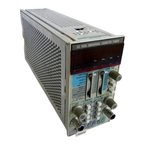
TM 9-6625-474-14&P-3 LIST OF TABLES Page Table No. Title Electrical Characteristics ....... . Miscellaneous . - Page 185 Tektronix Universal Counter/Timer, Model DC 503A. Throughout this manual, Tektronix Universal like about your equipment. Let us know why you don’t like the design.
- Page 186 TM 9-6625-474-14&P-3 Fig. 0-1. DC 503A Universal Counter/Timer...
- Page 187 TM 9-6625-474-14&P-3 SECTION 1 SPECIFICATION Instrument Options Instrument Description The DC 503A Universal Counter/Timer is designed to Option 01 replaces the internal 10 MHz time base operate in a TM 500-series power module. (clock) circuit with a self-contained proportional temperature controlled oven oscillator for increased ac- curacy and stability.
- Page 188 TM 9-6625-474-14&P-3...
- Page 189 TM 9-6625-474-14&P-3...
- Page 190 TM 9-6625-474-14&P-3...
- Page 191 TM 9-6625-474-14&P-3...
- Page 192 TM 9-6625-474-14&P-3...
- Page 193 TM 9-6625-474-14&P-3...
- Page 194 TM 9-6625-474-14&P-3...
-
Page 195: Plug-In Installation/Removal
TM 9-6625-474-14&P-3 SECTION 2 OPERATING INSTRUCTIONS press firmly to seat the circuit board edge connector in the INTRODUCTION power module interconnecting jack. Apply power to the DC 503A by operating the power switch on the power This section of the manual provides installation and module. - Page 196 TM 9-6625-474-14&P-3 CONTROLS AND CONNECTORS MODE SELECTION AND Even though the DC 503A is fully calibrated and ready to use, the functions and actions of the controls and CONTROL FUNCTIONS connectors should be reviewed before attempting to use FUNCTION: selects the measurement, events, or time counting modes for the counter.
-
Page 197: Controls And Connectors
TM 9-6625-474-14&P-3 Fig. 2-2. Controls and connectors. - Page 198 TM 9-6625-474-14&P-3 CHANNEL A INPUT AND LEVEL SOURCE: push-push switch selects the source of the input signal. Button out, EXT, selects the front FUNCTIONS panel connector as a signal source. Button in, INT, routes the input signal to the counter via the rear CH A INPUT: bnc connector for Channel A signal interface connections.
-
Page 199: Frequency A Display Check
TM 9-6625-474-14&P-3 Fig. 2-3. Triggering circuit response to improper (A) and proper (B) level settings. OPERATORS FAMILIARIZATION PREPARATION Table 2-1 FREQUENCY A DISPLAY CHECK Turn on the power module to apply power to the DC 503A. One or more characters in the display should be visible. -
Page 200: Period B, Time A - B, Width B (Timing Mode) Display Check
TM 9-6625-474-14&P-3 Table 2-2 Table 2-4 PERIOD B, TIME A - B, WIDTH B RATIO A/B AND EVENTS A (TIMING MODE) DISPLAY CHECK DURING B DISPLAY CHECK Set the FUNCTION switch to WIDTH B in the blue area Time Manual Displays of the front panel while retaining the setting of the AVG/TIMING switch;... - Page 201 TM 9-6625-474-14&P-3 Channel B Slope Channel A Slope Verify that the TOTALIZE/TIME MANUAL jumper is in Set the FUNCTION switch to PERIOD B, CH B to + SLOPE (button out), and the AVGS/TIMING switch to 1. the TOTALIZE position. With the FUNCTION switch set to Push the RESET button.
- Page 202 TM 9-6625-474-14&P-3 Table 2-5 GATE TIME MEASUREMENT RESOLUTION Measurement Rate. Once a stable measurement is preferred. Other wave shapes can be accurately measured obtained, the rate at which measurements are made can if the amplitude is kept high. be controlled by the DISPLAY TIME control. Turning the control clockwise holds off the gate and stores the display for a longer time before a new measurement is made and displayed.
-
Page 203: Representation Of Interval Measurements
TM 9-6625-474-14&P-3 Fig. 2-4. Representation of Interval measurements. Rotate the LEVEL control until the GATE indicator just Set the Channel B LEVEL control to the desired come on and record the digital voltmeter reading. triggering level as calculated in Step 2. Continue rotating the LEVEL control until the GATE indicator just goes off and record the digital voltmeter reading. -
Page 204: Typical Ch A And Ch B Level Out Voltage Settings For Various Time Interval Measurements
TM 9-6625-474-14&P-3 Fig. 2-5. Typical CH A and CH B Level Out voltage settings for various time interval measurements. EVENTS A DURING B MODE 3. Set the FUNCTION switch to EVENTS A DURING B. In the EVENTS A DURING B mode, the events applied to Channel A are counted. - Page 205 TM 9-6625-474-14&P-3 Fig. 2-6. Illustration of CH A events counted from portion of CH A signal pulses during the counter gate open time (controlled by CH B signal). In the Ratio A/B mode, the frequency of the signal measurements, the smallest number of averages that produces a useful number of digits should be considered.
- Page 206 REPACKAGING FOR SHIPMENT This mode is a manual analog of the FREQUENCY A If the Tektronix instrument is to be shipped to a mode. lnthismode, signal event sapplied tothe Channel A Tektronix Service Center for service or repair, attach a tag...
-
Page 207: Theory Of Operation
TM 9-6625-474-14&P-3 SECTION 3 THEORY OF OPERATION BLOCK DIAGRAM DESCRIPTION Introduction panel with the proper decimal point location and correct annunciator illuminated. For the following block diagram description refer to the Block Diagram foldout page at the rear of this manual. The Measurement Cycle Timing circuit determines the Display Time, clears the Gate Generator circuits, loads Channel A and Channel B Amplifiers... - Page 208 TM 9-6625-474-14&P-3 signals and the Channel A signals are counted during that time. Counts are accumulated in the decade counters during either the positive portions of the pulse widths or the TOTALIZE A negative portions, dependent on the SLOPE polarity selection for the Channel B signal.
- Page 209 TM 9-6625-474-14&P-3 counter has a 10 MHz, self contained, proportional derived from two programmable read-only memory temperature controlled oven oscillator for increased ac- (PROM) devices that look at the settings for the FUNC- curacy and stability. TlON and AVGS/TIMING Switching Logic circuits. Four of the six annunciators are also encoded with data from Power Supplies the PROM devices.
- Page 210 TM 9-6625-474-14&P-3 approximately three. The differential output from this on pin 11. The second rising edge causes U1321B to again v o l t a g e a m p l i f i e r d r i v e s t h e S c h m i t t t r i g g e r c i r c u i t , change state.
- Page 211 TM 9-6625-474-14&P-3...
- Page 212 TM 9-6625-474-14&P-3 The gate signal generated on pin 14 of U1410B is again The Gate Generator circuit also produces the Latch Trigger and a complementary Measurement Gate going to routed through and inverted by both U1330B and U1220C. the Measurement Cycle Timing circuit on schematic 5. The operation of the Latch Trigger circuit is the same for PERIOD B (Average).
- Page 213 TM 9-6625-474-14&P-3 passes through U1421C, through Q1331, out to the + N internal jumper P1020 (J1020) on schematic 9. Logic gate Circuit, and back through Q1320 to start the Gate U1420D is enabled to allow counting the Channel A Generator on the first edge. Pin 14 of U1410B goes low and signals, while U1330C is enabled to allow the Measure- sets pin 5 of U1430A low during the Measurement Gate ment Gate, generated by the Start/Stop switch, S1311, ora...
- Page 214 TM 9-6625-474-14&P-3 CR1220 to be forward biased, holding pin 9 of U1310A low operate as TTL to ECL level shifters. As the first clock and enabling that flip-flop to change state when clocked pulse on pin 5 of U1300A makes a transition from low to o n p i n 6 , W h e n t h e i n s t r u m e n t i s o p e r a t i n g i n t h e high, the output (pin 2) goes from low to high, Assuming TOTALIZE A or TIME MANUAL mode, pin 3 of U1600B is...
- Page 215 TM 9-6625-474-14&P-3 and U1621D to pin 1 of U1520 (schematic 7), telling the pins 12 and 1 of U1620 are hardwired, the 2nd DCU also decade counting units to latch the accumulated count. divides by ten. During the time that the GATE light and Load pulses When the reset signal on pin 2 of U1620 goes high, all were being generated, the ramp voltage on the emitter of four outputs are set low and U1620 counts the negative...
-
Page 216: Prom Selection Code
TM 9-6625-474-14&P-3 is made active The bcd output data is demultiplexed via D i s p l a y the time slot lines driving the eight LED’s in the display The eight digit LEDs are common cathode displays, (schematic 8). The bcd output codes area also converted to with the time slot pulses (TS1 through TS8) scanning pin 6 seven segment information by U1610. - Page 217 TM 9-6625-474-14&P-3 mode is selected by the user changing the position of U1 830, connected to the +33.5 Vdc supply. Reverse P1020 relative to the pins on J1020. This jumper is located polarity protection for the three supplies is provided by on the A12 Aux board.
- Page 218 SECTION 4 CALIBRATION PERFORMANCE CHECK PROCEDURE Introduction factory service center. Contact your local Tektronix field office or representative for further information. This procedure checks the electrical performance requirements as listed in the Specification section in this manual. Perform the Adjustment Procedure if the instru- ment fails to meet these checks.
-
Page 219: List Of Test Equipment Requirements
TM 9-6625-474-14&P-3 Table 4-1 LIST OF TEST EQUIPMENT REQUIREMENTS... - Page 220 TM 9-6625-474-14&P-3 Preliminary Control Settings TIME BASE CHECKS Series Oscilloscope 7000 1. Check Oscillator Frequency (Standard time base and Option 1) POWER FOCUS as desired for a well-defined display INTENSITY NOTE LEFT VERTICAL MODE HORIZONTAL MODE The time base accuracy is a function of temperature VERT MODE B TRIGGER SOURCE and time.
-
Page 221: Check Set-Up For The High Frequency Sensitivity Using X1 And X5 Attenuation
TM 9-6625-474-14&P-3 3. Check Totalize A and Time Manual (0 to b. Connect the DC 503A A SHAPED OUT signal to the 125 MHz) Vertical Plug-in INPUT connector using the tip jack-to- bnc connector (black terminal to COMMON). a. Turn off the power module. Remove the DC 503A. c. - Page 222 TM 9-6625-474-14&P-3 i. Re-insert plug-in into the power module. b. Set the DC 503A AVGS switch to 10’ and FUNC- TION to PERIOD B AVGS. j. To check the Time Manual, press the START/STOP pushbutton to START (in position). c. Adjust the DC 503A CH B LEVEL control for a stable display on the DC 503A and oscilloscope.
- Page 223 TM 9-6625-474-14&P-3 g. CHECK--that the DC 503A readout indicates ap- d. Remove the DC 503A CH B cable connection. Insert proximately 8,000 (nSEC) with the display GHz/nSEC the 10X attenuator with the 50 Sl termination onto the vertical i l l u m i n a t e d . plug-in INPUT.
- Page 224 TM 9-6625-474-14&P-3 l. Move the vertical plug-in INPUT connection to the e. The oscilloscope crt display is a squarewave. DC 503A CH A INPUT and re-connect the A SHAPED OUT signal to the vertical plug-in INPUT. Change the vertical plug-in VOLTS/DIV switch to .2. Adjust the CH A f.
-
Page 225: Check Set-Up For Minimum Pulse Width Signals
TM 9-6625-474-14&P-3 c. Adjust the vertical plug-in POSITION control to j. Adjust the DC 503A CH A LEVEL control forastable display on the DC 503A and oscilloscope. center the trace on the crt. Change the AC-GND-DC Switch to DC. k. CHECK-that the DC 503A readout indicates ap- proximately 125.00 (MHz) with the display MHz/@3EC d. - Page 226 TM 9-6625-474-14&P-3 j. Set the DC 503A FUNCTION switch to PERIOD B b. CHECK-the displayed GATE light blinks and the (AVGS) and the AVGS switch to 106. display readout is 0.0 (SEC) +1 count with the display Hz/SEC illuminated. k. Move the DC 503A A SHAPED OUT connector to the B SHAPED OUT (black terminal to COMMON) and 11.
- Page 227 TM 9-6625-474-14&P-3 Pulse Generator d. CHECK-the displayed GATE light blinks and the display readout is 0.0 (SEC) il count with the display PERIOD 10 ns Hz/SEC illuminated. OUTPUT (VOLTS) –1 LOW LEVEL HIGH LEVEL BACK TERM TWO CHANNEL FUNCTION CHECKS 16.
- Page 228 TM 9-6625-474-14&P-3 Digital Multimeter g. Move the DC 503A A SHAPED OUT connection to the B SHAPED OUT. RANGE 20 DC VOLTS h. Adjust the DC 503A CH B LEVEL control for a a. Turn off the power module and disconnect the pulse squarewave display on the crt.
-
Page 229: Check Set-Up For Trigger Level Range
TM 9-6625-474-14&P-3 h. Adjust the DC 503A CH A LEVEL control to center a. Turn off the power module. Insert the function the falling edge of the displayed squarewave on the center generator. Turn on the power module. vertical graticule Iine. b. - Page 230 TM 9-6625-474-14&P-3 p. Re-connect the tip jack-to-bnc cable from the k. Disconnect the INPUT cable from the digital mul- DC 503A CH A TRIG LEVEL output (black terminal to timeter and connect the function generator OUTPUT to COMMON) to the digital multimeter INPUT. the digital multimeter INPUT.
- Page 231 TM 9-6625-474-14&P-3 b. Remove the top cover from the power module, h. CHECK-that the DC 503A readout indicates ap- e x p o s i n g t h e i n t e r f a c e c o n n e c t o r s ( r e f e r t h e proximately 50.0000 (MHz) with the display MHz/pSEC...
- Page 232 TM 9-6625-474-14&P-3 ADJUSTMENT PROCEDURE Introduction VARIAC Range switch 300 w this Adjustment Procedure to restore the DC 503A to original performance requirements. This Adjustment AC VOLT meter Procedure need not be performed unless the instrument fails to meet the Performance Requirements of the Electrical characteristics listed in the Specification sec- Digital Multimeter...
- Page 233 TM 9-6625-474-14&P-3 b. The digital multimeter readout must indicate 7. Adjust the Standard Timebase Accuracy, C1715 between and Optional Timebase Accuracy, Y1710 a. Connect a coaxial cable from the WWVB Frequency 3. Check the Standard 1 MHz output signal to the DC 503A CH B INPUT.
-
Page 234: Damage
TM 9-6625-474-14&P-3 SECTION 5 MAINTENANCE GENERAL MAINTENANCE INFORMATION 9. Use a soldering iron that is connected to earth Static-Sensitive Components ground. 10. Use only special antistatic suction type or wick type resoldering tools. semiconductor Static discharge can damage any component in this instrument. Table 5-1 This instrument contains electrical components that Relative Susceptiblity to... - Page 235 Inc., to satisfy particular requirements, or are manufac- only a 15 W, pencil type soldering iron. A higher wattage tured for Tektronix, Inc., to our specifications. Most of the soldering iron can cause the etched circuit wiring to mechanical parts used in this instrument have been separate from the board base material and melt the manufactured by Tektronix, Inc.
- Page 236 Circuit Board Pins and Ferrules See Fig. 5-2. A circuit board pin replacement kit (including necessary tools, instructions, and replacement pins with attached ferrules) is available from Tektronix, Inc.; order Tektronix Part Number 040-0542-00. Replacing circuit board pins on multilayer boards is not recommend- ed.
- Page 237 TM 9-6625-474-14&P-3 Position the replacement pin in the same manner as the original. Solder the pin to the circuit board on each side of the board. If the original pin was bent at an angle to mate with a connector, carefully bend the new pin to the same angle.
- Page 238 9-6625-474-14&P-3 Circuit Board Removal Remove the two screws and two fasteners attaching the rear of the plug-in frame. See Fig. 5-6. The bottom fasteners require a 3/16 inch wrench. Remove the front panel knob connected to the DISPLAY. Unsolder the wires to the front panel connectors.
- Page 239 9-6625-474-14&P-3 REAR INTERFACE INFORMATION FUNCTIONS AVAILABLE AT REAR Channel B Level Out 22B CONNECTOR The voltage at this connection follows the channel B front panel trigger LEVEL control. The source impedance A slot exists between pins 21 and 22 on the rear is 1 k~ and the signal level is between *3.5 V.
- Page 240 TM 9-6625-474-14&P-3 Fig. 5-9. Rear interface connector assignments.
- Page 241 TM 9-6625-474-14&P3 Fig. 5-10. Rear interface timing for a display of 1079.0674. Reset In/Out 26A TTL Clock input 21A This input a single low power Schottky TTL load. The This line goes low when the counters are reset. This line circuitry driving this input must source 20 LA for a high also goes low when the front panel RESET button is input and sink 0.36 mA when driving low.
- Page 242 For further information on instrument options or optional accessories, see your Tektronix Catalog or contact your Tektronix Field Office. If additional options are made available for this instrument, they may be described in a Change Information insert at the back of this manual or in this section.
- Page 243 If a part you have ordered has been replaced with a new or assemblies and parts). improved part, your local Tektronix, Inc. Field Office or represen- Chassis-mounted parts have no assembly number prefix tative will contact you concerning any change in part number.
- Page 244 TM 9-6625-474-14&P-3 CROSS INDEX–MFR. CODE NUMBER TO MANUFACTURER Mfr. Code Manufacturer Address City, State, Zip...
- Page 245 TM9-6625-474-14&P-3 TEKTRONIX SERIAL/MODEL NO. COMPONENT NO. PART NO. EFF DSCONT NAME & DESCRIPTION CODE 670-6556-00 CKT BOARD ASSY:DISPLAY 80009 670-6557-00 CKT BOARD ASSY:AUXILIARY 80009 670-6558-00 CKT BOARD ASSY:MAIN 80009 670-6559-00 CKT BOARD ASSY:MAIN 80009 (OPTION 1 ONLY) CKT BOARD ASSY:DISPLAY...
- Page 246 TM9-6625-474-14&P-3 TEKTRONIX SERIAL/MODEL NO. COMPONENT NO. PART NO. DSCONT NAME & DESCRIPTION CODE MFR PART NUMBER A12C1600 281-0775-00 CAP.,FXD,CER DI:0.1UF,20%,50V 72982 8005D9AABZ5U104M A12C1622 281-0775-00 CAP.,FXD,CER DI:0.1UF,20%,50V 72982 8005D9AABZ5U104M A12C1629 281-0775-00 CAP.,FXD,CER DI:0.1UF,20%,50V 72982 8005D9AABZ5U104M A12C1630 281-0775-00 CAP.,FXD,CER DI:0.1UF,20%,50V 72982 8005D9AABZ5U104M...
- Page 247 TM9-6625-474-14&P-3 TEKTRONIX SERIAL/MODEL NO. COMPONENT NO. PART NO. DSCONT NAME & DESCRIPTION CODE MFR PART NUMBER A12R1033 315-0361-00 RES.,FXD,CMPSN:360 OHM,5%,0.25W 01121 CB3615 A12R1035 315-0681-00 RES.,FXD.CMPSN:680 OHM,5%,0.25W 01121 CB6815 A12R1036 315-0362-00 RES.,FXD.CMPSN:3.6K OHM,5%,0.25W 01121 CB3625 A12R1037 315-0132-00 RES.,FXD.CMPSN:1.3K OHM,5%,0.25W 01121 CB1325...
- Page 248 TM9-6625-474-14&P-3 TEKTRONIX SERIAL/MODEL NO. COMPONENT NO. PART NO. DSCONT NAME & DESCRIPTION CODE MFR PART NUMBER A12R1627 315-0680-00 RES.,FXD,CMPSN:68 0HM,5%,0.25W 01121 CB6805 A12R1628 321-0481-00 RES.,FXD.FILM:1M 0HM,1%,0.125W 24546 NA4D1004F A12R1629 315-0154-00 RES.,FXD.CMPSN:150K 0HM,5%,0.25W 01121 CB1545 A12R1630 315-0131-00 RES.,FXD.CMPSN:130 0HM,5%,0.25W 01121 CB1315...
- Page 249 TM9-6625-474-14&P-3 TEKTRONIX SERIAL/MODEL NO. COMPONENT NO. PART NO. DSCONT NAME & DESCRIPTION CODE MFR PART NUMBER CKT BOARD ASSY:MAIN A14C1030 283-0057-00 CAP.,FXD,CER DI:0.1UF,+80-20%,200V 56289 274C10 A14C1120 283-0359-00 CAP.,FXD,CER DI:1000PF,10%,200V 72982 8131N203C0G0102K A14C1130 281-0622-00 CAP.,FXD,CER DI:47PF,1%,500V 72982 308-000C0G0470F A14C1131 281-0716-00 CAP.,FXD,CER DI:13.8PF,1%,500V...
- Page 250 TM9-6625-474-14&P-3 TEKTRONIX SERIAL/MODEL NO. COMPONENT NO. PART NO. DSCONT NAME & DESCRIPTION CODE MFR PART NUMBER A14CR1230 152-0141-02 SEMICOND DEVICE:SILICON,30V.150MA 01295 1N4152R A14CR1700 152-0141-02 SEMICOND DEVICE:SILICON,30V,150M 01295 1N4152R A14CR1721 152-0141-02 SEMICOND DEVICE:SILICON,30V,150MA 01295 1N4152R A14CR1730 152-0066-00 SEMICOND DEVICE:SILICON,400V,750MA 14433 LG4016...
- Page 251 TM9-6625-474-14&P-3 TEKTRONIX SERIAL/MODEL NO. COMPONENT NO. PART NO. DSCONT NAME & DESCRIPTION CODE MFR PART NUMBER A14R1110 315-0512-00 RES.,FXD,CMPSN:5.1K 0HM,5%,0.25W 01121 CB5125 A14R1120 315-0391-00 RES.,FXD.CMPSN:390 0HM,5%,0.25W 01121 CB3915 A14R1130 315-0102-00 RES.,FXD,CMPSN:1K 0HM,5%,0.25W 01121 CB1025 A14R1132 315-0510-00 RES.,FXD.CMPSN:51 0HM,5%,0.25W 01121 CB5105...
- Page 252 TM9-6625-474-14&P-3 TEKTRONIX SERIAL/MODEL NO. COMPONENT NO. PART NO. DSCONT NAME & DESCRIPTION CODE MFR PART NUMBER A14R1410 311-2096-00 RES.,VAR,NONWW:PANL,1M 0HM,20%,0.5W 12697 SERIES 388 (FURNISHED AS A UNIT WITH A14S1410) A14R1412 315-0123-00 RES.,FXD.CMPSN:12K 0HM,5%,0.25W 01121 CB1235 A14R1420 311-1559-00 RES.,VAR,NONWIR:10K 0HM,20%,0.50W 73138...
- Page 253 TM9-6625-474-14&P-3 TEKTRONIX SERIAL/MODEL NO. COMPONENT NO. PART NO. DSCONT NAME & DESCRIPTION CODE MFR PART NUMBER A14R1803 321-0213-00 RES.,FXD,FILM:1.62K 0HM,1%,0.125W 91637 MFF1816G16200F (OPTION 1 ONLY) A14R1810 315-0100-00 RES.,FXD,CMPSN:10 0HM,5%,0.25W 01121 CB1005 A14R1820 315-0132-00 RES.,FXD,CMPSN:1.3K 0HM,5%,0.25W 01121 CB1325 A14R1821 315-0152-00 RES.,FXD,CMPSN:1.5K 0HM,5%,0.25W...
- Page 254 TM9-6625-474-14&P-3 TEKTRONIX SERIAL/MODEL NO. COMPONENT NO. PART NO. DSCONT NAME & DESCRIPTION CODE MFR PART NUMBER CHASSIS PARTS J510 131-0955-00 CONN,RCPT,ELEC:BNC,FEMALE 13511 31-279 J520 136-0387-00 JACK,TIP:GRAY 71279 450-4352-01-0318 J530 136-0387-00 JACK,TIP:GRAY 71279 450-4352-01-0318 J540 136-0387-00 JACK,TIP:GRAY 71279 450-4352-01-0318 J610 131-0955-00 CONN,RCPT.ELEC:BNC,FEMALE...
- Page 255 Values less than one are in microfarads Other ANSI standards that are used in the preparation Resistors = Ohms (fl). of diagrams by Tektronix, Inc. are: — The information and special symbols below may appear in this manual.— Assembly numbers and Grid Coordinates The schematic diagram and circuit board component location illustration have grids.
- Page 256 TM 9-6625-474-14&P-3...
- Page 258 TM 9-6625-474-14&P-3 ADJUSTMENT LOCATIONS...
- Page 259 TM 9-6625-474-14&P-3 PARTS LOCATION GRID Table 8-1 COMPONENT REFERENCE CHART (See Fig. 8-3)
- Page 261 TM 9-6625-474-14&P-3 Table 8-2 PARTS LOCATION GRID COMPONENT REFERENCE CHART (See Fig. 8-4)
- Page 263 TM 9-6625-474-14&P-3 Table 8-3 COMPONENT REFERENCE CHART (See Fig. 8-3)
- Page 264 TM 9-6625-474-14&P-3...
- Page 265 TM 9-6625-474-14&P-3 Table 8-4 COMPONENT REFERENCE CHART (See Fig. 8-3)
- Page 266 TM 9-6625-474-14&P-3...
- Page 267 TM 9-6625-474-14&P-3 DC 503A Table 8-5 COMPONENT REFERENCE CHART (See Fig. 8-4)
- Page 268 TM 9-6625-474-14&P-3...
- Page 269 TM 9-6625-474-14&P-3 DC 503A Table 8-6 COMPONENT REFERENCE CHART (See Fig. 8-3)
- Page 270 TM 9-6625-474-14&P-3...
- Page 271 TM 9-6625-474-14&P-3 DC 503A Table 8-7 COMPONENT REFERENCE CHART (See Fig. 8-4)
- Page 272 TM 9-6625-474-14&P-3...
- Page 273 TM 9-6625-474-14&P-3 DC 503A PARTS LOCATION GRID Table 8-8 COMPONENT REFERENCE CHART...
- Page 274 TM 9-6625-474-14&P-3...
- Page 275 9-6625-474-14&P-3 DC 503A Table 8-9 COMPONENT REFERENCE CHART (See Fig. 8-3)
- Page 276 9 - 6 6 2 5 - 4 7 4 - 1 4 & P - 3...
- Page 277 TM 9-6625-474-14&P-3 DC 503A Table 8-10 COMPONENT REFERENCE CHART (See Fig. 8-4)
- Page 278 TM 9-6625-474-14&P-3...
- Page 279 ..If a part you have ordered has been replaced with a new or Parts of Detail Part improved part, your local Tektronix, Inc Field Office or Attaching parts for Parts of Detail Part ..
- Page 280 TM 9-6625-474-14&P-3 CROSS INDEX-MFR. CODE NUMBER T0 MANUFACTURER City, State, Z Address Mfr. Code Manufacturer...
- Page 281 TM9-6625-474-14&P-3 FIG. & INDEX TEKTRONIX SERIAL/MODEL NO. PART NO. DSCONT QTY 1 2 3 4 5 NAME & DESCRIPTION CODE MFR PART NUMBER 337-1399-11 SHIELD,ELEC:RIGHT SIDE 80009 337-1399-11 337-1399-10 SHIELD,ELEC:LEFT SIDE 80009 337-1399-10 366-1023-07 KNOB:GRAY,0.127 ID,0.392 OD,0.466 80009 366-1023-07 366-0494-05 KNOB:GRAY,0.127 IDX 0.5 OD,0.531H...
- Page 282 TM9-6625-474-14&P-3 FIG. & INDEX TEKTRONIX SERIAL/MODEL NO. PART NO. DSCONT QTY 1 2 3 4 5 NAME & DESCRIPTION CODE MFR PART NUMBER 1-42 337-2804-00 SHIELD,ELEC:CIRCUIT BOARD 80009 337-2804-00 TERMINAL,PIN:(SEE A12J1519,J1530,J1630, J1730 EPL) 131-0993-00 BUS,CONDUCTOR:2 WIRE BLACK 00779 530153-2 136-0252-07...
- Page 283 TM9-6625-474-14&P-3 FIG. & INDEX TEKTRONIX SERIAL/MODEL NO. PART NO. DSCONT QTY 1 2 3 4 5 NAME & DESCRIPTION CODE MFR PART NUMBER WIRE ASSEMBLIES 175-2984-00 CA ASSY,RF:50 OHM COAX.6.0 L 80009 175-2984-00 (FROM A12J1522 TO J520) 352-0169-00 HLDR.TERM CONN:2 WIRE BLACK...
- Page 284 TM 9-6625-474-14&P-3 APPENDIX A REFERENCES Index of Technical Manuals, Technical Bulletins, Supply Manuals DA PAM 310-4 (Types 7, 8, and 9), Supply Bulletins, and Lubrication orders Index of US Army Equipment Modification Work Orders DA PAM 310-7 First Aid for Soldiers FM 21-11 AR 385-40 Accident Reporting and Records...
- Page 285 TM 9-6625-474-14&P-3 APPENDIX B MAINTENANCE ALLOCATION CHART Section 1. INTRODUCTION B-1. GENERAL. a. This section provides a general explanation of all maintenance and repair functions authorized at various maintenance categories. b. The Maintenance Allocation Chart (MAC) in Section II designates overall authority and responsibility for the performance of maintenance functions on the identified end items or component.
- Page 286 TM 9-6625-474-14&P-3 j. Overhaul. That maintenance effort (service/action) prescribed to restore an item to a completely serviceable-operational condition as required by maintenance standard in appropriate technical publications. Overhaul is normally the highest degree of maintenance performed by the Army. Overhaul does not normally return an item to like-new condition.
- Page 287 TM 9-6625-474-14&P-3 e. Column 5, Tools and Test Equipment. Column 5 specifies, by code, those common tools sets (not individual tools) and special tools, TMDE, and support equipment required to perform the designated function. f. Column 6, Remarks. This column shall, when applicable, contain a letter code, in alphabetic order, which shall be keyed to the remarks contained in Section IV.
- Page 288 TM 9-6625-474-14&P-3 CHART SECTION Il. MAINTENANCE ALLOCATION TEKTRONIX DC 503A UNIVERSAL COUNTER Fig 1 SECTION III. TOOL AND TEST EQUIPMENT REQUIREMENTS TEKTRONIX DC 503A UNIVERSAL COUNTER...
- Page 289 TM 9-6625-474-14&P-3 SECTION IV. REMARKS REFERENCE REMARKS CODE Organizational maintenance will be accomplished by the organization owning and using the equipment. All special tools and test equipment are called out in Table 4-1. Supply of parts will be through normal supply channels. A recommended repair parts list will be published as part of this manual.
- Page 290 TM9-6625-474-14&P-3 APPENDIX C RECOMMENDED SPARE PARTS LIST TEKTRONIX DC 503A UNIVERSAL COUNTER ITEM TEKTRONIX PART NO. ITEM NAME REC. QTY 136-0387-00 JACK, TIP 366-1512-00 PUSH BUTTON 670-6556-01 CIRCUIT BD ASSY 672-0103-00 CIRCUIT BD ASSY C-1/(C-2 BLANK)
- Page 291 TM 9-6625-474-14&P-3 APPENDIX MANUAL CHANGE INFORMATION...
- Page 292 TM 9-6625-474-14&P-3...
- Page 293 TM 9-6625-474-14&P-3 P a g e 1 o f 2...
- Page 294 TM 9-6625-474-14&P-3...
- Page 295 TM 9-6625-474-14&P-3 DESCRIPTION EFF SN B022560 (DC 503A) EFF SN B022710 (DC 503A -Option 01) REPLACABLE ELECTRICAL PARTS AND SCHEMATIC CHANGES CHANGE TO: 670-6556-01 CKT BOARD ASSY:MAIN 670-6559-01 CKT BOARD ASSY:MAIN (OPTION 1 ONLY) 281-0852-00 A14C1431 CAP., FXD, CER DI : 1800 PF, 10%, 100V RES., FXD, CMPSN : 5.lK 0HM, 5%, 0.25W A14R1531 315-0512-00...
- Page 296 TM 9-6625-474-14&P-3...
- Page 297 By Order of the Secretary of the Army: JOHN A. WICKHAM, JR. General, United States Army Chief of Staff Official: ROBERT M. JOYCE Major General, United States Army The Adjutant General Distribution: To be distributed in accordance with DA Form 12-37, Block 1097, Organizational Maintenance requirements for Bradley Fighting Vehicle TOW Subsystem.
- Page 299 THE METRIC SYSTEM AND EQUIVALENTS...
- Page 300 PIN: 056816-000...
Need help?
Do you have a question about the DC503a and is the answer not in the manual?
Questions and answers