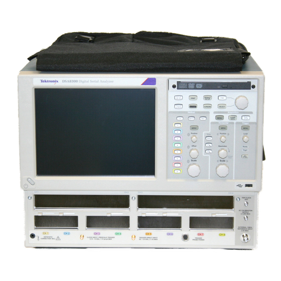
Tektronix DSA8300 Service Manual
Digital serial analyzer, sampling modules
Hide thumbs
Also See for DSA8300:
- Programmer's manual (455 pages) ,
- Technical reference (277 pages) ,
- Service manual (138 pages)

Related Manuals for Tektronix DSA8300


Summary of Contents for Tektronix DSA8300
- Page 1 DSA8300 Digital Serial Analyzer 80A00, 80C00, 80E00 Sampling Modules Service Manual *P077057201* 077-0572-01...
- Page 3 DSA8300 Digital Serial Analyzer 80A00, 80C00, 80E00 Sampling Modules Service Manual Revision A June 2015 Warning The servicing instructions are for use by qualified personnel only. To avoid personal injury, do not perform any servicing unless you are qualified to do so. Refer to all safety summaries prior to performing service.
- Page 4 Copyright © Tektronix. All rights reserved. Licensed software products are owned by Tektronix or its subsidiaries or suppliers, and are protected by national copyright laws and international treaty provisions. Tektronix products are covered by U.S. and foreign patents, issued and pending. Information in this publication supersedes that in all previously published material.
-
Page 5: Table Of Contents
Removal and installation..................Required equipment ..................External assemblies................... Line fuses and AC power cord ................. Front-Panel knobs..................Trim and carrying handle ................Bottom cover ..................... Left and right covers..................Internal assemblies ................... DSA8300 Digital Serial Analyzer and Modules Service Manual... - Page 6 Checking the power supply voltages ............... PPC and ATX PC diagnostics ................BIOS beep codes....................Firmware updates ..................... After repair ....................Reloading instrument model and serial number ............Repackaging instructions ..................Replaceable parts list....................DSA8300 Digital Serial Analyzer and Modules Service Manual...
- Page 7 Figure 26: 80A05 module (Option 10G shown) ............... Figure 27: 80E06 module..................Figure 28: 80E07/B, 80E08/B, 80E09/B, and 80E10/B modules ..........Figure 29: Optical modules (all) ................. Figure 30: 80A01 module ..................Figure 31: 82A04B module ..................DSA8300 Digital Serial Analyzer and Modules Service Manual...
- Page 8 Table 13: 80E07/B, 80E08/B, 80E09/B, and 80E10/B modules replaceable parts list ....Table 14: 80C00 Optical modules replaceable parts list (all optical modules) ......Table 15: 80A01 module replaceable parts list..............Table 16: 82A04B module replaceable parts list............... DSA8300 Digital Serial Analyzer and Modules Service Manual...
-
Page 9: Important Safety Information
To reduce the risk of fire and shock, make sure that the mains supply voltage fluctuations do not exceed 10% of the operating voltage range. Use proper power cord. Use only the power cord specified for this product and certified for the country of use. DSA8300 Digital Serial Analyzer and Modules Service Manual... - Page 10 Use proper fuse. Use only the fuse type and rating specified for this product. Do not operate in wet/damp conditions. Be aware that condensation may occur if a unit is moved from a cold to a warm environment. DSA8300 Digital Serial Analyzer and Modules Service Manual...
-
Page 11: Service Safety Summary
The product is heavy. To reduce the risk of personal injury or damage to the device get help when lifting or carrying the product. Use only the Tektronix rackmount hardware specified for this product. Service safety summary The Service safety summary section contains additional information required to safely perform service on the product. -
Page 12: Terms In This Manual
find out the nature of the potential hazards and any actions which have to be taken to avoid them. (This symbol may also be used to refer the user to ratings in the manual.) The following symbol(s) may appear on the product: viii DSA8300 Digital Serial Analyzer and Modules Service Manual... -
Page 13: Compliance Information
Compliance information See the DSA8300 Digital Serial Analyzer Quick Start User Manual for information on instrument compliance. Environmental considerations See the DSA8300 Digital Serial Analyzer Quick Start User Manual for information on instrument environmental considerations. DSA8300 Digital Serial Analyzer and Modules Service Manual... - Page 14 Compliance information DSA8300 Digital Serial Analyzer and Modules Service Manual...
-
Page 15: Preface
Preface This is the service manual for the DSA8300 Digital Serial Analyzer and the modules that install in the instrument (except for the 80A03 module). NOTE. The 80A03 instruction manual contains its own specifications and servicing information. Read this preface to learn how this manual is structured, what conventions it uses, and where you can find other information related to servicing this product. -
Page 16: Related Documentation
80A03 TekConnect Probe Interface Module Instructions. 071-1298-XX 82A04B Phase Reference Module User manual. 077-3124-XX Rackmount Kit Instructions. 071-0696-XX Check the Tektronix Web site (www.tek.com/downloads) for the most current version of these documents. DSA8300 Digital Serial Analyzer and Modules Service Manual... -
Page 17: Operating Information
80C00 and 80E00 Series Sampling Modules Installing sampling modules, connecting cables, cleaning optical connectors User Manual, Tektronix part number 071-3059-XX DSA8300 Specifications Technical Instrument and module specifications Reference, Tektronix part number 077-0571-XX DSA8300 Digital Serial Analyzer and Modules Service Manual... - Page 18 Technical Reference, Tektronix part number procedures 077-0682-XX Product software install instructions, System hard drive rebuild procedure Tektronix part number 071-2050-XX Shipped Software release notes with the product software disc. Software installation Operating system reinstallation DSA8300 Digital Serial Analyzer and Modules Service Manual...
-
Page 19: Theory Of Operation
The platform features XGA resolution flat-panel display, transparent touch screen and user front-panel with direct access to commonly used oscilloscope functions. The instrument is also equipped with a mouse and keyboard for access to more advanced functions. DSA8300 Digital Serial Analyzer and Modules Service Manual... -
Page 20: Mainframe Overview
Theory of operation Mainframe overview This mainframe overview describes the basic operation of each functional circuit block as shown in the following figure: Figure 1: DSA8300 block diagram DSA8300 Digital Serial Analyzer and Modules Service Manual... - Page 21 Wintel motherboard. The CD-RW/DVD drive enables you to load software to customize your instrument for your measurement needs and to save data to a writable CD. DSA8300 Digital Serial Analyzer and Modules Service Manual...
-
Page 22: Electrical Sampling Modules
Settings derived from this reference are stored in a nonvolatile EEPROM in the sampling module, although the responsibility for the execution of these settings is with the mainframe. DSA8300 Digital Serial Analyzer and Modules Service Manual... -
Page 23: Optical Sampling Modules
An amplified or nonamplified O/E converter. Support for internal RF switches in the signal path with a straight-through path and three hardware-filtered reference receiver paths between the O/E converter and the sampler. An averaging optical power meter. DSA8300 Digital Serial Analyzer and Modules Service Manual... - Page 24 Many 80C00 modules have integral clock recovery (standard or as an option), with internal coaxial connection of the recovered clock signal to the mainframe trigger, front panel clock and data output connectors (not all have data). DSA8300 Digital Serial Analyzer and Modules Service Manual...
-
Page 25: 80A01 Trigger Prescale Preamplifier Module
Input and Output at the module front panel. The module receives power from the main instrument through a single connector at the rear of the module. The power LED indicates the module is receiving power through the interface connector. DSA8300 Digital Serial Analyzer and Modules Service Manual... -
Page 26: 80A02 Eos/Esd Protection Module
The 80A02 EOS/ESD module is designed to work with the Tektronix P8018 probe for manual and automated test station static protection. -
Page 27: 82A04B Phase Reference Module
2.5 GHz - 25 GHz (82A04B), or 2.5 GHz - 60 GHz (82A04B-60G). The LED on the module indicates that the module is being used for phase correction. DSA8300 Digital Serial Analyzer and Modules Service Manual... - Page 28 Theory of operation DSA8300 Digital Serial Analyzer and Modules Service Manual...
-
Page 29: Adjustment Procedures
The only time you should perform the Adjustment Procedures is if the instrument fails any of the mainframe performance verification checks provided in the DSA8300 Performance Verification Technical Reference manual. -
Page 30: Equipment Hookup
2. Set the National Instruments GPIB Interface command software to enable GPIB communications between the PC controller and the DSA8300. 3. Allow the test equipment and DSA8300 to warm up for at least 20 minutes before starting the adjustment procedures. -
Page 31: Adjust Dc Calibration
3. Turn off the DSA8300 cal constant protection by entering the following GPIB command: SYST:PROT OFF 4. Set the DSA8300 DC calibrator offset cal constant to 0 by entering the following GPIB command: CALCOMP:DOUBLE "DcCalOffsetAdj",0.0 5. Wait 8 seconds, and then set the instrument DC calibrator Lsb cal constant to 1.0 by entering the following GPIB command:... -
Page 32: Verify Dc Calibrator Adjustment
4. Verify that the DMM reads 1.0 V (±1 mV). 5. Set the instrument DC calibrator to 0.0 V by entering the following GPIB command: CALIBRATE:DCCALIBRATOR 0.0 6. Verify that the DMM reads 0.0 V (±0.1 mV). DSA8300 Digital Serial Analyzer and Modules Service Manual... -
Page 33: Internal 10 Mhz Adjust
To prevent incorrect calibration values, make sure that the DSA8300 and test equipment have warmed up for at least 20 minutes before performing this procedure, and that compensation was run on the DSA8300 since the last power-up or if temperature has deviated by 5 °C since the last compensation. - Page 34 “CALCOMP:DOUBLE "Internal10MHzRefFreq", 10e6 7. Record the TDR Clock Out frequency (Reading 1). 8. Set the DSA8300 TDR 10 MHz Reference trigger mode to Internal. 9. Record the TDR Clock Out frequency (Reading 2). 10. Enter the following GPIB command: “CALComp:DOUBLE...
-
Page 35: Maintenance
Do not place anything capable of generating or holding a static charge on the work station surface. Remove sampling modules or module extenders from the DSA8300 before performing removal or installation procedures on the instrument. Handle circuit boards by the edges when possible. -
Page 36: Inspection And Cleaning
If the display is very dirty, moisten the wipe with distilled water or a 75% isopropyl alcohol solution and gently rub the display surface. Avoid using excess force or you may damage the plastic display surface. DSA8300 Digital Serial Analyzer and Modules Service Manual... - Page 37 Repair or replace defective feet assembly. Accessories Missing items or parts of Repair or replace damaged items, bent pins, broken or or missing items, frayed frayed cables, and damaged cables, and defective connectors. assemblies. DSA8300 Digital Serial Analyzer and Modules Service Manual...
- Page 38 If, after performing steps 1 and 2, an assembly is clean upon inspection, skip the remaining steps. 3. Gain access to the parts to be cleaned by removing easily accessible shields and panels. (See page 24, Removal and installation.) DSA8300 Digital Serial Analyzer and Modules Service Manual...
- Page 39 6. Dry all parts with low-pressure, deionized air. 7. Dry all components and assemblies in an oven or drying compartment using low-temperature (125 °F to 150 °F) circulating air. Lubrication There is no periodic lubrication required for this instrument. DSA8300 Digital Serial Analyzer and Modules Service Manual...
-
Page 40: Removal And Installation
General and Service Safety summaries at the beginning of this manual. CAUTION. Perform all DSA8300 removal and installation procedures in a static-controlled environment, following the precautions listed in the Preventing ESD section. (See page 19.) NOTE. -
Page 41: External Assemblies
External assemblies WARNING. Before performing any procedure in this section, disconnect the power cord from the line voltage source. Failure to do so could cause serious injury or death. DSA8300 Digital Serial Analyzer and Modules Service Manual... -
Page 42: Figure 2: External Assemblies
Removal and installation Figure 2: External assemblies DSA8300 Digital Serial Analyzer and Modules Service Manual... -
Page 43: Line Fuses And Ac Power Cord
flat-bladed screwdriver, and remove the line fuses. Reverse the procedure to reinstall. 4. To remove line cord: Pull the AC power cord from the rear-panel connector to remove the AC power source. DSA8300 Digital Serial Analyzer and Modules Service Manual... -
Page 44: Front-Panel Knobs
3. To reinstall a knob: a. Align the knob to the shaft. b. While applying pressure to the back of the encoder, push the knob in until it snaps. DSA8300 Digital Serial Analyzer and Modules Service Manual... -
Page 45: Trim And Carrying Handle
Use a torque wrench to tighten the screws to 8-10 in.lb. 5. To reinstall the covers and handle: Reverse the steps. Use a torque wrench to tighten the handle screws to 8–10 in. lb. DSA8300 Digital Serial Analyzer and Modules Service Manual... -
Page 46: Bottom Cover
Be careful not to bind or snag the covers on the internal cabling of the instrument as you remove or install the covers. 3. To reinstall the left and right covers: Reverse the steps. DSA8300 Digital Serial Analyzer and Modules Service Manual... -
Page 47: Internal Assemblies
Removal and installation Internal assemblies Before removing internal assemblies, you must remove the external assemblies. (See page 25, External assemblies.) Figure 4: Internal assemblies DSA8300 Digital Serial Analyzer and Modules Service Manual... -
Page 48: Front-Panel Assembly
1 index mark on the connector and the black stripe on the cable for later reassembly. g. Pull the Front-Panel assembly forward and remove it from the instrument. 3. To reinstall the Front-Panel assembly: Reverse the steps. DSA8300 Digital Serial Analyzer and Modules Service Manual... -
Page 49: Front Panel Board
3. To reinstall the Front-Panel board: Reverse the steps. Verify that the plastic bezel is flush against the sheet metal. If it is not, the board might not be seated properly over the plastic posts. DSA8300 Digital Serial Analyzer and Modules Service Manual... -
Page 50: Front Panel Keypad
Standby/On switch flex circuit) cannot be individually ordered or replaced. If there is a problem with one of these components, return the instrument to Tektronix for repair. See the Contacting Tektronix information at the front of this manual. - Page 51 Remove the Display assembly from the instrument. To reinstall the Display assembly: Reverse the steps. Refer to the cable connections table for information about where to connect cables. (See page 72, Cable connections.) DSA8300 Digital Serial Analyzer and Modules Service Manual...
-
Page 52: Display Adapter Board
Remove the four T-15 Torx drive screws that attach the Display Adapter board to the Display assembly. (See Figure 22.) c. Remove the Display Adapter board from the Display assembly. 3. To reinstall the Display Adapter board: Reverse the steps. (See Figure 8.) DSA8300 Digital Serial Analyzer and Modules Service Manual... -
Page 53: Figure 7: Display Adaptor Board Removal
Removal and installation Figure 7: Display adaptor board removal DSA8300 Digital Serial Analyzer and Modules Service Manual... -
Page 54: Standby/On Switch Flex Circuit
The Standby/On switch flex circuit is a part of the Display assembly, and is not individually customer-replaceable. If this component must be replaced, you circuit must return the instrument to Tektronix for repair. See the Contacting Tektronix information at the front of this manual. For reference, refer to the exploded view. (See Figure 22.) -
Page 55: Usb Assembly
2. To reinstall the USB assembly: Reverse the steps. Refer to the cable connections table for information about where to connect cables. (See page 72, Cable connections.) Figure 9: USB assembly removal DSA8300 Digital Serial Analyzer and Modules Service Manual... -
Page 56: Hard Disk Drive
Slide the assembly into the instrument. d. Install the two thumbscrews to attach the assembly to the instrument. Refer to the cable connections table for information about where to connect cables. (See page 72, Cable connections.) DSA8300 Digital Serial Analyzer and Modules Service Manual... -
Page 57: Dvd-Rw Drive Assembly
Remove the two Phillips screws that hold the CD/DVD-RW drive trim to the mounting frame and remove the trim. c. Place one thumb on each side of the front of the CD/DVD-RW drive and your forefingers on the back of the drive. DSA8300 Digital Serial Analyzer and Modules Service Manual... -
Page 58: Figure 11: Cd-Rw/Dvd Assembly Removal
4. Detach the interface circuit board from the CD/DVD-RW drive. 5. To reinstall the assembly: Reverse the steps. Refer to the cable connections table for information about where to connect cables. (See page 72, Cable connections.) DSA8300 Digital Serial Analyzer and Modules Service Manual... -
Page 59: Cd/Dvd-Rw And Hard Disk Drive Mounting Frame
Remove the six T-15 Torx drive screws that attach the mounting frame to the ATX chassis. c. Remove the CDD/HDD drive cable from the hard drive. d. Remove the CD/DVD-RW drive cable from the CD/DVD-RW drive. DSA8300 Digital Serial Analyzer and Modules Service Manual... -
Page 60: Figure 13: Hard Drive And Cd-Rw/Dvd Drive Mounting Frame Removal
3. To reinstall the mounting frame: Reverse the steps. Refer to the cable connections table for information about where to connect cables. (See page 72, Cable connections.) Figure 13: Hard drive and CD-RW/DVD drive mounting frame removal DSA8300 Digital Serial Analyzer and Modules Service Manual... -
Page 61: Atx Assembly
NOTE. If this circuit board or chassis must be replaced, you must return the product to Tektronix for repair and calibration. See the Contacting Tektronix information at the front of this manual. 1. To access the assembly, remove these assemblies: Trim (all) (See page 29.) -
Page 62: Figure 14: Atx Assembly Removal
Removal and installation Figure 14: ATX assembly removal DSA8300 Digital Serial Analyzer and Modules Service Manual... -
Page 63: Power Pc Board
Lift the Power PC board out of the instrument. 3. To reinstall the Power PC board: Reverse the steps. Refer to the cable connections table for information about where to connect cables. (See page 72, Cable connections.) DSA8300 Digital Serial Analyzer and Modules Service Manual... -
Page 64: Figure 15: Power Pc Board Removal
Removal and installation Figure 15: Power PC board removal DSA8300 Digital Serial Analyzer and Modules Service Manual... -
Page 65: Power Side Board
3. To reinstall the Bridge board: Reverse the steps. Refer to the cable connections table for information about where to connect cables.(See page 72, Cable connections.) Make sure that the cables are fully seated. DSA8300 Digital Serial Analyzer and Modules Service Manual... -
Page 66: Fan Assembly
“Left” to the cable extender matched with J391. Connect the cable marked “Right” to the cable extender matched with J390. Refer to the cable connections table for more information about where to connect cables. (See page 72, Cable connections.) DSA8300 Digital Serial Analyzer and Modules Service Manual... -
Page 67: Figure 16: Fan Assembly Removal
Removal and installation Figure 16: Fan assembly removal DSA8300 Digital Serial Analyzer and Modules Service Manual... -
Page 68: Low-Voltage Power Supply
Bottom cover (See page 30.) Left and Right covers (See page 30.) Power Side board (See page 49.) Disconnect the cable (Tektronix part number 174-4241-01) from J01 on the Electrical Front-End board, allowing the clip that holds the cable to remain in place. - Page 69 Electrical Front-End circuit board and chassis, and the Optical Front-End circuit board and chassis. The circuit boards are not customer replaceable. If any of these circuit boards must be replaced, return the instrument to Tektronix for repair. DSA8300 Digital Serial Analyzer and Modules Service Manual...
-
Page 70: Electrical Sampling Modules
Sampling modules, as an entire module assembly, to a Tektronix service center for repair. Do not remove front panels or covers. You can exchange the sampling module at your local Tektronix service center or through the central Tektronix exchange in Beaverton, Oregon. See the Contacting Tektronix information at the front of this manual. -
Page 71: Figure 17: Sample Of Electrical Module Hardware Removal
Electrical shock may occur. Always power the instrument down before attempting to remove or insert any sampling module to avoid potential injury from shock. 2. Install the electrical sampling module into one of the instrument small module compartments. DSA8300 Digital Serial Analyzer and Modules Service Manual... -
Page 72: Optical Sampling Modules
Do not attempt component-level repair of any optical sampling modules. When an optical module requires repair or replacement, return the entire module to Tektronix. Do not remove the cover to reuse the serial number. DSA8300 Digital Serial Analyzer and Modules Service Manual... -
Page 73: 80A00 And 82A00 Series Modules
To prevent damage from static discharge, have a qualified service technician do module disassembly/assembly work at a static-free work station, wearing wrist and foot grounding straps at all times while handling the module chassis. Minimize handling of static-sensitive components. DSA8300 Digital Serial Analyzer and Modules Service Manual... -
Page 74: Figure 18: 80A00 And 82A00 Series Module Disassembly
Remove all coaxial terminators from the front panel connectors. b. Remove the screw on the top near the center of the front panel edge. Flip the module on the top side (bottom up). DSA8300 Digital Serial Analyzer and Modules Service Manual... - Page 75 Align the holes and attach the label to the new front panel. b. If installing a replacement cover, perform the following steps before replacing the cover: Remove the backing from the antistatic label. Install the antistatic label to the replacement cover. DSA8300 Digital Serial Analyzer and Modules Service Manual...
-
Page 76: Troubleshooting
Trigger Setup menu. Controller appears "dead"; power light comes SO DIMMs incorrectly installed or missing. on, but monitor screen(s) is (are) blank Defective ATX board. DSA8300 Digital Serial Analyzer and Modules Service Manual... - Page 77 Remove all electrical and optical modules from the instrument, and then run compensation again. If the instrument passes compensation, check for the electrical and optical module that is causing the failure. If the instrument still fails compensation, contact Tektronix Customer Support. Modules not recognized Module firmware incompatible with mainframe software version.
- Page 78 Wrong channel is selected; check Waveform Selector and Setup menus. Signal cable not connected properly. Possible optical cable problems. Possible optical module or Time Base assembly problems. Contact Tektronix Customer Service for help. 80C0X modules; poor noise performance Male fiber-fiber connections need to be cleaned.
-
Page 79: Isolating Failures To The 80Exx/80Cxx Modules Or The Mainframe
Perform other mainframe diagnostics in this section. If the instrument fails to complete the measurement, there is a good chance the sampling module has failed. Return the module to Tektronix for repair. DSA8300 Digital Serial Analyzer and Modules Service Manual... -
Page 80: Isolating To A Board If Power Will Not Come Up
Troubleshooting Isolating to a board if power will not come up If the DSA8300 power is on, a red light is visible through the right side of the instrument. If the on/standby pin (TP6 on the Power Side board) is low, the instrument determines that power is on. -
Page 81: Checking The Power Supply Voltages
At boot time and while using an external monitor connected to the external video port, repeatedly press DEL to enter the instrument BIOS setup. 3. Select the Chipset menu. 4. Select the North Bridge Configuration menu. DSA8300 Digital Serial Analyzer and Modules Service Manual... -
Page 82: Ppc And Atx Pc Diagnostics
If the instrument will not boot, insert the OS Restore DVD and select the Repair option. After it finishes, remove the DVD and reboot. If the instrument still will not boot, contact your nearest Tektronix Service Center. For contact information, see Contacting Tektronix at the front of this manual. -
Page 83: Bios Beep Codes
Fatal error indicating a serious problem with the system. Contact your error Tektronix field office. Cache memory bad Fatal error indicating a serious problem with the system. Contact your Tektronix field office. DSA8300 Digital Serial Analyzer and Modules Service Manual... -
Page 84: Firmware Updates
To update the firmware, install the firmware disc in your instrument and follow the displayed instructions. To download the latest firmware, got to www.tek.com/downloads, enter DSA8300 in the Manuals, Data Sheets, Software, and More field, and select Software from the Select Download Type field. Select the latest firmware version to download. -
Page 85: Reloading Instrument Model And Serial Number
Enter the following GPIB commands to install a new instrument serial number: SYST:PROT OFF SYST:PROP:MAI:SER <serial number string>, for example, "B010100" SYST:PROT ON 2. To verify that the commands took effect, check the mainframe properties: Utilities>System Properties. DSA8300 Digital Serial Analyzer and Modules Service Manual... -
Page 86: Repackaging Instructions
1. Contact the Service Center to get an RMA (return material authorization) number and any return or shipping information you may need. 2. If the instrument is being shipped to a Tektronix Service Center, enclose the following information: The RMA number... -
Page 87: Replaceable Parts List
These modules cost significantly less than new modules and meet the same factory specifications. For more information about the module exchange program, contact Tektronix. See the Contacting Tektronix information at the front of this manual. Module repair and return. You may ship your module to us for repair, after which we will return it to you. - Page 88 (See Figure 21.) Item 12 HARD DRIVE 174-5349-00 ATX SATA5 (See Figure 21.) Item 13 BRIDGE J205 DISPLAY ADAPTER J3 174-4793-00 (See Figure 15.) Item 25 USB J1 ATX USB78 174-4808-00 (See Figure 23.) Item 5 DSA8300 Digital Serial Analyzer and Modules Service Manual...
- Page 89 Replaceable parts list This page intentionally blank; parts diagrams and tables start on the next page. DSA8300 Digital Serial Analyzer and Modules Service Manual...
-
Page 90: Figure 20: External Parts
Replaceable parts list Figure 20: External parts DSA8300 Digital Serial Analyzer and Modules Service Manual... -
Page 91: Table 5: External Replaceable Parts
ACQUISITION TRIM 200-4519-00 FRONT PANEL COVER 101-0168-00 FRONT PANEL TRIM RING 260-2719-00 SWITCH, KEYPAD: ELASTOMERIC, FRONT PANEL, ON/OFF 200-4555-00 LEFT SIDE COVER, ALUMINUM 200-4521-00 LEFT SIDE TRIM, BLUE 200-4520-00 TOP TRIM, BLUE DSA8300 Digital Serial Analyzer and Modules Service Manual... -
Page 92: Figure 21: Drives
Replaceable parts list Figure 21: Drives DSA8300 Digital Serial Analyzer and Modules Service Manual... -
Page 93: Table 6: Drives Replaceable Parts
CA ASSY, SATA-DVD, DATA AND POWER; 174-5349-00 CA ASSY; SATA COMBO, HARD DRIVE CABLE WITH LATCH; 441-2550-00 CHASSIS; DRIVE FRAME CHASSIS TOP 210-0457-00 NUT, PL, ASSEM WA; 6-32 X 0.312, W/LOCKWASHER, STEEL, ZINC FINISH DSA8300 Digital Serial Analyzer and Modules Service Manual... -
Page 94: Figure 22: Front Panel And Processors
Replaceable parts list Figure 22: Front panel and processors DSA8300 Digital Serial Analyzer and Modules Service Manual... -
Page 95: Table 7: Front Panel And Processors Replaceable Parts List
CA ASSY; FLAT FLEX, 26POS, 10.440L 174-5087-00 CA ASSY; DISPLAY ADAPTER 174-4793-00 CA ASSY; BRIDGE 174-5824-00 CA ASSY: FAN EXTENDER, 6 POS, LATCHING 437-0486-01 ASSY, FAN: SIX FANS 343-1681-00 CABLE,CLAMP: FLAT, NYLON DSA8300 Digital Serial Analyzer and Modules Service Manual... -
Page 96: Figure 23: Atx Assembly
Replaceable parts list Figure 23: ATX assembly DSA8300 Digital Serial Analyzer and Modules Service Manual... -
Page 97: Table 8: Atx Assembly Replaceable Parts List
IC, MEMORY: 256MBIT X 64, 2GB DDR2 1.8 V, 6- 6-6, 800 MT/S; MT16HTF25664AY-800, DIMM240, PC6400 343-1683-00 CLAMP, VERTICAL WIRE SADDLE, NYLON 6/6, SNAPS INTO .185 DIA HOLE, 0.74 MAX CABLE DIAMETER DSA8300 Digital Serial Analyzer and Modules Service Manual... -
Page 98: Figure 24: Front Panel Connectors
Replaceable parts list Figure 24: Front panel connectors DSA8300 Digital Serial Analyzer and Modules Service Manual... -
Page 99: Table 9: Front Panel Connectors Replaceable Parts List
NUT, PL, ASSEM WA: 6-32 X 0.312, W/LCKWSHR 210-0465-00 NUT, PLAIN, HEX: 0.25-32 X 0.375 650-4086-00 CA ASSEMBLY: ELECT, ANTI STATIC 210-1443-00 WASHER, FLAT: 0.25 ID X 0.375 OD X 0.265 136-0140-00 JACK, TIP: BANANA, CHARCOAL GRAY DSA8300 Digital Serial Analyzer and Modules Service Manual... -
Page 100: Figure 25: 80E01, 80E02, 80E03, And 80E04 Modules
Replaceable parts list Figure 25: 80E01, 80E02, 80E03, and 80E04 modules DSA8300 Digital Serial Analyzer and Modules Service Manual... -
Page 101: Table 10: 80E01, 80E02, 80E03, And 80E04 Modules Replaceable Parts List
SST,POZ 214-4081-00 MTG,SCR LOCKDWN:ALUMINUM 380-1132-00 HOUSING:SAMPLING HEAD,AL, 80E02 333-4340-00 PANEL,FRONT:ALUMINUM,CHROMATE,W/TEK SILVERGRAY 335-0151-00 MARKER,IDENT:LABEL,0.010 POLY,W/ADHESIVE,80E02 335-0152-00 MARKER,IDENT:LABEL, 0.010 POLY,W/ADHESIVE,80E03 335-0153-00 MARKER,IDENT:LABEL,0.010 POLY,W/ADHESIVE,80E04 380-1138-00 HOUSING:ALUMINUM,SAMPLING HEAD 80E01 333-4371-00 PANEL,FRONT:ALUMINUM,CHROMATE,W/TEK SILVERGRAY 335-0339-00 MARKER,IDENT:LABEL,0.010 POLY,W/ADHESIVE, 80E01 DSA8300 Digital Serial Analyzer and Modules Service Manual... -
Page 102: Figure 26: 80A05 Module (Option 10G Shown)
SCREW, MACHINE: 4-40 X 0.250, PNH, STL CD PLT,T10 SCREW, MACHINE: 4-40 X 0.250, PNH, STL CD PLT, T10 (OPTION 10G) 105-1115-00 LATCH: ADJUSTABLE GRIP 011-0176-00 TERM, RF; SMA, PLUG, STR, SST TERM,RF; SMA, PLUG, STR, SST (OPTION 10G) DSA8300 Digital Serial Analyzer and Modules Service Manual... -
Page 103: Figure 27: 80E06 Module
PANEL, FRONT: NSD HEADS, BLANK, 386-5603-00, 80E06 335-0863-00 MARKER, IDENT: SAMPLING HEAD, 2.760 X 0.810, 0.010 POLY, W/ADHESIVE, 80E06, SAFETY CONTROLLED 211-0088-00 SCREW, MACHINE: 2-56 X 0.281, FLH, 82 DEG, STL BK OXD, POZ DSA8300 Digital Serial Analyzer and Modules Service Manual... -
Page 104: Figure 28: 80E07/B, 80E08/B, 80E09/B, And 80E10/B Modules
Name & description 28-1 011-0176-00 TERM, RF; SMA, PLUG, STR, SST, W/BEAD CHAIN 011-0157-00 ADAPTER, RF, PRCN; 2.4MM OR 1.85 MM MALE TO 2.92 MM FEMALE (80E08 AND 80E10 ONLY) DSA8300 Digital Serial Analyzer and Modules Service Manual... -
Page 105: Figure 29: Optical Modules (All)
335-0370-00 MARKER, IDENT: ANTI-STATIC LABEL, 0.005 POLY 211-0373-00 SCREW, MACHINE 4-40 X 0.250, PNH, STL CD PLT, T10 105-1115-00 LATCH: ADJUSTABLE GRIP, 16-10-511-16 200-4104-00 CAP, DUST: ELAY M75-M80 SHORE, BLACK MATT TEXTURED DSA8300 Digital Serial Analyzer and Modules Service Manual... -
Page 106: Figure 30: 80A01 Module
PRESCALE LIMITING PREAMP 211-0087-00 SCREW, MACHINE:2-56 X 0.188, FLH, 82 DEG SST, POZ 333-4392-00 PANEL,FRONT: TRIGGER PRESCALE LIMITING PREAMP, AL ALLOY 335-0485-00 MARKER, IDENT: LABEL, MKD 80A01 PRESCALE MODULE, 2.760 X .810, LEXAN DSA8300 Digital Serial Analyzer and Modules Service Manual... -
Page 107: Figure 31: 82A04B Module
211-0087-00 SCREW, MACH: 2-56 X 0.188, FLH, POZ 380-1171-00 HOUSING: SAMPLING HEAD, ALUMINUM 333-4476-00 PANEL, FRONT: PHASE REF MODULE 335-1036-00 MARKER, IDENT: LABEL, 82A04 MODULE 015-1022-01 TERMINATOR: COAXIAL, 50 OHM, 0.5W, SMA DSA8300 Digital Serial Analyzer and Modules Service Manual... - Page 108 Replaceable parts list End of service manual DSA8300 Digital Serial Analyzer and Modules Service Manual...
Need help?
Do you have a question about the DSA8300 and is the answer not in the manual?
Questions and answers