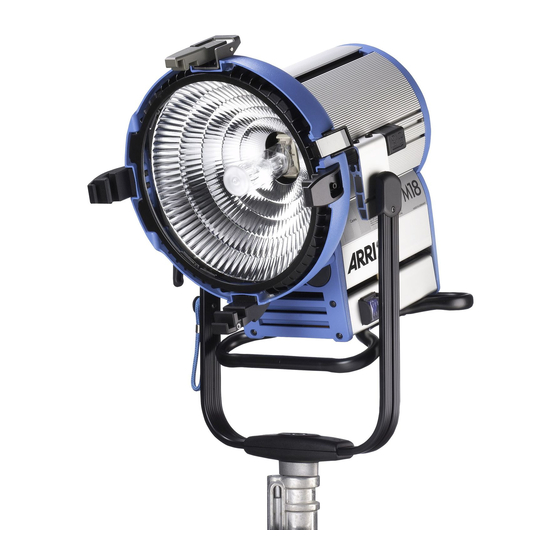
ARRI M18 Service Manual
Hide thumbs
Also See for M18:
- User manual (10 pages) ,
- Short instructions (6 pages) ,
- Short instructions (6 pages)
Table of Contents
Advertisement
Quick Links
Advertisement
Table of Contents

Related Manuals for ARRI M18


Summary of Contents for ARRI M18
- Page 1 S E R V I C E M A N U A L Date: February 7, 2019 Supported Models L1.37600.B...
-
Page 2: Table Of Contents
Lamphead Connector Cables ..................16 Stirrup ..........................17 Maintenance and Care ..................... 18 Visual Inspection ......................18 Cleaning ..........................18 Testing of mechanical components ................18 Contact ..........................19 Further Information ......................19 M18 – Service Manual Page 2 of 19... -
Page 3: Important Information
Please also refer to the Ordinance on Industrial Safety and Health as well as the relevant guidelines and regulations of your national Industrial Injuries Corporation (e.g. BGI 810-1, -3 and -4, BGV A1 for Germany; OSHA or ESTA for USA; etc.). Please refer also to our leaflet "Operating your ARRI Lamp heads safely" L5.70431.E... -
Page 4: Required Tools
» the application of safety extra low voltage, protective separation or protective insulation » equipotential bonding Required Tools Torx Screwdriver TX 20 Torx Screwdriver TX 15 Torx Screwdriver TX 10 Allen Key size 1.5mm Wrench size 5.5 M18 – Service Manual Page 4 of 19... -
Page 5: Disassembling Order
Make sure that the lamp head is fully disconnected from the mains and cooled down for a minimum of 30 minutes before opening the cover or beginning the repair. IMPORTANT NOTE: SEE SERVICE PARTS MANUAL FOR CORRECT VERSIONS OF PARTS AS PER SERIAL NUMBER M18 – Service Manual Page 5 of 19... -
Page 6: Lens Holder & Safety Glass
1 screw (Torx 10) on the safety switch activator pin. Note: Pay close attention to the position of the lens door springs. Note: Remember when ordering the glass there are two pieces of glass per lens door. M18 – Service Manual Page 6 of 19... - Page 7 Please ensure that all parts go back in the correct position. Tip: Old versions have no spacer plate between the lens door and the safety switch activator pin plate. Please follow the instructions in the safety switch activator section. M18 – Service Manual Page 7 of 19...
-
Page 8: Reflector
Reach into the reflector as pictured to avoid leaving finger prints on the inside of the reflector Note: This is an opportunity to clean the reflector with glass cleaner and a soft cloth. matte/dull reflectors must be replaced. M18 – Service Manual Page 8 of 19... -
Page 9: Safety Switch Activator & Door Latch (Ssa)
Loosen the worm screw with a 1.5 mm Allen Key, carefully! This can break easily. NOT remove, simply loosen until the safety switch activator is loose. The SSA can now be moved forwards or backwards. M18 – Service Manual Page 9 of 19... - Page 10 (movement) between the black lens door and the blue front housing. Tip: If the gap is too big then the safety loop can be opened and the lamphead will not strike. M18 – Service Manual Page 10 of 19...
- Page 11 Note: You can also measure the safety loop. Please see the wiring diagram. Important: If the door latch is not adjusted properly this affects the SSA function. M18 – Service Manual Page 11 of 19...
-
Page 12: Housing
Remove the screw (Torx 20) of the lamp lock knob. Loosen the screw and remove completely. Remove 4 housing screws (Torx 20.) Two from the front and two in the back as pictured. M18 – Service Manual Page 12 of 19... - Page 13 To remove the lamp holder, unscrew two screws (Torx 20) on the front side. Unscrew the HT cables and disconnect. Slide the complete lamp holder assembly to the front and remove it completely. M18 – Service Manual Page 13 of 19...
-
Page 14: Base Group & Ignitor
Loosen the 2 middle screws (marked in yellow.) Do not remove. Tip: Loosening the screws helps to get a bigger gap in the blue housing to remove the ignitor assembly. Pull out the electronic box towards you to remove. M18 – Service Manual Page 14 of 19... - Page 15 Tip: To reassemble loosen all 4 screws of the skid. This alows a better fit for the base group and the housing. Tip: After reassembling tighten screws! M18 – Service Manual Page 15 of 19...
-
Page 16: Lamphead Connector Cables
Lamphead Connector Cables Remove 2 screws (Torx 20.) Remove cover. Remove 2 screws as shown. Note: The wiring diagrams are only available to trained ARRI Service Technicians. M18 – Service Manual Page 16 of 19... -
Page 17: Stirrup
Remove two screws (Torx 15) from the internal baffle. Remove the front casting. Loosen 4 screws (Torx 20.) Two on each side on the brackets. Do not remove! Slide out the stirrup M18 – Service Manual Page 17 of 19... -
Page 18: Maintenance And Care
Burn marks or discoloration may be an indication for contact problems. We strongly recommend a replacement to avoid damage on the lamp head. Please contact your local ARRI service partner for more information about how to adjust the lamp socket correctly. -
Page 19: Contact
The manufacturer disclaims liability for any damage to persons or properties which are caused by an inappropriate operation of the fixture. Those lie in the responsibility of the operator. Visit our homepage www.arri.com/service-lighting for downloads and software tools. M18 – Service Manual...
Need help?
Do you have a question about the M18 and is the answer not in the manual?
Questions and answers