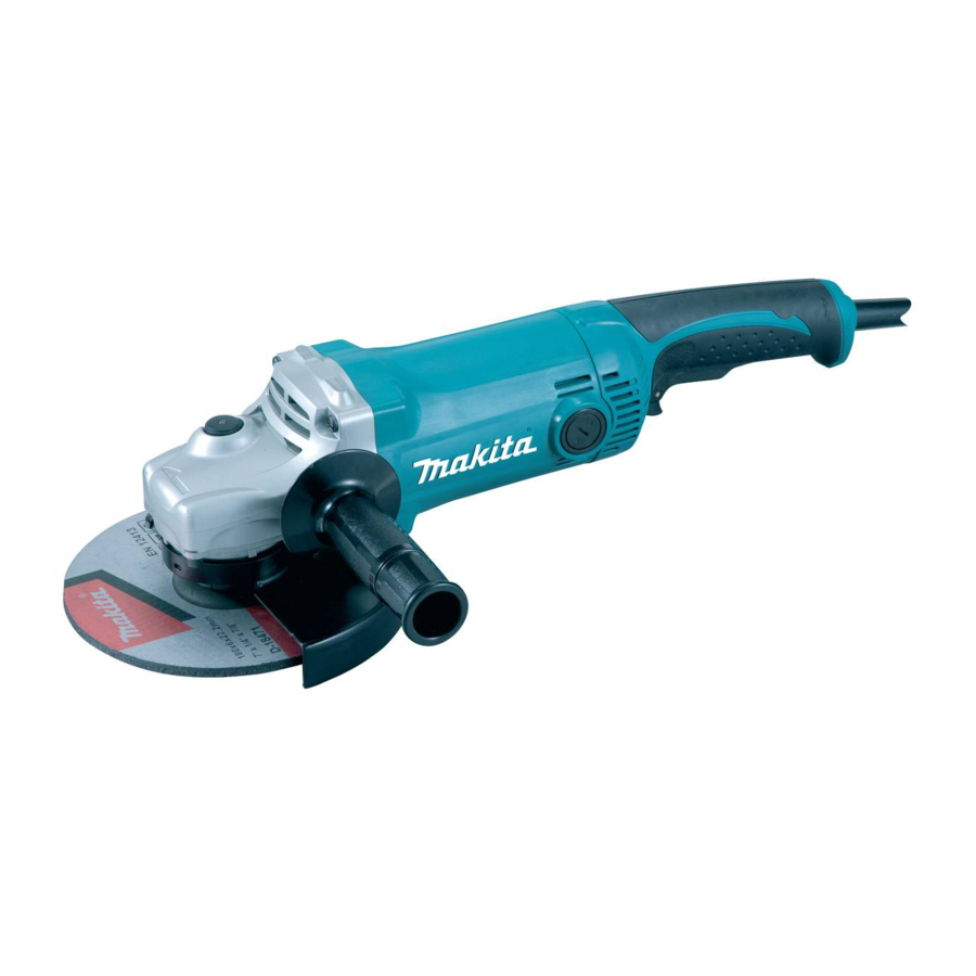
Makita GA7050 Technical Information
180mm 7" / 230mm 9"
Hide thumbs
Also See for GA7050:
- Instruction manual (104 pages) ,
- Instruction manual (17 pages) ,
- Instruction manual (80 pages)
Table of Contents
Advertisement
Quick Links
T
ECHNICAL INFORMATION
Model No.
Description
C
ONCEPT AND MAIN APPLICATIONS
Models GA7050 and GA9050 are developed as easy-to-control
2000W class angle grinder, featuring compact and lightweight
tool design achieved by employing:
Newly developed, compact and lightweight motor (Type S-82)
Down-sized gear housing and main handle
Especially in compactness, the products are unrivalled;
the overall length of 432 mm (17'') is the shortest among the 2000W
class models available in the global market as of February 2010.
Wheel size is:
180mm (7'') for Model GA7050
230mm (9'') for Model GA9050
S
pecification
Voltage (V)
110
120
220
230
240
Specification
Wheel size: mm (")
No load speed: min-
Soft start feature
Anti-restart function
Double insulation
Power supply cord: m (ft)
Net weight
: kg (lbs)
*3
*1 for Brazil, Australia
*2 for all countries except the two listed above
*3 Weight according to EPTA-Procedure 01/2003, with Side grip, Wheel cover, Inner flange, Lock nut
S
tandard equipment
Lock nut wrench 35 ......... 1
Side grip 36 ...................... 1
Note: The standard equipment for the tool shown above may vary by country.
O
ptional accessories
Vibration absorbing side grip
Toolless quick adjustable wheel cover
Toolless lock nut
Dust cover attachment
GA7050: Accessories for 180mm angle grinder
GA9050: Accessories for 230mm angle grinder
GA7050/ GA9050
Angle Grinders 180mm (7'')/ 230mm (9'')
Current (A)
Cycle (Hz)
19
50/ 60
15
50/ 60
9.6
50/ 60
9.2
50/ 60
8.8
50/ 60
Model No.
Diameter
Hole diameter
= rpm.
1
Continuous Rating (W)
Input
2,000
---
2,000
2,000
2,000
GA7050
180 (7)
22.23 (7/8)
8,500
No
No
Yes
2.0 (6.6)
/ 2.5 (8.2)
*1
4.5 (9.9)
L
H
W
Dimensions: mm (")
GA7050
Model No.
Length (L)
432 (17)
Width (W)
200 (7-7/8)
Height (H)
132 (5-3/16)
Max. Output (W)
Output
900
2,900
900
2,900
1,100
3,600
1,100
3,600
1,100
3,600
GA9050
230 (9)
6,600
*2
4.7 (10.4)
PRODUCT
P 1/ 8
GA9050
250 (9-7/8)
Advertisement
Table of Contents

Related Manuals for Makita GA7050


Summary of Contents for Makita GA7050
- Page 1 Description Angle Grinders 180mm (7'')/ 230mm (9'') ONCEPT AND MAIN APPLICATIONS Models GA7050 and GA9050 are developed as easy-to-control 2000W class angle grinder, featuring compact and lightweight tool design achieved by employing: Newly developed, compact and lightweight motor (Type S-82) Down-sized gear housing and main handle Dimensions: mm (")
- Page 2 V-block 1R269 Bearing extractor Assembling / Disassembling Ball bearings [2] LUBRICATIONS Apply Makita grease SG.No.0 to the following portions designated with the black triangle to protect parts and product from unusual abrasion. Item No. Description Portion to lubricate Gear housing complete Apply approx. 35g grease to Gear room.
- Page 3 P 3/ 8 epair [3] DISASSEMBLY/ASSEMBLY [3]-1. Armature, Spiral bevel gear (small), Ball bearing 6201DDW, Ball bearing 6000DDW DISASSEMBLING (1) Disassemble Armature assembly and Small spiral bevel gear as illustrated in Figs. 2 and 3. Fig. 2 Remove Carbon brushes. And then, Separate Gear housing complete Separate Bearing box from Gear remove four 5x35 Tapping screws.
- Page 4 P 4/ 8 epair [3] DISASSEMBLY/ASSEMBLY [3]-1. Armature, Spiral bevel gear (small), Ball bearing 6201DDW, Ball bearing 6000DDW (cont.) ASSEMBLING Assemble Gear housing section by setting Felt ring 16, Ball bearing 6201DDW and Retaining ring (INT) R-32 in place of Gear housing complete in accordance with the following steps.
- Page 5 P 5/ 8 epair [3] DISASSEMBLY/ASSEMBLY [3]-2. Large spiral bevel gear, Ball bearing 608ZZ, Ball bearing 6202DDW DISASSEMBLING (1) Large spiral bevel gear can be disassembled as illustrated in Figs. 9, 10R and 11. Fig. 9 Remove Bearing box from Remove Ball bearing 608ZZ with 1R269.
- Page 6 P 6/ 8 epair [3] DISASSEMBLY/ASSEMBLY [3]-2. Large spiral bevel gear, Ball bearing 608ZZ, Ball bearing 6202DDW (cont.) DISASSEMBLING (2) Ball bearing 6202DDW can be disassembled as illustrated in Fig. 12A or Fig. 12B. Fig. 12A Fig. 12B If it is difficult to remove as illustrated in Fig.
- Page 7 P 7/ 8 epair [3] DISASSEMBLY/ASSEMBLY [3]-3. Shaft lock mechanism DISASSEMBLING (1) Remove Gear housing complete from Motor housing. Remove Bearing box from Gear housing complete as illustrated in Fig. 2. (2) Remove Armature from Gear housing complete as illustrated in Fig. 3. (3) Shaft lock mechanism can be disassembled as illustrated in Figs.
- Page 8 P 8/ 8 ircuit diagram Fig. D-1 Color index of lead wires' sheath Black White Field viewed from Commutator side Brown lead wire is used for some countries. Blue lead wire is used Noise suppressor (if used) for some countries. iring diagram Fig.
Need help?
Do you have a question about the GA7050 and is the answer not in the manual?
Questions and answers