
Related Manuals for Emerson Bettis RTS CL Series


Summary of Contents for Emerson Bettis RTS CL Series
- Page 1 User Instructions MAN-02-04-60-0350-EN Rev. 3 February 2019 Operating Manual for Bettis RTS CL Series Compact Linear Electric Actuator...
-
Page 3: Table Of Contents
User Instructions Table of Contents MAN-02-04-60-0350-EN Rev. 3 February 2019 Table of Contents Section 1: Introduction Section 2: General Actuator Overview ..................3 Serial Number and Type Label ............... 5 Operating Mode .................... 5 Protection Class .................... 6 Mounting Position ..................6 Direction of Rotation .................. - Page 4 Table of Contents User Instructions February 2019 MAN-02-04-60-0350-EN Rev. 3 Section 7: Parameter Menu Parameter Group: End Limit ................ 38 Parameter Group: Torque ................40 Parameter Group: Speed ................41 Parameter Group: Ramp (option) ..............41 Parameter Group: Control ................42 Parameter Group: Password ................
- Page 5 User Instructions Table of Contents MAN-02-04-60-0350-EN Rev. 3 February 2019 Section 13: Fuses Section 14: Lubricant Recommendation and Requirements 14.1 Main Body: -25 to +60°C ................72 14.2 Output Type A and Spindle Drives (Linear Actuators) -40 to +85°C ....72 14.3 Basic Lubricant Service Interval ..............
-
Page 6: Section 1: Introduction
MAN-02-04-60-0350-EN Rev. 3 Section 1: Introduction These operating instructions apply to Bettis RTS CL Series of Compact Linear actuators. The scope of application covers the operation of industrial valves, e.g., globe valves, gate valves, butterfly valves and ball valves. For other applications please consult with the factory. -
Page 7: Section 2: General
User Instructions Section 2: General MAN-02-04-60-0350-EN Rev. 3 February 2019 Section 2: General Linear units are offered in three variants CL05, CL15, CL25. The linear adaptions are mounted to the Compact Multi-turn (CM) series to drive linear positioning movement. The linear unit converts the torque output from the actuator into an axial force. The combination of actuator and linear unit, is based on the required thrust and the necessary stroke. -
Page 8: Actuator Overview
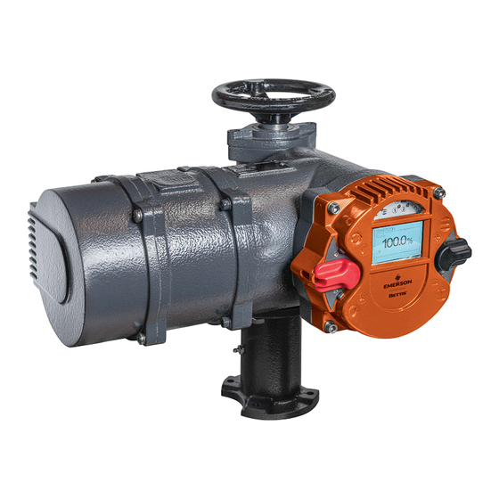
Section 2: General User Instructions February 2019 MAN-02-04-60-0350-EN Rev. 3 Actuator Overview Figure 1 The Bettis RTS Series Compact Linear Actuator Parts Overview: Handwheel Control unit (Operating unit) Connection compartment Gear component General... - Page 9 User Instructions Section 2: General MAN-02-04-60-0350-EN Rev. 3 February 2019 Figure 2 Parts Overview: Ring nut Axial bearing Spindle nut Axial bearing Output flange Centering ring Housing linear unit Spindle Bellows General...
-
Page 10: Serial Number And Type Label
(see Figure 3) of the actuator (the type label is located next to the handwheel – see Figure 4). Using this serial number, Emerson can uniquely identify the actuator (type, size, design, options, technical data and test report). Figure 3... -
Page 11: Protection Class
User Instructions Section 2: General MAN-02-04-60-0350-EN Rev. 3 February 2019 Protection Class RTS Compact Linear CL actuators come by default with IP 68 (EN 50629) protection. CAUTION: PROTECTION CLASS AND CABLE GLANDS The protection class specified on the type label is only effective when cable glands also pro- vide the required protection class, the cover of the connection compartment is carefully screwed and the mounting position (see Section 2.5) is observed. -
Page 12: Direction Of Rotation
Section 2: General User Instructions February 2019 MAN-02-04-60-0350-EN Rev. 3 Direction of Rotation Unless specifically ordered otherwise, the standard direction is (see Figure 5 and Figure 6): • Right turning (clockwise) = CLOSING • Left turning (counter clockwise) = OPENING Clockwise rotation of the actuator is given when the output shaft turns counter clockwise when looking on the output shaft. -
Page 13: Protection Devices
User Instructions Section 2: General MAN-02-04-60-0350-EN Rev. 3 February 2019 Protection Devices 2.7.1 Torque RTS Compact Linear actuators provide a electronic torque monitoring. The switch off torque can be modified in the menu of the controller for each direction separately. By default, switch off torque is set to the ordered value. If no torque was specified with the order, the actuator is supplied from the factory with the maximum configurable torque. -
Page 14: Delivery Condition Of The Actuators
Section 2: General User Instructions February 2019 MAN-02-04-60-0350-EN Rev. 3 Delivery Condition of the Actuators For each actuator, an inspection report is generated upon final inspection. In particular, this comprises a full visual inspection, calibration of the torque measurement in connection with an extensive run examination and a functional test of the micro controllers. -
Page 15: Section 3: Packaging, Transport And Storage
User Instructions Section 3: Packaging, Transport and Storage MAN-02-04-60-0350-EN Rev. 3 February 2019 Section 3: Packaging, Transport and Storage Depending on the order, actuators may be delivered packed or unpacked. Special packaging requirements must be specified when ordering. Please use extreme care when removing or repackaging equipment. -
Page 16: Long-Term Storage
Section 3: Packaging, Transport and Storage User Instructions February 2019 MAN-02-04-60-0350-EN Rev. 3 Long-term Storage CAUTION: 6 MONTHS OF STORAGE If you intend to store the actuator for over 6 months, also follow the instructions below: The silica gel in the connection compartment must be replaced after 6 months of storage (from date of delivery) After replacing the silica gel, brush the connection cover seal with glycerine. -
Page 17: Section 4: Assembly And Disassembly Of Linear Units On Valves
User Instructions Section 4: Installation Instructions MAN-02-04-60-0350-EN Rev. 3 February 2019 Section 4: Assembly and Disassembly of Linear Units on Valves In the following two subsections, the procedures for assembly and disassembly of linear units on valves are explained step by step. Security and Assembly Instructions CAUTION The device should be mounted and commissioned by qualified personnel. -
Page 18: Mechanical Connection
Section 4: Installation Instructions User Instructions February 2019 MAN-02-04-60-0350-EN Rev. 3 Mechanical Connection Check that the actuator flange, the linear unit flanges and the valve flange match. Thoroughly clean mounting surfaces and bare parts on actuator, linear unit and valve. Lightly grease the connections of the actuator, the linear unit and the valve. -
Page 19: Mounting Postion Of The Operating Unit
User Instructions Section 4: Installation Instructions MAN-02-04-60-0350-EN Rev. 3 February 2019 Mounting Postion of the Operating Unit The mounting postion of the operating unit can be rotated in 90° steps. Figure 8 Control System Mounting -90° +90° +180° • Disconnect the actuator and control system from the power supply. •... -
Page 20: Electrical Connection
(see name plate - Figure 3) The connection of electrical wiring must follow the circuit diagram. This can be found in the appendix of the documentation. The circuit diagram can be ordered from Emerson by specifying the serial number. - Page 21 User Instructions Section 4: Installation Instructions MAN-02-04-60-0350-EN Rev. 3 February 2019 4.5.1 Power Supply Connection RTS Compact Linear CL actuators feature an integrated motor controller, i.e. only a connection to the power supply is required. In non explosion-proof actuators, the wiring uses a connector independent from control signals (see Figure 9).
- Page 22 Section 4: Installation Instructions User Instructions February 2019 MAN-02-04-60-0350-EN Rev. 3 Figure 10 Bettis RTS Terminal Box Terminal Box Overview: Metric screw M40x1,5 2 x M20x1,5 M25x1,5 Terminals for the power supply Terminal for ground connection Outside ground connection Explosion-proof actuators or on special request the connection will be mady via terminals (see Figure 10).
-
Page 23: Section 5: Commisioning
User Instructions Section 5: Commissioning MAN-02-04-60-0350-EN Rev. 3 February 2019 Section 5: Commisioning Before commissioning, please ensure the actuator is correctly assembled and electrically connected. (see Section 4,). CAUTION: REMOVE SILICA GEL Remove silica gel from the connection compartment. General CAUTION: RESET ELECTRIC END POSITIONS During commissioning and after every disassembly of the actuator, the electric end posi- tions (see Section 5.4) must be reset. - Page 24 Section 5: Commissioning User Instructions February 2019 MAN-02-04-60-0350-EN Rev. 3 5.4.1 End limit OPEN Step 1 - Set the selector switch and control switch to the centre position. Figure 11 Switches in Center Position Terminal Box Overview: selector switch (red) control switch (black) Step 2 - Scroll through the menu with the control switch.
- Page 25 User Instructions Section 5: Commissioning MAN-02-04-60-0350-EN Rev. 3 February 2019 Step 3 - Afterwards, flip up the selector switch slightly and let it snap back to its neutral position. Figure 14 Selector Switch Setting (1) Figure 15 Selector Switch Setting (2) Figure 16 Selector Switch Setting (3) Commissioning...
- Page 26 Section 5: Commissioning User Instructions February 2019 MAN-02-04-60-0350-EN Rev. 3 Step 4 - This changes the bottom line of the display from "EDIT?" to "SAVE?" Figure 17 Edit and Save Figure 18 Save Settings Step 5 - Then, push down the selector switch until it snaps into place. In doing so, the bottom right now on the display will show "TEACHIN"...
- Page 27 User Instructions Section 5: Commissioning MAN-02-04-60-0350-EN Rev. 3 February 2019 Step 6 - Absolute and relative values on the display will change continuously along with position changes. Figure 19 Position Change Selector Setting Figure 20 Position Change Display Step 7 - Manually move the actuator with the handwheel (see Section 2.1, or 2.6) or by motor via the operating switch (black button) to the end position OPEN of the valve.
- Page 28 Section 5: Commissioning User Instructions February 2019 MAN-02-04-60-0350-EN Rev. 3 Display Overview: Absolute value, Relative value Step 8 - When the desired end position OPEN of the valve is reached, move the selector switch back to the middle position. Thus, the line "TEACHIN" disappears. Figure 22 Selector for End Position (Save) Figure 23...
- Page 29 User Instructions Section 5: Commissioning MAN-02-04-60-0350-EN Rev. 3 February 2019 Figure 25 Selector Setting Save (2) Figure 26 Selector Setting Save (3) Step 10 - This changes the bottom line of the display for "SAVE?" to "EDIT?" and the end position is stored.
-
Page 30: Final Step
Section 5: Commissioning User Instructions February 2019 MAN-02-04-60-0350-EN Rev. 3 Figure 28 Selector Setting Display (2) 5.4.2 End limit CLOSE Use menu item "P 1.2 End limit - End limit CLOSE" as for End limit OPEN Final Step Following commissioning, check for proper sealing the covers to be closed and cable inlets. (see Section 2.4) Check actuator for paint damage (by transport or installation) and repair if necessary. -
Page 31: Section 6: Control Unit
User Instructions Section 6: Control Unit MAN-02-04-60-0350-EN Rev. 3 February 2019 Section 6: Control Unit The controller is intended to monitor and control the actuator and provides the interface between the operator, the control system and the actuator. Operating Unit Operation relies on two switches: the control switch and a padlock-protected selector switch. -
Page 32: Display Elements
Section 6: Control Unit User Instructions February 2019 MAN-02-04-60-0350-EN Rev. 3 Display Elements 6.2.1 Graphic Display The graphic display used in the controller allows text display in different languages. Figure 30 Display (1) During operation, the displays shows the position of the actuator as a percentage, operation mode and status. - Page 33 User Instructions Section 6: Control Unit MAN-02-04-60-0350-EN Rev. 3 February 2019 6.2.2 LED Display To provide users with better status information, basic status data is displayed using 4-colour LEDs. As the device powers up, it undertakes a self-test whereby all 4 LEDs briefly lit up simultaneously.
-
Page 34: Operation
Section 6: Control Unit User Instructions February 2019 MAN-02-04-60-0350-EN Rev. 3 Operation The actuator is operated via the switches located on the controller (selection- and control switch). All actuator settings can be entered with these switches. Furthermore, configuration is also possible via the IR interface or the Bluetooth Interface (see Section 10). Flip the switch up or down to regulate the parameter menu scrolling speed. - Page 35 User Instructions Section 6: Control Unit MAN-02-04-60-0350-EN Rev. 3 February 2019 Figure 36 Full Switch Flip (Jump to the End of the Menu) 6.3.1 Operation mode Use the selector switch (red) to determine the various operating states of the actuator. In each of these positions, it is possible to block the switch by means of a padlock and thus protect the actuator against unauthorized access.
- Page 36 Section 6: Control Unit User Instructions February 2019 MAN-02-04-60-0350-EN Rev. 3 Depending on the selector switch position, the control switch performs different functions: Table 3. Control Switch Positions Position Function The control switch is used to scroll up or down the menu according to internal Selector switch symbolism.
- Page 37 User Instructions Section 6: Control Unit MAN-02-04-60-0350-EN Rev. 3 February 2019 Confirm the selector switch (with a slight flip towards , (see Figure 24, to Figure 28, ) to change the selected parameter. To confirm this input readiness, the display changes from "EDIT"...
- Page 38 Section 6: Control Unit User Instructions February 2019 MAN-02-04-60-0350-EN Rev. 3 Step 2 - Now, move the control switch down (towards ) until the menu item "P 20.6 Miscellaneous - Wireless" is displayed. Figure 40 Control Switch Flipped Down Figure 41 Display (1) Step 3 - Afterwards, flip up slightly the selector switch (towards ) and let it snap back to its neutral position.
- Page 39 User Instructions Section 6: Control Unit MAN-02-04-60-0350-EN Rev. 3 February 2019 Figure 43 Selector Switch Flipped Up Figure 44 Selector Switch in Neutral Position Step 4 - This changes the bottom line of the display from "EDIT?" to "SAVE?". Figure 45 Display (2) Control Unit...
- Page 40 Section 6: Control Unit User Instructions February 2019 MAN-02-04-60-0350-EN Rev. 3 Figure 46 Display (3) Step 5 - Flip up the control switch (toward ) to change the value from 0 (off) to 2 (Bluetooth). Figure 47 Control Switch Flipped Up Figure 48 Switch to One Control Unit...
- Page 41 User Instructions Section 6: Control Unit MAN-02-04-60-0350-EN Rev. 3 February 2019 Step 6 - If the value changes to 1, confirm the selection by flipping halfway up the selector switch (towards) and letting it snap back to its neutral position (see Figure 42 til Figure 46). Figure 49 Selector Switch Flipped Halfway Up Figure 50...
- Page 42 Section 6: Control Unit User Instructions February 2019 MAN-02-04-60-0350-EN Rev. 3 Figure 51 'Teachin' on Display CAUTION: MAXIMUM TORQUE MUST BE ALREADY SET Please note that, during motor operation, only torque monitoring remains active, as travel adjustment will happen subsequently. Therefore, please check beforehand whether the maximum torque has been already set.
-
Page 43: Section 7: Parameter Menu
User Instructions Section 7: Parameter Menu MAN-02-04-60-0350-EN Rev. 3 February 2019 Section 7: Parameter Menu For each parameter group, you can find a description tabular overview of the menu items and possible configurations. The parameter list below also includes all possible options per menu item. - Page 44 Section 7: Parameter Menu User Instructions February 2019 MAN-02-04-60-0350-EN Rev. 3 Table 4. End Limit Parameter Group Menu Menu Poss. Setting Notes / Comments Item Item The parameter value can be set using TEACHIN. With a known TEACHIN; P1.1 End limit Open travel, the second end position can be entered after setting 0 - 100U...
-
Page 45: Parameter Group: Torque
User Instructions Section 7: Parameter Menu MAN-02-04-60-0350-EN Rev. 3 February 2019 CAUTION: NOTE TRAVEL LIMITS When installing the actuator on an gear or a thrust unit, please take into account the limits and factors of the gear / thrust unit at parametrization. CAUTION: SET LIMITS CORRECTLY When using end limit switch off by torque, the end position limit must be set before reaching the torque limit. -
Page 46: Parameter Group: Speed
Section 7: Parameter Menu User Instructions February 2019 MAN-02-04-60-0350-EN Rev. 3 Parameter Group: Speed Table 6. Speed Parameter Group Sub Menu Poss. Menu item Notes / Comments item Setting 2,5 - P4.1 Speed Local Open Output speed for local operation in direction OPEN 72,2min −1 2,5 -... -
Page 47: Parameter Group: Control
User Instructions Section 7: Parameter Menu MAN-02-04-60-0350-EN Rev. 3 February 2019 Parameter Group: Control Table 8. Control Parameter Group Sub Menu Poss. Menu Item Notes / Comments Item Setting P6.2 Control Ready delay 0 - 10 sec. Drop-out delay for the ready signal (Binary outputs) 24V auxiliary output is deactivated (section 16.5) The function of the auxiliary input is still activated P6.5... -
Page 48: Parameter Group: Position
Section 7: Parameter Menu User Instructions February 2019 MAN-02-04-60-0350-EN Rev. 3 Parameter Group: Position In addition to OPEN and CLOSED end positions, you may define intermediate positions. These can be used as feedback signals for the binary outputs or as target value for fix position approach. - Page 49 User Instructions Section 7: Parameter Menu MAN-02-04-60-0350-EN Rev. 3 February 2019 Table 11. Binary Inputs Parameter Group (1) Menu Sub Menu Poss. Setting Notes / Comments Item Item 0:no function This input has no function OPEN command in REMOTE mode (selector switch in 1: Open position REMOTE).
- Page 50 Section 7: Parameter Menu User Instructions February 2019 MAN-02-04-60-0350-EN Rev. 3 Table 12. Binary Inputs Parameter Group (2) Menu Sub Menu Poss. Setting Notes / Comments Item Item Trigger lock CLOSED (in LOCAL and REMOTE mode). Actuator moves with the highest priority to CLOSED; 24: Lock Closed command continues internally active after reaching the end position CLOSED.
-
Page 51: Parameter Group: Binary Outputs
User Instructions Section 7: Parameter Menu MAN-02-04-60-0350-EN Rev. 3 February 2019 Parameter Group: Binary Outputs The controller is equipped with 8 freely configurable binary outputs. Please find further information on technical data of the binary outputs in Section 16.1. Provided with external supply, binary outputs are optically isolated from the rest of the controller. - Page 52 Section 7: Parameter Menu User Instructions February 2019 MAN-02-04-60-0350-EN Rev. 3 Table 14. Binary Outputs Parameter Group (2) Menu Sub Menu Poss. Setting Notes / Comments Item Item Remote operating mode (selector switch in position 22: Remote Remote) 23: Off Off operating mode (selector switch in the Off position) 24: No function No function...
- Page 53 User Instructions Section 7: Parameter Menu MAN-02-04-60-0350-EN Rev. 3 February 2019 Table 15. Binary Outputs Parameter Group (3) Menu Sub Menu Poss. Setting Notes / Comments Item Item Position = Intermediate position 2. The width of the 47: Pos.=Int2 interval is set with the parameter P8.6 Position = Intermediate position 3.
-
Page 54: Parameter Group: Position Output (Option)
Section 7: Parameter Menu User Instructions February 2019 MAN-02-04-60-0350-EN Rev. 3 CAUTION: NOTE SET TORQUE AND POSITION When using the point torque-dependent OPEN or torque-dependent CLOSED (see Section 7.1, Menu P1.3 u. P1.4) the actuator will only be open or closed when the set torque and the associated end position is reached. - Page 55 User Instructions Section 7: Parameter Menu MAN-02-04-60-0350-EN Rev. 3 February 2019 Table 17. Position Output Parameter Group (2) Sub Menu Poss. Menu item Notes / Comments Item Setting 0 - 20,5 P11.2 Position Output Start (at 0%) mA value for the Closed (0%) position mA {4mA} 0 - 20,5 mA P11.3...
-
Page 56: Parameter Group: Step Mode
Section 7: Parameter Menu User Instructions February 2019 MAN-02-04-60-0350-EN Rev. 3 7.11 Parameter Group: Step Mode Step mode operation can be used to extend the operating time in certain ranges or for the whole travel; it is available in local, remote and emergency mode. Step mode operation can be activated individually for the directions OPEN and CLOSED. - Page 57 User Instructions Section 7: Parameter Menu MAN-02-04-60-0350-EN Rev. 3 February 2019 Figure 52 Position Setting and Timing RATE RATE RATE RATE RATE RATE RATE RATE RATE RATE NOTE: It is important to ensure that the mode of operation is not exceeded! The running info on the actuator (see 6.2.2) only flashes while the drive is running, ie during the break, no flash.
-
Page 58: Parameter Group: Positioner (Option)
Section 7: Parameter Menu User Instructions February 2019 MAN-02-04-60-0350-EN Rev. 3 7.12 Parameter Group: Positioner (option) The positioner SR option is used to control the electric actuator by means of a set point input 0/4-20 mA signal. The SR helps control the position of the actuator, i.e. the positioner ensures that the actual value and thus the position of the actuator matches the desired set point. - Page 59 User Instructions Section 7: Parameter Menu MAN-02-04-60-0350-EN Rev. 3 February 2019 Table 20. Positioner Parameter Group (2) Sub Menu Poss. Menu Item Notes / Comments Item Setting Variable speed actuators (Bettis RTS CM and Smartcon CSC FU): Without function Fixed speed actuators (Smartcon CSC): This parameter is only relevant in Step P13.10 Positioner...
-
Page 60: Parameter Group: Pid Controller (Optional)
Section 7: Parameter Menu User Instructions February 2019 MAN-02-04-60-0350-EN Rev. 3 7.13 Parameter Group: PID Controller (optional) The optional PID controller is used for controlling an external actual value (process variable) to a setpoint using 0/4-20 mA signal by readjusting the actuator. Table 21. - Page 61 User Instructions Section 7: Parameter Menu MAN-02-04-60-0350-EN Rev. 3 February 2019 Table 22. PID Controller Parameter Group (2) Sub Menu Poss. Menu Item Notes / Comments Item Setting The monitoring of the external actual value is 0: Ignore disabled Actuator stops on signal failure of external. actual 1: Stop value On signal failure of external actual values, actuator...
-
Page 62: Parameter Group: Profibus-Dp (Option)
Section 7: Parameter Menu User Instructions February 2019 MAN-02-04-60-0350-EN Rev. 3 7.14 Parameter Group: Profibus-DP (option) PROFIBUS DP defines the technical and functional characteristics of a serial field bus system, which can be networked with distributed digital automation devices. PROFIBUS- DP is designed for the data exchange at the field level. -
Page 63: Parameter Group: Characteristic Curves (Optional)
User Instructions Section 7: Parameter Menu MAN-02-04-60-0350-EN Rev. 3 February 2019 7.16 Parameter Group: Characteristic Curves (optional) With this option, customers can enable travel-dependent torque characteristic curves. With these characteristic curves, torque limits already set under menu item P2 (torque), can be further re- duced depending on travel. -
Page 64: Parameter Group: Identification (Option)
Section 7: Parameter Menu User Instructions February 2019 MAN-02-04-60-0350-EN Rev. 3 7.17 Parameter Group: Identification (option) This option allows entering further custom-identification parameters Table 24. Identification Parameter Group Sub Menu Poss. Menu Item Notes / Comments Item Setting Used to enter a PPS number. This is displayed in the P18.1 Identification PPS number... - Page 65 User Instructions Section 7: Parameter Menu MAN-02-04-60-0350-EN Rev. 3 February 2019 Table 26. Miscellaneous Parameter Group (2) Sub Menu Poss. Menu Item Notes / Comments Item Setting no action P20.4 Miscellaneous Backup para By saving this setting, the currently set parameters 1: Custpara are adopted as customer parameters The fourth line of the display shows various...
-
Page 66: Section 8: Status Area
Section 8: Status Area User Instructions February 2019 MAN-02-04-60-0350-EN Rev. 3 Section 8: Status Area The status area presents current process and diagnostic data. There data is read-only. To access the status area, move the control switch in the direction where the selector switch should be in the neutral position or in the remote position. - Page 67 User Instructions Section 8: Status Area MAN-02-04-60-0350-EN Rev. 3 February 2019 Display Overview: Input Number Signal (0 = Low; 1 = High) 8.1.3 Status – Analogue values Display of analogue values: Input 1 (In1) is used by the positioner as the setpoint; Input 2 (In2) serves as an external value for the optional PID controler.
- Page 68 Section 8: Status Area User Instructions February 2019 MAN-02-04-60-0350-EN Rev. 3 8.1.5 Status – Firmware Figure 59 Firmware Status Display Display Overview: Firmware Firmware Date 8.1.6 Status – Serial number Figure 60 Serial Number Display Status Area...
-
Page 69: History
User Instructions Section 8: Status Area MAN-02-04-60-0350-EN Rev. 3 February 2019 Display Overview: Serial number of the control unit Serial number of the actuator Serial number of electronics 8.1.7 Status - meter readings Figure 61 Meter Readings Status Display Display Overview: Power-on Cycles Operating Hours Engine Duration... -
Page 70: Section 9: Infrared Connection
Section 9: Infrared Connection User Instructions February 2019 MAN-02-04-60-0350-EN Rev. 3 Section 9: Infrared Connection For easier communication and better visualization of the menu options, the unit provides an infrared port for connection to a PC. The required hardware (connection cable to the PC’s RS-232 or USB connectors) and the corresponding software are available as options. -
Page 71: Section 10: Bluetooth Link
User Instructions Section 10: Bluetooth Link MAN-02-04-60-0350-EN Rev. 3 February 2019 Section 10: Bluetooth Link In addition to the infrared interface, it is also possible to configure the Control System using a Bluetooth interface. Software required for Android equipment is available as an option. In addition to communication with the actuator, the Android software also enables management of multiple actuators, allowing easy transfer of parameter sets to various actuators. -
Page 72: Section 11: Maintenance
Section 11: Maintenance User Instructions February 2019 MAN-02-04-60-0350-EN Rev. 3 Section 11: Maintenance Maintenance work on open actuators may only be conducted if these are de-energized. Reconnection during maintenance is strictly prohibited. NOTE: Work on the electrical system or equipment must be carried out only in accordance with electrical regulations by a qualified electrician himself or by specially instructed personnel under the control and supervision of a qualified electrician. -
Page 73: Service/Exchange Of Spindel Nut And Axial Bearing
User Instructions Section 11: Maintenance MAN-02-04-60-0350-EN Rev. 3 February 2019 11.1 Service/Exchange of Spindel Nut and Axial Bearing This service must be performed at regular intervals, depending on the operating mode: Modulating operating mode: 5 years Open/Close operating mode: 10 years The following procedure is to be observed. -
Page 74: Section 12: Troubleshooting
Section 12: Troubleshooting User Instructions February 2019 MAN-02-04-60-0350-EN Rev. 3 Section 12: Troubleshooting Upon warning or error, the bottom line of the display will show the corresponding, plain text description. This event will also be entered into the history (see Section 8.2) 12.1 Error List Each error has a unique error number. - Page 75 User Instructions Section 12: Troubleshooting MAN-02-04-60-0350-EN Rev. 3 February 2019 Table 28. Errors and Indication (2) Error LED indicators Description #34: Internal Comm. Communication error between Display and Logik, cable D> error L4 is off broken between boards, boards defect, or firmware #35: Internal Comm.
-
Page 76: Section 13: Fuses
Section 13: Fuses User Instructions February 2019 MAN-02-04-60-0350-EN Rev. 3 Section 13: Fuses The logic board of the controller cover (see Figure 63) features two miniature fuses for the control lines. Figure 63 Fuse Location Display Overview: Fuse F10a for the binary outputs Fuse F10b fuse for auxiliary supply Table 30. -
Page 77: Section 14: Lubricant Recommendation And Requirements
User Instructions Section 14: Lubricant Recommendation and Requirements MAN-02-04-60-0350-EN Rev. 3 February 2019 Section 14: Lubricant Recommendation and Requirements 14.1 Main Body: -25 to +60°C Operating oil: DIN 51 517-CLP-HC i.e. fully synthetic high-performance gear oils based on poly-alpfa-olefins (PAO) •... - Page 78 Section 14: Lubricant Recommendation and Requirements User Instructions February 2019 MAN-02-04-60-0350-EN Rev. 3 Application example: Extremely low DT + extremely low ambient temperature + high speed + 87% utilization => 0,8 x 0,9 x 0,8 x 0,9 =0,51 reduction factor Lubrication maintenance interval =>...
-
Page 79: Section 15: Training
If you experience problems during installation or upon adjustments on site, please contact Emerson, Texas at +1 281 477 4100 or to prevent any operational errors or damage to the actuators. Emerson recommends engaging only qualified personnel for installation of RTS CL Comapct Series actuators. -
Page 80: Section 16: Technical Data And Certifications
Section 16: Technical Data and Certifications User Instructions February 2019 MAN-02-04-60-0350-EN Rev. 3 Section 16: Technical Data and Certifications 16.1 Binary Outputs Figure 64 Control Unit Figure 65 Logic Board Technical Data and Certifications... -
Page 81: Binary Inputs
User Instructions Section 16: Technical Data and Certifications MAN-02-04-60-0350-EN Rev. 3 February 2019 Table 32. Binary Outputs Characteristic Value Count 24VDC nominal range: 11. . . 35VDC Power supply (either from internal or external) Max voltage drop at set output Output voltage at non-set output <1 V Maximum current per output:... - Page 82 Section 16: Technical Data and Certifications User Instructions February 2019 MAN-02-04-60-0350-EN Rev. 3 Jumpers JP1 . . . JP3 can be used to interconnect the binary inputs to groups with separate earths: Figure 67 5 Inputs with Same Common Figure 68 2 Separated Groups of 2 Inputs with Same Ground Input IN3 is Disabled.
- Page 83 User Instructions Section 16: Technical Data and Certifications MAN-02-04-60-0350-EN Rev. 3 February 2019 Figure 70 3 Inputs with Same Common and 1 Separated Input. Input IN4 is Disabled. Figure 71 1 Separated Input and 3 Inputs with Same Common. Input IN2 is Disabled. Figure 72 5 inputs with common = "-"...
- Page 84 Section 16: Technical Data and Certifications User Instructions February 2019 MAN-02-04-60-0350-EN Rev. 3 Figure 73 5 inputs with common = "-" using internal 24V (e.g. for dry contacts) Figure 74 3 separated inputs using 3 separated external 24V Figure 75 3 separated inputs using 3 separated external 24V Technical Data and Certifications...
-
Page 85: Analogue Inputs
User Instructions Section 16: Technical Data and Certifications MAN-02-04-60-0350-EN Rev. 3 February 2019 16.3 Analogue Inputs Table 34. Input 1: Setpoint Value Characteristic Value Current range: 0-25mA Resolution: 14Bit Accuracy: 0,5% Input resistance: 60 Ohm Analog input 1 is electrically isolated from the rest of the electronic system. Table 35. - Page 86 Section 16: Technical Data and Certifications User Instructions February 2019 MAN-02-04-60-0350-EN Rev. 3 The analog output is galvanically isolated from the rest of the electronic system. Jumper JP4 can be used to switch the analog output from an active power source (default) to a current sink, allowing the output to simulate a 4.
-
Page 87: Auxiliary Voltage Input And Output
User Instructions Section 16: Technical Data and Certifications MAN-02-04-60-0350-EN Rev. 3 February 2019 16.5 Auxiliary Voltage Input and Output Table 37. Auxiliary voltage input and output Characteristic Value Input voltage range (auxiliary voltage input) 20. . . 30VDC Maximum current consumption 500mA (auxiliary voltage input) Maximum current consumption in power-save... -
Page 88: Connections
Section 16: Technical Data and Certifications User Instructions February 2019 MAN-02-04-60-0350-EN Rev. 3 16.6 Connections 16.6.1 Connections for non explosion-proof version Table 38. Non-explosionproof Connections Connection Value Industrial plug with 6 pins Screw connection Power/motor: 16A, max. 2,5mm2 , AWG14 Industrial plug with 24 pins Control signals Screw connection... - Page 89 User Instructions Section 16: Technical Data and Certifications MAN-02-04-60-0350-EN Rev. 3 February 2019 TYPE CL-05 CL-15 CL-25 Max Thrust (Adjustable) lbs. (kN) 3327 (15) 3327 (15) 5620 (25) Max Modulating Force lbs. (kN) 1798 (8) 1798 (8) 3327 (15) Adjustable Positioning Speed mm / sec 0.17 - 4.7 0.17 - 4.7...
- Page 91 Tianjin 301700 Holland Fasor 6 P. R. China Székesfehérvár 8000 The Emerson logo is a trademark and service mark of Emerson Electric Co. T +86 22 8212 3300 Hungary Bettis is a mark of one of the Emerson family of companies.
Need help?
Do you have a question about the Bettis RTS CL Series and is the answer not in the manual?
Questions and answers