
Related Manuals for Emerson Bettis RTS FL Series


Summary of Contents for Emerson Bettis RTS FL Series
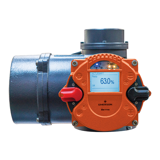
- Page 1 User Instructions MAN-02-04-60-0352-EN Rev. 3 February 2019 Operating Manual for Bettis RTS FL Series Fail-Safe Linear Electric Actuator...
-
Page 3: Table Of Contents
User Instructions Table of Contents MAN-02-04-60-0352-EN Rev. 3 February 2019 Table of Contents Section 1: Introduction Section 2: Functional Description of the RTS FL Fail-Safe Linear Actuator Fail-Safe Direction ..................3 Option Manual Override ................3 Section 3: General Information Safety Instructions .................. - Page 4 Table of Contents User Instructions February 2019 MAN-02-04-60-0352-EN Rev. 3 Section 7: Control Unit Operating Unit .................... 31 Display Elements ..................32 Operation ....................34 Section 8: Parameter Menu Parameter Group: End Limit ................ 43 Parameter Group: Torque ................45 Parameter Group: Speed ................
- Page 5 User Instructions Table of Contents MAN-02-04-60-0352-EN Rev. 3 February 2019 Section 14: Fuses Section 15: Lubricant Recommendations and Requirements 15.1 Main Body: -25 C to +60 C ................76 15.2 Main Body: -40 C to +60 C ................76 15.3 Output type A and spindle drives (Linear Actuators) -40 to +60C ....
-
Page 6: Section 1: Introduction
Section 1: Introduction User Instructions February 2019 MAN-02-04-60-0352-EN Rev. 3 Section 1: Introduction Bettis RTS FL Fail-Safe electric actuators are designed to operate appropriate valves when a fail-safe functionality is required. Appropriate valves are all kind of valves that require a linear movement to operate (globe valve, gate valves, etc.). -
Page 7: Section 2: Functional Description Of The Rts Fl Fail-Safe Linear Actuator
User Instructions Section 2: Functional Description of the RTS FL Fail-Safe Linear Actuator MAN-02-04-60-0352-EN Rev. 3 February 2019 Section 2: Functional Description of the RTS FL Fail-Safe Linear Actuator In normal operation, the actuator is operated by a PM motor (1). Via a worm gear stage (2) and a planetary gear train (3), the motor drives the spindle nut of a ball screw (4). -
Page 8: Fail-Safe Direction
Section 2: Functional Description of the RTS FL Fail-Safe Linear Actuator User Instructions February 2019 MAN-02-04-60-0352-EN Rev. 3 Parts Overview: Motor Worm Gear Stage Planetary Gear Train Ball Screw Operating Current Brake Spring Packet Spring Loaded Spindle Pin Valve Stem Fail-Safe Direction This type of fail-safe actuator can be built in two versions for "Fail-Safe Close"... - Page 9 User Instructions Section 2: Functional Description of the RTS FL Fail-Safe Linear Actuator MAN-02-04-60-0352-EN Rev. 3 February 2019 Figure 3 RTS FL Fail-Safe Linear Actuator with Padlock Parts Overview: Handwheel Coupling Rod Padlock Functional Description of the RTS FL Fail-Safe Linear Actuator...
-
Page 10: Section 3: General Information
(see Figure 4) of the actuator (the type label is located next to the handwheel – see Figure 5). Using this serial number, Emerson can uniquely identify the actuator (type, size, design, options, technical data and test report). -
Page 11: Operating Mode
User Instructions Section 3: General Information MAN-02-04-60-0352-EN Rev. 3 February 2019 Figure 5 Label 1 - Type Label Operating Mode RTS Fail-Safe Linear FL actuators are suitable for open-loop control (S2 operating mode - on/off duty) and closed-loop control (S9 operating mode - modulating duty) according to EN 60034-1. -
Page 12: Mounting Position
Section 3: General Information User Instructions February 2019 MAN-02-04-60-0352-EN Rev. 3 Mounting Position Generally, the installation position is irrelevant. However, based on practical experience, it is advisable to consider the following for outdoors use or in splash zones: • Mount actuators with cable inlet facing downwards •... -
Page 13: Protection Devices
User Instructions Section 3: General Information MAN-02-04-60-0352-EN Rev. 3 February 2019 CAUTION: OBSERVE DIRECTION OF ROTATION All specifications in this operating manual refer to the standard direction of rotation. Protection Devices 3.7.1 Torque RTS Fail-Safe Linear FL actuators provide electronic torque monitoring. The switch off torque can be modified in the menu of the controller for each direction separately. -
Page 14: Information Notice (Tag)
Section 3: General Information User Instructions February 2019 MAN-02-04-60-0352-EN Rev. 3 CAUTION: OBSERVE COMMISSIONING INSTRUCTIONS Commissioning instructions (see Section 5) must be strictly observed. During assembly of the supplied valves at the factory, end postions are set and documented by attaching a label (see Figure 8). -
Page 15: Section 4: Packaging, Transport And Storage
User Instructions Section 4: Packaging, Transport and Storage MAN-02-04-60-0352-EN Rev. 3 February 2019 Section 4: Packaging, Transport and Storage Depending on the order, actuators may be delivered packed or unpacked. Special packaging requirements must be specified when ordering. Please use extreme care when removing or repackaging equipment. -
Page 16: Long-Term Storage
Section 4: Packaging, Transport and Storage User Instructions February 2019 MAN-02-04-60-0352-EN Rev. 3 Long-term Storage CAUTION: 6 MONTHS OF STORAGE If you intend to store the actuator for over 6 months, also follow the instructions below: The silica gel in the connection compartment must be replaced after 6 months of storage (from date of delivery) After replacing the silica gel, brush the connection cover seal with glycerine. -
Page 17: Section 5: Installation Instructions
User Instructions Section 5: Installation Instructions MAN-02-04-60-0352-EN Rev. 3 February 2019 Section 5: Installation Instructions Installation work of any kind of actuator may only be performed by qualified personnel. Mechanical Connection Check: • Whether valve flange and actuator base match-up. •... -
Page 18: Mounting Of Linear Fail-Safe Actuator
Valve or piping may be damaged due to high actuating speed. Mounting of Linear Fail-Safe Actuator Emerson Bettis RTS FL Fail-Safe Linear electric actuators move the stem of valve to the failsafe position in case of failsafe event. In general stem of actuator is at failsafe position at... - Page 19 User Instructions Section 5: Installation Instructions MAN-02-04-60-0352-EN Rev. 3 February 2019 Figure 9 Linear Fail-Safe (1) 5.2.2 Mounting procedure for valve with required sealing force: • Connect mounting kit to valve and fix according valve producer specification • Be sure stem of valve is exact in desired failsafe end position •...
- Page 20 Section 5: Installation Instructions User Instructions February 2019 MAN-02-04-60-0352-EN Rev. 3 5.2.3 Alternative procedure for valve with required sealing force: • Connect mounting kit to valve and fix according valve producer specification • Be sure stem of valve is exact in desired failsafe end position •...
-
Page 21: Mounting Position Of The Operating Unit
User Instructions Section 5: Installation Instructions MAN-02-04-60-0352-EN Rev. 3 February 2019 Mounting Position of the Operating Unit The mounting position of the operating unit can be rotated in 90 steps. Figure 11 RTS FL Fail-Safe Control Unit -90° +90° +180° •... -
Page 22: Electrical Connection
(see name plate - Figure 4) The connection of electrical wiring must follow the circuit diagram. This can be found in the appendix of the documentation. The circuit diagram can be ordered from Emerson by specifying the serial number. - Page 23 User Instructions Section 5: Installation Instructions MAN-02-04-60-0352-EN Rev. 3 February 2019 5.4.1 Power Supply Connection RTS Fail-Safe Linear FL actuators feature an integrated motor controller, i.e. only a connection to the power supply is required. In non explosion-proof actuators, the wiring uses a connector independent from control signals (see Figure 12).
- Page 24 Section 5: Installation Instructions User Instructions February 2019 MAN-02-04-60-0352-EN Rev. 3 Explosion-proof actuators or on special request the connection will be made via terminals (see Figure 13). Figure 13 Bettis RTS Terminal Box Terminal Box Overview: Metric screw M40x1,5 2 x M20x1,5 M25x1,5 Terminals for the power supply Terminal for ground connection...
-
Page 25: Section 6: Commissioning
User Instructions Section 6: Commissioning MAN-02-04-60-0352-EN Rev. 3 February 2019 Section 6: Commissioning It is assumed that the actuator has been installed and electrically connected correctly. (See Section 5). NOTE: Remove silica gel from the alarm cover. General Information NOTE: When commissioning and each time after dismounting the actuator, the positions have to be reset (see Section 6.4). -
Page 26: Mechanical Default Settings And Preparation
Section 6: Commissioning User Instructions February 2019 MAN-02-04-60-0352-EN Rev. 3 Figure 14 RTS FL Fail-Safe Actuator Handwheel Rotation Parts Overview: • Handwheel • Coupling Rod • Padlock Handwheel Rotation: • Handwheel clockwise rotation = Retract the actuator stem • Handwheel counterclockwise rotation = Extend actuator stem To exit the manual mode and enable the actuator again for the automatic mode ensure that: •... -
Page 27: End Limit Setting
User Instructions Section 6: Commissioning MAN-02-04-60-0352-EN Rev. 3 February 2019 End Limit Setting A detailed description of the operation of the RTS Fail-Safe Linear FL controller can be found in Section 7.2. 6.4.1 End limit OPEN Step 1 - Set the selector switch and control switch to the centre position. Figure 15 Switches in Center Position Terminal Box Overview:... - Page 28 Section 6: Commissioning User Instructions February 2019 MAN-02-04-60-0352-EN Rev. 3 Figure 17 Front Display for End Limit Open Step 3 - Afterwards, flip up the selector switch slightly and let it snap back to its neutral position. Figure 18 Selector Switch Setting (1) Figure 19 Selector Switch Setting (2) Commissioning...
- Page 29 User Instructions Section 6: Commissioning MAN-02-04-60-0352-EN Rev. 3 February 2019 Figure 20 Selector Switch Setting (3) Step 4 - This changes the bottom line of the display from "EDIT?" to "SAVE?" Figure 21 Edit and Save Figure 22 Save Settings Step 5 - Then, push down the selector switch until it snaps into place.
- Page 30 Section 6: Commissioning User Instructions February 2019 MAN-02-04-60-0352-EN Rev. 3 CAUTION: CHECK MAXIMUM PARAMETERIZED TORQUE Please note that, during motor operation, only torque monitoring remains active, as travel ad justment will happen subsequently. Therefore, please check beforehand whether the maximum torque has been already parameterised. Step 6 - Absolute and relative values on the display will change continuously along with position changes.
- Page 31 User Instructions Section 6: Commissioning MAN-02-04-60-0352-EN Rev. 3 February 2019 Figure 25 Absolute Value Display Overview: Absolute value Step 8 - When the desired end position OPEN of the valve is reached, move the selector switch back to the middle position. Thus, the line "TEACHIN" disappears. Figure 26 Selector for End Position (Save) Figure 27...
- Page 32 Section 6: Commissioning User Instructions February 2019 MAN-02-04-60-0352-EN Rev. 3 Step 9 - In order to confirm the end position (save), slightly flip up the selector switch towards and let it snap back to its neutral position. Figure 28 Selector Setting Save (1) Figure 29 Selector Setting Save (2) Figure 30...
-
Page 33: Adjusting Of Fail-Safe Speed
User Instructions Section 6: Commissioning MAN-02-04-60-0352-EN Rev. 3 February 2019 Step 10 - This changes the bottom line of the display for "SAVE?" to "EDIT?" and the end position is stored. Figure 31 Selector Setting Display (1) Figure 32 Selector Setting Display (2) 6.4.2 End limit CLOSE Repeat 5.4.1 but select "P 1.2 End limit - End limit CLOSE". - Page 34 Section 6: Commissioning User Instructions February 2019 MAN-02-04-60-0352-EN Rev. 3 6.5.1 Setting Procedure CAUTION: NO POWERING UP DURING MAINTENANCE All adjustment work may only be performed with the actuator disconnected from the power supply. Due to this requirement, the actuator has to be in the fail-safe position. Any powering up must be ruled out during maintenance.
-
Page 35: Final Step
User Instructions Section 6: Commissioning MAN-02-04-60-0352-EN Rev. 3 February 2019 Loosen but do not remove 4pcs of screws according Figure 8. Insert 3mm allen key into radial borehole of flange. Turn flange by use of allen key in direction according Figure 8. Half of possible rotating angle will approximately double failsafe speed of actuator. -
Page 36: Section 7: Control Unit
Section 7: Control Unit User Instructions February 2019 MAN-02-04-60-0352-EN Rev. 3 Section 7: Control Unit The controller is intended to monitor and control the actuator and provides the interface between the operator, the control system and the actuator. Operating Unit Operation relies on two switches: the control switch and a padlock-protected selector switch. -
Page 37: Display Elements
User Instructions Section 7: Control Unit MAN-02-04-60-0352-EN Rev. 3 February 2019 Display Elements 7.2.1 Graphic Display The graphic display used in the controller allows text display in different languages. Figure 36 Display (1) During operation, the displays shows the position of the actuator as a percentage, operation mode and status. - Page 38 Section 7: Control Unit User Instructions February 2019 MAN-02-04-60-0352-EN Rev. 3 7.2.2 LED Display To provide users with better status information, basic status data is displayed using 4 color LEDs. As the device powers up, it undertakes a self-test whereby all 4 LEDs briefly lit up simultaneously.
-
Page 39: Operation
User Instructions Section 7: Control Unit MAN-02-04-60-0352-EN Rev. 3 February 2019 Operation The actuator is operated via the switches located on the controller (selection and control switch). All actuator settings can be entered with these switches. Furthermore, configuration is also possible via the IR interface or the Bluetooth Interface (see Section 11). Flip the switch up or down to regulate the parameter menu scrolling speed. - Page 40 Section 7: Control Unit User Instructions February 2019 MAN-02-04-60-0352-EN Rev. 3 Figure 42 Full Switch Flip (Jump to the End of the Menu) 7.3.1 Operation mode Use the selector switch (red) to determine the various operating states of the actuator. In each of these positions, it is possible to block the switch by means of a padlock and thus protect the actuator against unauthorized access.
- Page 41 User Instructions Section 7: Control Unit MAN-02-04-60-0352-EN Rev. 3 February 2019 Depending on the selector switch position, the control switch performs different functions: Table 4. Control Switch Positions Position Function The control switch is used to scroll up or down through the menu according to Selector switch internal symbolism.
- Page 42 Section 7: Control Unit User Instructions February 2019 MAN-02-04-60-0352-EN Rev. 3 Confirm the selector switch (with a slight flip upwards, towards , (see Figure 28, to Figure 32) to change the selected parameter. To confirm this input readiness, the display changes from "EDIT"...
- Page 43 User Instructions Section 7: Control Unit MAN-02-04-60-0352-EN Rev. 3 February 2019 Figure 46 Control Switch Flipped Down Figure 47 Display (1) Step 3 - Afterwards, flip up slightly the selector switch (towards ) and let it snap back to its neutral position: Figure 48 Selector Switch in Neutral Position...
- Page 44 Section 7: Control Unit User Instructions February 2019 MAN-02-04-60-0352-EN Rev. 3 Figure 49 Selector Switch Flipped Up Figure 50 Selector Switch in Neutral Position Step 4 - This changes the bottom line of the display from "EDIT?" to "SAVE?". Figure 51 Display (2) Control Unit...
- Page 45 User Instructions Section 7: Control Unit MAN-02-04-60-0352-EN Rev. 3 February 2019 Figure 52 Display (3) Step 5 - Flip up the control switch (toward ) to change the value from 0 (off) to 2 (Bluetooth). Figure 53 Control Switch Flipped Up Figure 54 Switch to One Control Unit...
- Page 46 Section 7: Control Unit User Instructions February 2019 MAN-02-04-60-0352-EN Rev. 3 Step 6 - If the value changes to 1, confirm the selection by flipping halfway up the selector switch (towards) and letting it snap back to its neutral position (see Figure 42 to Figure 46). Figure 55 Selector Switch Flipped Halfway Up Figure 56...
- Page 47 User Instructions Section 7: Control Unit MAN-02-04-60-0352-EN Rev. 3 February 2019 Figure 57 'Teachin' on Display CAUTION: MAXIMUM TORQUE MUST BE ALREADY SET Please note that, during motor operation, only torque monitoring remains active, as travel ad- justment will happen subsequently. Therefore, please check beforehand whether the maximum torque has been already set.
-
Page 48: Section 8: Parameter Menu
Section 8: Parameter Menu User Instructions February 2019 MAN-02-04-60-0352-EN Rev. 3 Section 8: Parameter Menu For each parameter group, you can find a description, tabular overview of the menu items and possible configurations. The parameter list below also includes all possible options per menu item. - Page 49 User Instructions Section 8: Parameter Menu MAN-02-04-60-0352-EN Rev. 3 February 2019 Table 6. End Limit Table (2) Menu Sub Menu Position Notes /Comments Item Item Setting The actuator uses end position signals to switch off and by travel (0) report the end position. The actuator signals the end position or stops the motor only after reaching the specified torque with the provision by torque (1)
-
Page 50: Parameter Group: Torque
Section 8: Parameter Menu User Instructions February 2019 MAN-02-04-60-0352-EN Rev. 3 Parameter Group: Torque If no torque was specified with the order, the actuator is supplied from the factory with the maximum configurable torque. Table 7. Torque Table Sub Menu Position Menu Item Notes/Comments... -
Page 51: Parameter Group: Speed
User Instructions Section 8: Parameter Menu MAN-02-04-60-0352-EN Rev. 3 February 2019 Parameter Group: Speed Table 8. Speed Table Sub Menu Position Menu Item Notes/Comments Item Setting P4.1 Speed Local Open 2.5. . . 72.2 rpm Output speed for local operation in direction OPEN P4.2 Speed Local Close... -
Page 52: Parameter Group: Control
Section 8: Parameter Menu User Instructions February 2019 MAN-02-04-60-0352-EN Rev. 3 Parameter Group: Control Table 10. Control Table Sub Menu Position Menu Item Notes/Comments Item Setting P6.2 Control Ready delay 0 - 10s Drop-out delay for the ready signal (Binary outputs) 24V auxiliary output is deactivated (see Section 17.5). -
Page 53: Parameter Group: Position
User Instructions Section 8: Parameter Menu MAN-02-04-60-0352-EN Rev. 3 February 2019 Parameter Group: Position In addition to OPEN and CLOSED end positions, you can define intermediate positions. These can be used as feedback signals for the binary outputs or as target value for fix position approach. -
Page 54: Parameter Group: Binary Inputs
Section 8: Parameter Menu User Instructions February 2019 MAN-02-04-60-0352-EN Rev. 3 Parameter Group: Binary Inputs The controller is equipped with 5 freely configurable binary inputs. Please find further information on technical data of the binary inputs in Section 17.2. Binary inputs are also effective during actuator control via Profibus (option). - Page 55 User Instructions Section 8: Parameter Menu MAN-02-04-60-0352-EN Rev. 3 February 2019 Table 14. Binary Inputs Table (2) Menu Sub Menu Position Notes/Comments Item Item Setting 14: Stop inv. As STOP but active low. 15: Open As Open Self-Hold but active low. Self-Hold inv.
- Page 56 Section 8: Parameter Menu User Instructions February 2019 MAN-02-04-60-0352-EN Rev. 3 Table 15. Binary Inputs Table (3) Menu Sub Menu Position Notes/Comments Item Item Setting 32: Intermediate As intermediate position 1 but with higher priority than position 2 intermediate positions 3 and 4. 33: Intermediate As intermediate position 1 but with higher priority than position 3...
-
Page 57: Parameter Group: Binary Outputs
User Instructions Section 8: Parameter Menu MAN-02-04-60-0352-EN Rev. 3 February 2019 Parameter Group: Binary Outputs The controller is equipped with 8 freely configurable binary outputs. Please find further information on technical data of the binary outputs in Section 28.1. Provided with external supply, binary outputs are optically isolated from the rest of the controller. - Page 58 Section 8: Parameter Menu User Instructions February 2019 MAN-02-04-60-0352-EN Rev. 3 Table 17. Binary Outputs Table (2) Menu Sub Menu Position Notes/Comments Item Item Setting 16: Position < Position < Intermediate position 2 Int.2 17: Position < Position > Intermediate position 3 Int.3 18: Position <...
- Page 59 User Instructions Section 8: Parameter Menu MAN-02-04-60-0352-EN Rev. 3 February 2019 Table 18. Binary Outputs Table (3) Menu Sub Menu Position Notes/Comments Item Item Setting 40: Fail-safe Fail-safe OK (only for fail-safe actuators) OK 1 41: Fail-safe Fail-safe OK and Ready (only for fail-safe actuators) OK 2 42: Fail-safe Fail-safe OK, Ready and Remote...
- Page 60 Section 8: Parameter Menu User Instructions February 2019 MAN-02-04-60-0352-EN Rev. 3 Table 19. Binary Outputs Table (4) Menu Sub Menu Position Notes/Comments Item Item Setting Output 1 is set to normal, i.e., if the condition in Normal point P10.1 is met, Output 1 is set to HIGH (active HIGH).
-
Page 61: Parameter Group: Position Output (Optional)
User Instructions Section 8: Parameter Menu MAN-02-04-60-0352-EN Rev. 3 February 2019 8.10 Parameter Group: Position Output (optional) Position output is used to indicate the current position of the actuator using 0/4-20 mA; it can retrofitted using software code. If this option is not enabled, the menu point shows the message "inactive". -
Page 62: Parameter Group: Step Mode
Section 8: Parameter Menu User Instructions February 2019 MAN-02-04-60-0352-EN Rev. 3 8.11 Parameter Group: Step Mode Step mode operation can be used to extend the operating time in certain ranges or for the whole travel; it is available in local, remote and emergency mode. Step mode operation can be activated individually for the directions OPEN and CLOSED. - Page 63 User Instructions Section 8: Parameter Menu MAN-02-04-60-0352-EN Rev. 3 February 2019 Figure 58 Step Mode Operation RATE RATE RATE RATE RATE RATE RATE RATE RATE RATE NOTE: It is important to ensure that the mode of operation is not exceeded. The running info on the actuator (see Section 7.2) only flashes while the drive is running, i.e., during the break, no flash.
-
Page 64: Parameter Group: Positioner (Option)
Section 8: Parameter Menu User Instructions February 2019 MAN-02-04-60-0352-EN Rev. 3 8.12 Parameter Group: Positioner (option) The positioner SR option is used to control the electric actuator by means of a set point input 0/4-20 mA signal. The SR helps control the position of the actuator, i.e., the positioner ensures that the actual value and thus the position of the actuator matches the desired set point. - Page 65 User Instructions Section 8: Parameter Menu MAN-02-04-60-0352-EN Rev. 3 February 2019 Calibration value for the mA setpoint. Calibration Calibration P13.8 Positioner -10% - +10% process: By applying 20mA on the setpoint input, this setpoint parameter is corrected until the readout matches 20mA. Minimum activation time of the reversing contactors.
-
Page 66: Parameter Group: Pid Controller (Optional)
Section 8: Parameter Menu User Instructions February 2019 MAN-02-04-60-0352-EN Rev. 3 8.13 Parameter Group: PID Controller (optional) The optional PID controller is used for controlling an external actual value (process variable) to a setpoint using 0/4-20 mA signal by readjusting the actuator. Table 24. - Page 67 User Instructions Section 8: Parameter Menu MAN-02-04-60-0352-EN Rev. 3 February 2019 Table 25. PID Controller Table (2) Menu Sub Menu Position Notes/Comments Item Item Setting The PID controller uses an internal, fixed setpoint 0: Fixed (see parameter P14.3). External P14.2 The PID controller uses the external setpoint.
-
Page 68: Parameter Group: Characteristic Curves (Optional)
Section 8: Parameter Menu User Instructions February 2019 MAN-02-04-60-0352-EN Rev. 3 8.14 Parameter Group: Characteristic Curves (optional) With this option, customers can enable travel-dependent torque characteristic curves. With these characteristic curves, torque limits already set under menu item P2 (torque) can be further reduced depending on travel. -
Page 69: Parameter Group: Identification (Option)
User Instructions Section 8: Parameter Menu MAN-02-04-60-0352-EN Rev. 3 February 2019 8.15 Parameter Group: Identification (option) This option allows entering further custom-identification parameters. Table 27. Identification Table Sub Menu Position Menu Item Notes/Comments Item Setting Used to enter a PPS number. This is displayed in the P18.1 Identification PPS number... -
Page 70: Parameter Group: Miscellaneous
Section 8: Parameter Menu User Instructions February 2019 MAN-02-04-60-0352-EN Rev. 3 8.17 Parameter Group: Miscellaneous Table 28. Miscellaneous Table (1) Position Menu Item Sub Menu Item Notes/Comments Setting 0: German 1: English 2: Russian 3: Czech 4: Spanish 5: French 6: Italian P20.1 Miscellaneous... -
Page 71: Section 9: Status Area
User Instructions Section 9: Status Area MAN-02-04-60-0352-EN Rev. 3 February 2019 Section 9: Status Area The status area presents current process and diagnostic data. Here data is read-only. To access the status area, move the control switch in the direction where the selector switch should be in the neutral position or in the remote position. - Page 72 Section 9: Status Area User Instructions February 2019 MAN-02-04-60-0352-EN Rev. 3 Display Overview: Input Number Signal (0=LOW: 1=HIGH) 9.1.3 Status - Analog Values Display of analog values: Input 1 (In1) is used by the positioner as the setpoint; Input 2 (In2) serves as an external value for the optional PID controller.
- Page 73 User Instructions Section 9: Status Area MAN-02-04-60-0352-EN Rev. 3 February 2019 9.1.5 Status - Firmware Figure 65 Firmware Display Display Overview: Firmware Firmware Date 9.1.6 Status - Serial Number Figure 66 Serial Number Display Status Area...
-
Page 74: History
Section 9: Status Area User Instructions February 2019 MAN-02-04-60-0352-EN Rev. 3 Display Overview: Serial Number of the Control Unit Serial Number of the Actuator Serial Number of Electronics 9.1.7 Status - Meter Readings Figure 67 Meter Readings Display Display Overview: Power-On Cycles Operating Hours Engine Duration... -
Page 75: Section 10: Infrared Connection
User Instructions Section 10: Infrared Connection MAN-02-04-60-0352-EN Rev. 3 February 2019 Section 10: Infrared Connection For easier communication and better visualization of the menu options, the unit provides an infrared port for connection to a PC. The required hardware (connection cable to the PC’s RS-232 or USB connectors) and the corresponding software are available as options. -
Page 76: Section 11: Bluetooth Link
Section 11: Bluetooth Link User Instructions February 2019 MAN-02-04-60-0352-EN Rev. 3 Section 11: Bluetooth Link In addition to the infrared interface, it is also possible to configure the Control System using a Bluetooth interface. Software required for Android equipment is available as an option. In addition to communication with the actuator, the Android software also enables management of multiple actuators, allowing easy transfer of parameter sets to various actuators. -
Page 77: Section 12: Maintenance
The actuator has a prestressed disk spring assembly. Improper dismounting may lead to both damage to the actuator as well as serious injuries. If maintenance work is needed requiring the actuator to be dismounted, contact Emerson regarding detailed instructions and/or any special purpose tools for relaxing the spring assembly. -
Page 78: Section 13: Troubleshooting
Section 13: Troubleshooting User Instructions February 2019 MAN-02-04-60-0352-EN Rev. 3 Section 13: Troubleshooting Upon warning or error, the bottom line of the display will show the corresponding plain text description. This event will also be entered into the history (see Section 18.2). - Page 79 User Instructions Section 13: Troubleshooting MAN-02-04-60-0352-EN Rev. 3 February 2019 Table 31. Error List (2) Error Description Indicators #36: Failsafe not ready L4 flashes Failsafe voltage OK and Failsafe not initialized (LUS not #37: Failsafe ready slowly tensioned). #38: Battery low Battery on Display board is empty, loss of time/date or counter L4 is off #39: Battery OK...
-
Page 80: Section 14: Fuses
Section 14: Fuses User Instructions February 2019 MAN-02-04-60-0352-EN Rev. 3 Section 14: Fuses The logic board of the controller cover (see Figure 69) features two miniature fuses for the control lines. Figure 69 Logic Board Controller Parts Overview: Fuse F10a for the Binary Outputs Fuse F10b for auxillary Table 33. -
Page 81: Section 15: Lubricant Recommendations And Requirements
15.4 Basic Lubricant Service Interval CAUTION: CONSIDER REDUCTION FACTORS The functionality and durability of the lubricant is contingent upon operating conditions. It is advised that the Bettis actuators be serviced by Emerson 10 years after delivery. Lubricant Recommendations and Requirements... - Page 82 Section 15: Lubricant Recommendations and Requirements User Instructions February 2019 MAN-02-04-60-0352-EN Rev. 3 Table 34. Lubrication Utilization (1) Reduction Factor Operating Condition(s) Definition (Multiplier) Duty Time DT (Total motor running time) Extremely High DC Over 1,250 hours/year High DC Over 500 hours/year Extremely Low DC Less than 0.5 hours/year Ambient Temperature...
-
Page 83: Section 16: Training
If you experience problems during installation or upon adjustments on site, please contact Emerson, Texas at +1 281 477 4100 or to prevent any operational errors or damage to the actuators. Emerson recommends engaging only qualified personnel for installation of RTS CM Comapct Series actuators. -
Page 84: Section 17: Technical Data And Certifications
Section 17: Technical Data and Certifications User Instructions February 2019 MAN-02-04-60-0352-EN Rev. 3 Section 17: Technical Data and Certifications 17.1 Binary Outputs Figure 70 Control Unit Figure 71 Logic Board Technical Data and Certifications... -
Page 85: Binary Inputs
User Instructions Section 17: Technical Data and Certifications MAN-02-04-60-0352-EN Rev. 3 February 2019 Table 35. Binary Outputs Characteristic Value Count 24VDC nominal range: 11. . . 35VDC Power supply (either from internal or external) Max voltage drop at set output Output voltage at non-set output <1 V Maximum current per output:... - Page 86 Section 17: Technical Data and Certifications User Instructions February 2019 MAN-02-04-60-0352-EN Rev. 3 Jumpers JP1 . . . JP3 can be used to interconnect the binary inputs to groups with separate earths. Figure 73 5 Inputs with Same Common Figure 74 2 Separated Groups of 2 Inputs with Same Ground Input IN3 is Disabled.
- Page 87 User Instructions Section 17: Technical Data and Certifications MAN-02-04-60-0352-EN Rev. 3 February 2019 Figure 76 3 Inputs with Same Common and 1 Separated Input. Input IN4 is Disabled. Figure 77 1 Separated Input and 3 Inputs with Same Common. Input IN2 is Disabled. Figure 78 5 inputs with common = "-"...
- Page 88 Section 17: Technical Data and Certifications User Instructions February 2019 MAN-02-04-60-0352-EN Rev. 3 Figure 79 5 inputs with common = "-" using internal 24V (e.g. for dry contacts) Figure 80 3 separated inputs using 3 separated external 24V Figure 81 3 separated inputs using 3 separated external 24V Technical Data and Certifications...
-
Page 89: Analog Inputs
User Instructions Section 17: Technical Data and Certifications MAN-02-04-60-0352-EN Rev. 3 February 2019 17.3 Analog Inputs Table 37. Input 1: Setpoint Value Characteristic Value Current range: 0-25mA Resolution: 14Bit Accuracy: 0,5% Input resistance: 60 Ohm Analog input 1 is electrically isolated from the rest of the electronic system. Table 38. - Page 90 Section 17: Technical Data and Certifications User Instructions February 2019 MAN-02-04-60-0352-EN Rev. 3 The analog output is galvanically isolated from the rest of the electronic system. Jumper JP4 can be used to switch the analog output from an active power source (default) to a current sink, allowing the output to simulate a 4 - 20 mA, two-wire transmitter.
-
Page 91: Auxiliary Voltage Input And Output
User Instructions Section 17: Technical Data and Certifications MAN-02-04-60-0352-EN Rev. 3 February 2019 17.5 Auxiliary Voltage Input and Output Table 40. Auxiliary voltage input and output Characteristic Value Input voltage range (auxiliary voltage input) 20. . . 30VDC Maximum current consumption 500mA (auxiliary voltage input) Maximum current consumption in power-save... -
Page 92: Connections
Section 17: Technical Data and Certifications User Instructions February 2019 MAN-02-04-60-0352-EN Rev. 3 17.6 Connections 17.6.1 Connections for non explosion-proof version Table 41. Non-explosionproof Connections Connection Value Industrial plug with 6 pins Screw connection Power/motor: 16A, max. 2,5mm , AWG14 Industrial plug with 24 pins Control signals Screw connection... - Page 93 User Instructions Section 17: Technical Data and Certifications MAN-02-04-60-0352-EN Rev. 3 February 2019 TYPE FL-05 FL-15 FL-25 FL-40 Max Electric Thrust lbs.(kN) 1124(5) 3372(15) 5620(25) 10116(45) Max Modulating Thrust lbs.(kN) 674(3) 1798(8) 2697(12) 3372(15) End of Spring Linear Fail-Safe Thrust lbs.(kN) 1124(5) 1798(8)
- Page 95 Tianjin 301700 Holland Fasor 6 P. R. China Székesfehérvár 8000 The Emerson logo is a trademark and service mark of Emerson Electric Co. T +86 22 8212 3300 Hungary Bettis is a mark of one of the Emerson family of companies.
Need help?
Do you have a question about the Bettis RTS FL Series and is the answer not in the manual?
Questions and answers