
Related Manuals for Emerson Bettis Electro-Hydraulic Operated


Summary of Contents for Emerson Bettis Electro-Hydraulic Operated
- Page 1 EHO.01.05.EN, Page 2 of 2, Rev. 0 Installation, Operation and Maintenance Manual VCIOM-13254-EN Rev. 3 February 2021 Dimension Bettis EHO (Electro-Hydraulic Operated) ™ Double-Acting Actuator Double-Acting Actuator...
- Page 2 Notes Installation, Operation and Maintenance Manual February 2021 VCIOM-13254-EN Rev. 3 This page intentionally left blank...
-
Page 3: Table Of Contents
Installation, Operation and Maintenance Manual Table of Contents VCIOM-13254-EN Rev. 3 February 2021 Table of Contents Section 1: Introduction Scope ......................1 General Information ..................1 Safety Information ..................2 Abbreviation Definitions ................3 Section 2: Installation Preparation ....................4 Valve Preparation .................. - Page 4 Table of Contents Installation, Operation and Maintenance Manual February 2021 VCIOM-13254-EN Rev. 3 Section 5: Operation Hydraulic Power System ................35 Reservoir ..................... 35 Main Components ..................35 Functional Description ................39 Section 6: Pushbutton Module (PBM) Selector Knob and Control Pushbuttons ............42 Section 7: Troubleshooting Troubleshooting ....................
-
Page 5: Section 1: Introduction
1.2.1 The Bettis EHO is a self-contained, quarter-turn, valve actuator that combines proven technologies from Emerson’s Actuation Technologies. The actuator has been designed for critical shutdown applications where reliability is crucial. The EHO utilizes a dependable double-acting actuator for the Fail-safe stroke combined with an integral hydraulic power pack and electronic control module. -
Page 6: Safety Information
Section 1: Introduction Installation, Operation and Maintenance Manual February 2021 VCIOM-13254-EN Rev. 3 • Control enclosure is made of low-copper aluminum alloy, powder-coated, salt resistant also rated for IP68 ingress protection. • Hydraulic handpump manual override • Accumulators (optional) • Solar power (optional) •... -
Page 7: Abbreviation Definitions
Installation, Operation and Maintenance Manual Section 1: Introduction VCIOM-13254-EN Rev. 3 February 2021 Abbreviation Definitions Abbreviations used in this manual and their definitions are listed in the table below: Table 1. Abbreviation Definitions Abbreviation Definition Installation Operation Manual Self-Contained Hydraulic Emergency Shutdown Fail-safe Spring-Return... -
Page 8: Section 2: Installation
Section 2: Installation Installation, Operation and Maintenance Manual February 2021 VCIOM-13254-EN Rev. 3 Section 2: Installation Preparation 2.1.1 Delayed Usage If for any reason the actuator is not to be installed immediately, Bettis recommends the following procedures. Failure to comply, with recommended procedures, could lead to actuator malfunction and possibly void the warranty. -
Page 9: Valve Preparation
Installation, Operation and Maintenance Manual Section 2: Installation VCIOM-13254-EN Rev. 3 February 2021 Valve Preparation 2.2.1 Remove Valve Gearing if so equipped. 2.2.2 If valve is equipped with stops, remove valve stem extension housing. Examine the valve stops to ensure no foreign material is present that would restrict normal travel of the valve. -
Page 10: Lifting The Eho Actuator
Section 2: Installation Installation, Operation and Maintenance Manual February 2021 VCIOM-13254-EN Rev. 3 Lifting the EHO Actuator NOTE: All Bettis EHO G-Series Considerations When handling any EHO G-Series, be aware of tubing, accessories, handpump, accumulators, Pushbutton module and control enclosures. Straps and chains can become entangled and cause damage to these components. - Page 11 Installation, Operation and Maintenance Manual Section 2: Installation VCIOM-13254-EN Rev. 3 February 2021 2.4.2.2 Horizontal Pipeline Horizontal Stem The small G-Series and all E-Series actuators mounting on a horizontal pipeline with a horizontal valve stem should be supported on the ends of the drive module.
- Page 12 Section 2: Installation Installation, Operation and Maintenance Manual February 2021 VCIOM-13254-EN Rev. 3 2.4.2.3 Horizontal Pipeline Vertical Stem The G3-Series actuator mounting on a horizontal pipeline with a horizontal valve stem should be supported on the ends of the drive module.
- Page 13 Installation, Operation and Maintenance Manual Section 2: Installation VCIOM-13254-EN Rev. 3 February 2021 2.4.3.2 Horizontal Pipeline Horizontal Stem The G4 – G7 Series actuators mounting on a horizontal pipeline with a vertical valve stem should be supported using the lift lugs attached to the drive module.
- Page 14 Section 2: Installation Installation, Operation and Maintenance Manual February 2021 VCIOM-13254-EN Rev. 3 2.4.4 Mounting the Actuator in a Vertical Orientation on a Horizontal Stem When mounting an Bettis EHO Actuator in a vertical orientation, the Spring Module must be positioned up. The actuator may be supported by using two straps in the configuration shown in Figure 6.
-
Page 15: Installing The Eho Actuator On The Valve
Installation, Operation and Maintenance Manual Section 2: Installation VCIOM-13254-EN Rev. 3 February 2021 Installing the EHO Actuator on the Valve The actuator will be bolt-mounted directly to a bracket or adaptor that will be bolted securely to the mounting flange top works of the valve. 2.5.1 Check to see that the dimensions of the bracket or adaptor are suitable for use with the valve mounting flange and stem. -
Page 16: Setting The Stroke Limit Stops
Hydraulic Fluid Bettis Electro-Hydraulic Operated actuators are shipped with the reservoir filled to operation level. Before commissioning and periodically afterwards, check to see the fluid level is correct. The oil fill cap is provided with a dipstick marked with a green and a red mark. -
Page 17: Accumulator (Optional)
Installation, Operation and Maintenance Manual Section 2: Installation VCIOM-13254-EN Rev. 3 February 2021 Accumulator (Optional) 2.8.1 Introduction The Bettis EHO Actuator may be equipped with an accumulator to enable manual operation of the actuator if there is a loss of electrical power. Accumulators always have the nitrogen pressure drained for shipping (except for Thermal Compensating Accumulator, see 2.3.4). - Page 18 Section 2: Installation Installation, Operation and Maintenance Manual February 2021 VCIOM-13254-EN Rev. 3 NOTE: For temperatures, which do not appear on the graph, the formula to calculate the pre-charge pressure shown on the General Arrangement Picture Assembly should be used. NOTE: Recheck the pre-charge pressure after a time interval sufficient to insure the nitrogen pressure is equal to the ambient temperature (a minimum of 4 hours).
- Page 19 Installation, Operation and Maintenance Manual Section 2: Installation VCIOM-13254-EN Rev. 3 February 2021 Figure 7 Typical EHO Optional Accumulator System TO MANIFOLD POWER PORT TO CYLINDER Table 3. Typical EHO Optional Accumulator System Part Number Part Name Reservoirs Accumulator Nitrogen Relief Valve 3-way Isolation Valve Isolation Valve (Accumulator Drain) Isolation Valve (Nitrogen Blow Down and Fill)
- Page 20 Section 2: Installation Installation, Operation and Maintenance Manual February 2021 VCIOM-13254-EN Rev. 3 2.8.3 Pre-charge Verification Check the nitrogen pre-charge in the accumulator periodically to ensure the accumulator is at full potential. Follow the steps below and record final readings for reference. Shut off the hydraulic power supply to the accumulator.
- Page 21 Installation, Operation and Maintenance Manual Section 2: Installation VCIOM-13254-EN Rev. 3 February 2021 2.8.4 Nitrogen Pre-charge Maintenance Record Serial Number: Tag Number: Initial GA Chart Final Nitrogen Date Signed Pre-charge Requirement Pre-charge Leak Test Installation...
-
Page 22: Section 3: Electrical Connections
Section 3: Electrical Connections Installation, Operation and Maintenance Manual February 2021 VCIOM-13254-EN Rev. 3 Section 3: Electrical Connections Remove Separate Terminal Chamber (STC) Cover WARNING Always verify electrical power is disconnected before removing the STC cover. 3.1.1 Remove cover with a strap wrench, drift, or pinch bar by rotating the cover counterclockwise. -
Page 23: Sealing Cable/Conduit Entries
Installation, Operation and Maintenance Manual Section 3: Electrical Connections VCIOM-13254-EN Rev. 3 February 2021 Sealing Cable/Conduit Entries Seal the cable and conduit entries in accordance with the National Electric Code or your country standard and applicable local codes. All conduit entries should be sealed against the site environment. -
Page 24: Separate Terminal Chamber (Stc) Connections
Section 3: Electrical Connections Installation, Operation and Maintenance Manual February 2021 VCIOM-13254-EN Rev. 3 Separate Terminal Chamber (STC) Connections 3.4.1 Connect the main power supply cables, including an Earth/Ground (refer to the job specific Wiring Diagram). 3.4.2 Use the barrier strip clamp screws to connect the control wiring (refer to the job specific Wiring Diagram). -
Page 25: Discrete Controlled Inputs Connection
Installation, Operation and Maintenance Manual Section 3: Electrical Connections VCIOM-13254-EN Rev. 3 February 2021 Discrete Controlled Inputs Connection The actuator can be controlled by discrete inputs: two-wire control, three-wire control, four-wire valve control. Connect the power for these discrete inputs as detailed in Figures 13 and 14. -
Page 26: Section 4: Set-Up/Start-Up Procedure
Section 4: Set-up/Start-up Procedure Installation, Operation and Maintenance Manual February 2021 VCIOM-13254-EN Rev. 3 Section 4: Set-up/Start-up Procedure In addition to this set-up/start-up procedure, the following documentation will be necessary to fulfill all set-up and start-up requirements. General Arrangement drawing Bill of Material Schematic drawing Wiring Diagram drawing... -
Page 27: Initial Check Of The Unit
Installation, Operation and Maintenance Manual Section 4: Set-up/Start-up Procedure VCIOM-13254-EN Rev. 3 February 2021 4.3.1 Material and Equipment for Start-up and Set-up To complete this procedure, you will also need the following materials and equipment: Table 4. Required Material and Equipment Required Material and Equipment Miscellaneous fittings, adapters and Hand Tools: complete complement of open end ((SAE and metric)) wrenches, screw drivers Philips and flat blade and a set of hex wrenches... -
Page 28: Handpump
Section 4: Set-up/Start-up Procedure Installation, Operation and Maintenance Manual February 2021 VCIOM-13254-EN Rev. 3 Handpump 4.4.1 2-Way Remote Electric without ESD solenoid function NOTE: Handpump Isolation Valve (8) The components referenced below are referencing Schematic 4.4.1. and is for illustration purposes only. - Page 29 Installation, Operation and Maintenance Manual Section 4: Set-up/Start-up Procedure VCIOM-13254-EN Rev. 3 February 2021 4.4.2 2-Way Remote Electric with an ESD solenoid function Figure 15 2-Way Remote Electric Without an ESD Solenoid Function Schematic (M) Handpump Selection Valves Hand Pump Selection Valves Handpump Hand Pump Opening Solenoid...
- Page 30 Section 4: Set-up/Start-up Procedure Installation, Operation and Maintenance Manual February 2021 VCIOM-13254-EN Rev. 3 Figure 16 2-Way Remote Electric With an ESD Solenoid Function Schematic CLOSE Handpump Selector (M) Handpump Selection Valves Hand Pump Selector (H) Accumulator Isolation Valve (Optional) Hand Pump Selection Valves (N) Accumulator Isolation Valve (Optional) Accumulator Isolation Valve(Optional)
- Page 31 Installation, Operation and Maintenance Manual Section 4: Set-up/Start-up Procedure VCIOM-13254-EN Rev. 3 February 2021 4.4.3.1 Select and slowly open the Accumulator override Isolation Valve (AD) for actuator open stroke and (AE) for actuator closing stroke. The Isolation Valve is in the actuator stroking position when rotated downward to the horizontal position.
-
Page 32: Hydraulic Test
Section 4: Set-up/Start-up Procedure Installation, Operation and Maintenance Manual February 2021 VCIOM-13254-EN Rev. 3 Hydraulic Test The system has been hydrostatic and function tested at the factory before shipping. This test is to discover if any leaks have developed in the hydraulic fittings during shipping. NOTE: The components referenced below are referencing Schematic 4.4.2. -
Page 33: Limit Switch Adjustment
Installation, Operation and Maintenance Manual Section 4: Set-up/Start-up Procedure VCIOM-13254-EN Rev. 3 February 2021 Figure 18 Inspection Port for Motor Rotation 4.6.5 While observing the inspection port, for motor rotation, push and release the OPEN/CLOSE PUSHBUTTON to Power Stroke the actuator and immediately push the STOP Pushbutton. - Page 34 Section 4: Set-up/Start-up Procedure Installation, Operation and Maintenance Manual February 2021 VCIOM-13254-EN Rev. 3 Figure 19 Remove Cover for Limit Switch Chamber WARNING If the actuator is being installed in a hazardous area, use extreme care. This procedure requires the limit switch cover to be open while electrical power is connected to the unit. Follow these steps only when the atmosphere is free of explosive gases.
- Page 35 Installation, Operation and Maintenance Manual Section 4: Set-up/Start-up Procedure VCIOM-13254-EN Rev. 3 February 2021 4.7.3.2 With the actuator in the Close Position, rotated fully clockwise, the Target for CLOSE LS-2 will need to be adjusted. 4.7.3.3 Reconnect electrical power to the unit. 4.7.3.4 Push down on the Target for CLOSE LS-2 and move clockwise until it is off of the switch in the clockwise direction.
-
Page 36: Function Test
Section 4: Set-up/Start-up Procedure Installation, Operation and Maintenance Manual February 2021 VCIOM-13254-EN Rev. 3 Function Test 4.8.1 Double-acting Actuator without an ESD Solenoid Valve NOTE: The components referenced below are referencing Schematic 4.8.1. and is for illustration purposes only. When using this procedure refer to the Bettis EHO Actuator General Arrangement Drawing and Hydraulic Schematic for the unit being worked on. - Page 37 Installation, Operation and Maintenance Manual Section 4: Set-up/Start-up Procedure VCIOM-13254-EN Rev. 3 February 2021 4.8.2 Double-acting Actuator with an (Optional) ESD Solenoid Valve and Accumulator Figure 21 2-Way Remote Electric Without an ESD Solenoid Function Schematic (M) Handpump Selection Valves Hand Pump Selection Valves Handpump Opening Solenoid...
-
Page 38: Other Options
Section 4: Set-up/Start-up Procedure Installation, Operation and Maintenance Manual February 2021 VCIOM-13254-EN Rev. 3 4.8.2.5 Upon completion of the charging of the accumulator, the pressure switch set point will be reached and it will stop the electric motor. 4.8.2.6 Energize the desired solenoid valve (J) to open the actuator or (K) to close the actuator. -
Page 39: Section 5: Operation
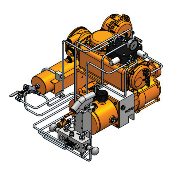
Installation, Operation and Maintenance Manual Section 5: Operation VCIOM-13254-EN Rev. 3 February 2021 Section 5: Operation After initial start-up and commissioning procedures have been accomplished, the Bettis EHO Actuator provides a simple self-contained means of operation for a quarter-turn valve. In case of a power failure the actuator can be operated by the use of the suppliedhandpump. - Page 40 Section 5: Operation Installation, Operation and Maintenance Manual February 2021 VCIOM-13254-EN Rev. 3 NOTE: Item numbers correspond to attached schematic drawing 11794-S. Bettis G-series Double-acting Actuator Electric Motor Hydraulic Pump Fluid Reservoir 3-Way Normally Closed Solenoid Valve for closing the actuator 3-Way Normally Closed Solenoid Valve for opening the actuator Adjustable Flow Controls.
- Page 41 Installation, Operation and Maintenance Manual Section 5: Operation VCIOM-13254-EN Rev. 3 February 2021 Figure 24 Main Components Double-acting with ESD Solenoid and Accumulator (A) Pressure Gauge (Optional) Pressure Gauge (Optional) (B) Nitrogen Relief Valve (Optional) Nitrogen Relief Valve (Optional) (D) Isolation Valve (Optional) Isolation Valve (Optional) Hydraulic Accumulator With Nitrogen Blanket Charge (Optional) Hydraulic Accumulator With Nitrogen Blanket Charge (Optional)
- Page 42 Section 5: Operation Installation, Operation and Maintenance Manual February 2021 VCIOM-13254-EN Rev. 3 Hydraulic Pressure Gauge Pressure Switch Handpump: Used to manually stroke the actuator open or closed. (AD) Optional accumulator override 3-way isolation valve to open the actuator. (AE) Optional accumulator override 3-way isolation valve to close the actuator. Handpump Selection Valves: These two valves are engaged to isolate the control system before using the handpump.
-
Page 43: Functional Description
Installation, Operation and Maintenance Manual Section 5: Operation VCIOM-13254-EN Rev. 3 February 2021 Functional Description The following is a functional description of the Bettis Electro-Hydraulic Actuator and a brief explanation of the main components. Throughout this explanation, numbers which appear in in [ ] correspond to components labeled on the wiring diagram. - Page 44 Section 5: Operation Installation, Operation and Maintenance Manual February 2021 VCIOM-13254-EN Rev. 3 5.4.2.1 Accumulator Charge The motor (Z) drives the hydraulic pump (Y) and discharges fluid to the nitrogen blanket pre-charged accumulator (E). 5.4.2.2 Power Stroke ((Open/Close)) Upon completion of the accumulator charging, the pressure switch (R) set point is reached and stops the motor.
-
Page 45: Section 6: Pushbutton Module (Pbm)
Installation, Operation and Maintenance Manual Section 6: Pushbutton Module (PBM) VCIOM-13254-EN Rev. 3 February 2021 Section 6: Pushbutton Module (PBM) The Pushbutton Module consists of the following as shown in Figure 25: • Two Pilot Lights: OPEN and CLOSE • Three Pushbuttons: OPEN, CLOSE AND STOP •... -
Page 46: Selector Knob And Control Pushbuttons
Section 6: Pushbutton Module (PBM) Installation, Operation and Maintenance Manual February 2021 VCIOM-13254-EN Rev. 3 Selector Knob and Control Pushbuttons The selector knob provides the choice of Local/Off/Remote operation. The control pushbuttons perform normal Open/Stop/Close function in the local control mode. Table 5. -
Page 47: Section 7: Troubleshooting
Installation, Operation and Maintenance Manual Section 7: Troubleshooting VCIOM-13254-EN Rev. 3 February 2021 Section 7: Troubleshooting WARNING To prevent personal injury, the actuator must be in spring-return, Fail-safe Position and all hydraulic pressure drained, including an optional accumulator, before opening any tube lines or attempting replacement operations below. -
Page 48: Hazardous Area Classification And Sil Certification
Section 8: Hazardous Area Classification Installation, Operation and Maintenance Manual February 2021 VCIOM-13254-EN Rev. 3 Section 8: Hazardous Area Classification and SIL Certification — CSA, Canadian Standard Association Certification Class I, Division I, Groups, C and D Group B configuration upon request —... -
Page 49: Section 9: Weights And Dimensions
Installation, Operation and Maintenance Manual Section 9: Weights and Dimensions VCIOM-13254-EN Rev. 3 February 2021 Product Data Sheet EHO.01.05.EN, Page 2 of 2, Rev. 0 March 2015 Section 9: Weights and Dimensions Dimension Double-Acting Actuator EHO Standard Double-Acting CYLINDER CL &</,1'(5 &/ POWER MODULE 32:(5 02'8/(... - Page 50 Holland Fasor 6 Tianjin 301700 P. R. China Székesfehérvár 8000 The Emerson logo is a trademark and service mark of Emerson Electric Co. T +86 22 8212 3300 Hungary Bettis is a mark of one of the Emerson family of companies.
Need help?
Do you have a question about the Bettis Electro-Hydraulic Operated and is the answer not in the manual?
Questions and answers