Table of Contents
Advertisement
Advertisement
Table of Contents

Related Manuals for Manitowoc SF0406A


Summary of Contents for Manitowoc SF0406A
- Page 1 S Model Nugget/Flake Ice Machines Installation, Use & Care Manual This manual is updated as new information and models are released. Visit our website for the latest manual. www.manitowocfsg.com America’s #1 Selling Ice Machine Part Number 000001196 4/08...
- Page 2 Safety Notices Read These Before Proceeding: As you work on Manitowoc equipment, be sure to pay close attention to the safety notices in this manual. ! Caution Disregarding the notices may lead to serious injury and/ Proper installation, care and maintenance are or damage to the equipment.
-
Page 3: Table Of Contents
Manitowoc Cleaner and Sanitizer ........ - Page 4 Table of Contents (continued) Condenser Air Baffle (Air-Cooled Ice Machines Only) ........Electrical Service.
- Page 5 Exterior Cleaning ..........Manitowoc’s Cleaning Technology ........
- Page 6 Table of Contents (continued) Section 5 Before Calling for Service Checklist ............Safeguard Feature.
-
Page 7: Model Numbers
This manual covers the following models: FLAKE AIR-COOLED 9 REMOTE FLAKE WATER-COOLED Self-Contained Self-Contained Traditional AIR-COOLED NUGGET AIR-COOLED NUGGET WATER-COOLED Air-Cooled Water-Cooled Remote* SF0406A SF0407W -------- SN0458A SN0459W -------- SF0606A SF0607W SF0696N S N 0658 A SN0658A SN0659W SN0698N SF0906A SF0907W -------- ICE MACHINE... -
Page 8: Manitowoc Cleaner And Sanitizer
General Information Section 1 Manitowoc Cleaner and Sanitizer ! Caution Manitowoc Ice Machine Cleaner and Sanitizer are RFC Condensing Units: Energize the head available in convenient 16 oz. (473 ml) bottles. Sanitizer section before the condensing unit. This allows the is also available in 1 gal (3.78 l) bottles. -
Page 9: Model/Serial Number Location
The model and serial number are listed on the OWNER information from your local Manitowoc distributor, WARRANTY REGISTRATION CARD. They are also service representative, or Manitowoc Ice, Inc. Record listed on the MODEL/SERIAL NUMBER DECAL affixed the model and serial number of your ice machine and to the ice machine head section and condensing unit. -
Page 10: Owner Warranty Registration Card
If the OWNER WARRANTY REGISTRATION CARD is God. not returned, Manitowoc will use the date of sale to the 4. Premium labor rates due to holidays, overtime, Manitowoc Distributor as the first day of warranty etc.;... -
Page 11: Residential Ice Machine Limited Warranty
To secure prompt and continuing warranty service, this Telephone: 920-682-0161 Fax: 920-683-7585 warranty registration card must be completed and sent www.manitowocice.com to Manitowoc within thirty (30) days from the sale date. Complete the registration card and send it to Manitowoc. Part Number 000001196 3/08... - Page 12 General Information Section 1 THIS PAGE INTENTIONALLY LEFT BLANK Part Number 000001196 3/08...
-
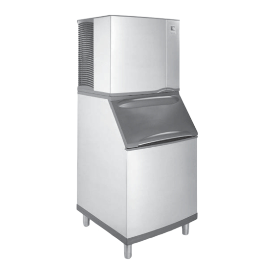
Page 13: Ice Machine Dimensions
Ice Machine Dimensions These instructions are provided to assist the qualified installer. Check your local Yellow Pages for the name of the nearest Manitowoc distributor, or call Manitowoc Ice, Inc. for information regarding start-up services. AIR COOLED ICE MACHINES SF0400/SN0450/SF0600/SN0650/SF0900/SN0950 23.5"... -
Page 14: Water Cooled Ice Machines
Installation Instructions Section 2 WATER COOLED ICE MACHINES SF0400/SN0450/SF0600/SN0650/SF0900/SN0950 23.5" (59.69cm) 6.25" (15.9cm) Condenser Water Inlet Water Outlet 3/8” FPT 2.5" (6.35cm) 26.5" (67.3cm) Condenser Water Inlet 3/8” FPT (Water-Cooled Only) 13.0" (33.0cm) 2.5" (6.4cm) 1.0" Drain Fitting Electrical 1/2” NPTF Entrance 2.5"... -
Page 15: Remote Air Cooled Ice Machines
Section 2 Installation Instructions REMOTE AIR COOLED ICE MACHINES SF0600/SN0650 23.5" (59.69cm) Water Inlet 3/8” FPT 2.5" (6.35cm) 26.5" (67.3cm) Refrigerant Refrigerant Discharge Line Liquid Line 2.5" 12.3" (6.4cm) (31.2cm) 1.0" Drain Fitting Electrical 1/2” NPTF 12.3" Entrance (31.2cm) 2.5" (6.35cm) Auxillary 24.5"... -
Page 16: Remote Unit Dimensions
Installation Instructions Section 2 Remote Unit Dimensions TRADITIONAL REMOTE CONDENSER REMOTE CONDENSING UNIT JC0495 RFC0985/RFC1285 24.13” (53.7 CM) 34” (86.4 CM) 25.75” (65.4 CM) 14.5” (36.8 CM) SV1758 14.5” (36.8 CM) 9.5” (24.1 CM) 10.75” (27.3 CM) Ice Storage Bin Dimensions 30 INCH (76 CM) ICE STORAGE BINS SV1609 Bin Model... -
Page 17: Location Of Ice Machine
Section 2 Installation Instructions Location of Ice Machine Ice Machine Heat of Rejection The location selected for the ice machine must meet the Heat of Rejection following criteria. If any of these criteria are not met, select Ice Machine Model another location. -
Page 18: Installing On A Storage Bin
5. Inspect bin gasket prior to ice machine installation. • A safety issue if ice lifts the adapter or ice machine (Manitowoc bins come with closed cell foam gasket NUGGET DISPENSING KIT INSTALLATION installed along the top surface of the bin.) PROCEDURE 6. -
Page 19: Condenser Air Baffle (Air-Cooled Ice Machines Only)
Section 2 Installation Instructions Condenser Air Baffle (Air-Cooled Ice Machines Only) The air-cooled baffle prevents condenser air from recirculating. To install: 1. Remove the back panel screws next to the condenser. 2. Align the mounting holes in the air baffle with the screw holes and reinstall the screws. -
Page 20: Electrical Service
All electrical work, including wire routing and grounding, presumably to ground. Manitowoc Ice, Inc. does not must conform to local, state and national electrical recommend the use of a GFCI/GFI circuit protection with codes. -
Page 21: Ice Machine Head Section
Section 2 Installation Instructions Electrical Requirements ICE MACHINE HEAD SECTION QuietQube Air-Cooled Water Cooled Air-Cooled Voltage Machine Phase Maximum Minimum Maximum Minimum Maximum Minimum Head Cycle Fuse/Circuit Circuit Fuse/Circuit Circuit Fuse/Circuit Circuit Section Breaker Amps Breaker Amps Breaker Amps 115/1/60 13.7 12.9 SF0400... -
Page 22: Sf400/Sn0450/Sf600/Sn0650/Sf900/Sn0950/Sf1200/Sn1250 - Electrical Wiring Connections
Installation Instructions Section 2 SF400/SN0450/SF600/SN0650/SF900/SN0950/SF1200/SN1250 - Electrical Wiring Connections SELF CONTAINED ICE MACHINE Warning 208-230/3/60 These diagrams are not intended to show proper wire routing, wire sizing, disconnects, etc., only the correct wire connections. All electrical work, including wire routing and grounding, must conform to local, state and national electrical codes. -
Page 23: Sf600/Sn0650 - Remote Electrical Wiring Connections
Section 2 Installation Instructions SF600/SN0650 - Remote Electrical Wiring Connections REMOTE ICE MACHINE 208-230/3/60 Warning These diagrams are not intended to show proper wire routing, wire sizing, disconnects, etc., only the REMOTE correct wire connections. CONDENSER NOTE: FAN All electrical work, including wire routing and MOTOR IS 208-230V grounding, must conform to local, state and national... -
Page 24: Sf0900C/Sn0950C/Sf1200C/Sn1250C Ice Machine Head Section Electrical Wiring Connections
Installation Instructions Section 2 SF0900C/SN0950C/SF1200C/SN1250C Ice Machine Head Section Electrical Wiring Connections 115/60/1 & 208-230/1/50 ICE MACHINE CONDENSING UNIT CONNECTIONS CONNECTIONS L2 = 208-230V L2 = 208-230V GROUND GROUND TO FUSE/ BREAKER. DISCONNECT ALL LINE VOLTAGE DO NOT DISCONNECT GROUND. Warning These diagrams are not intended to show proper wire routing, wire sizing, disconnects, etc., only the... -
Page 25: Water Supply And Drains
Drain lines must have a 1.5 inch drop per 5 feet of Important run (2.5 cm per meter), and must not create traps. If you are installing a Manitowoc water filter system, • The floor drain must be large enough to refer to the Installation Instructions supplied with the accommodate drainage from all drains. -
Page 26: Water Supply And Drain Line Sizing/Connections
Installation Instructions Section 2 WATER SUPPLY AND DRAIN LINE SIZING/CONNECTIONS ! Caution Plumbing must conform to national, state and local codes. Tubing Size Up to Ice Location Water Temperature Water Pressure Ice Machine Fitting Machine Fitting 45°F (7°C) Min. 20 psi (1.4 bar) Min. 3/8"... -
Page 27: Refrigeration System Installation Traditional Remote Ice Machines Only
The 60-month compressor lifting. warranty (including the 24-month labor replacement warranty) will not apply if Manitowoc SN Model Ice ! Caution Machines are installed with a non-Manitowoc The 60-month compressor warranty (including the traditional condenser or remote condensing unit. -
Page 28: Refrigeration Line Set Installation Traditional Remote Ice Machines Only
Manitowoc Ice, Inc., unless 3. Required - Keep outdoor refrigerant line runs as specifically approved in writing by Manitowoc Ice, short as possible. Inc. DOWNWARD HORIZONTAL SPIRAL SV1204 Routing Line Sets... -
Page 29: Calculating Remote Condenser Installation Distances
Section 2 Installation Instructions CALCULATING REMOTE CONDENSER Make the following calculations to make sure the line set INSTALLATION DISTANCES layout is within specifications. Line Set Length 1. Insert the measured rise into the formula below. Multiply by 1.7 to get the calculated rise. The maximum length is 100' (30.5 m). -
Page 30: Lengthening Or Reducing Line Set Lengths
Installation Instructions Section 2 LENGTHENING OR REDUCING LINE SET LENGTHS In most cases, by routing the line set properly, REMOVE FRONT, TOP, AND LEFT SIDE PANEL shortening will not be necessary. When shortening or FOR ACCESS TO RECEIVER VALVE lengthening is required, do so before connecting the line set to the ice machine or the remote condenser. - Page 31 Section 2 Installation Instructions SINGLE CIRCUIT REMOTE CONDENSER ELECTRICAL DISCONNECT DISCHARGE LINE LIQUID LINE TO CIRCUIT BREAKER PANEL ELECTRICAL DISCONNECT ICE MACHINE ELECTRICAL SUPPLY 36.00" (91.44 cm) DROP LIQUID DISCHARGE REFRIGERANT REFRIGERANT LINE LINE SV1615 Typical Single Circuit Traditional Remote Condenser Installation 2-19 Part Number 000001196 3/08...
-
Page 32: Refrigeration System Installation Remote Condensing Unit Only
Important ! Caution Manitowoc remote systems are only approved and warranted as a complete new package. Warranty on Never add more than nameplate charge to the the refrigeration system will be void if a new ice refrigeration system for any application. -
Page 33: Line Set Length
Section 2 Installation Instructions Refrigeration Line Set Installation A. LINE SET LENGTH Remote Condensing Unit Only 100 feet (30.5 m) Length: The maximum measured length the line set can be. GENERAL The receiver is designed to hold a charge sufficient to Refrigeration line set installations consist of vertical and operate the ice machine in ambient temperatures horizontal line set distances between the ice machine... -
Page 34: Suction Line Oil Traps
Install the trap as close as possible to midpoint between followed by a rise, another drop cannot be made. the ice machine head section and remote condensing unit. S-Trap Kits are available from Manitowoc (refer to Step 3 Lengthening or Reducing Line Set Lengths chart). - Page 35 Section 2 Installation Instructions Step 4 Connecting the line set. Connect the Line Set to the Remote Condensing Unit To prevent oxidation of the copper, purge line set and condensing unit with dry nitrogen while brazing. Warning condensing unit ships from factory Connect The Line Set To The Ice Machine Head...
- Page 36 Installation Instructions Section 2 Step 5 Pressure Test and Evacuate The Line Set If required, the line set and condensing unit can be and Remote Condensing Unit evacuated from the schrader valves located in the remote condensing unit. Schrader valve core removal Schrader valve core removal tools that allow for removal tools (that allow for putting the cores back in without and installation of the valve cores without removing...
- Page 37 Section 2 Installation Instructions Step 6 Open The Valves Prior To Starting The Ice Machine. Important A. Slowly backseat (open-turn counterclockwise) All refrigeration valve caps must be reinstalled to the suction line shut off valve. prevent future refrigeration leaks. B. Slowly backseat (open-turn counterclockwise) the liquid line shut off valve.
- Page 38 Installation Instructions Section 2 Step 7 Leak Check The Refrigeration System Suction Shut Off Valve Insulation Leak check the new line set connections at the ice The pre-formed suction shut-off valve insulation is machine head section, condensing unit and S trap as located in the plastic bag taped to the water curtain.
- Page 39 Section 2 Installation Instructions REMOTE CONDENSING UNIT ELECTRICAL DISCONNECT SUCTION LINE LIQUID LINE INTERCONNECTING WIRING ICE MACHINE HEAD SECTION ELECTRICAL DISCONNECT SUCTION REFRIGERANT SHUT-OFF VALVE ELECTRICAL LIQUID SUPPLY REFRIGERANT SHUT-OFF VALVE SV1759 Typical QuietQube System Installation 2-27 Part Number 000001196 3/08...
-
Page 40: Installation Checklist
Section 2 Installation Check List All Manitowoc ice machines are factory-operated and adjusted before shipment. Adjustments and maintenance procedures outlined in this manual are the responsibility of the owner/operator and are not covered by the warranty. Is the Ice Machine level? -
Page 41: Additional Checks For Remote Models
Section 2 Installation Instructions Additional Checks for Remote Models Is the lineset length, rise and drop within Have all the refrigeration fittings and joints the guidelines? been leak checked? Has the receiver service valve been Is the line set routed properly? opened? Has the condenser/condensing unit been Has the traditional remote condenser been... - Page 42 Installation Instructions Section 2 THIS PAGE INTENTIONALLY LEFT BLANK 2-30 Part Number 000001196 3/08...
-
Page 43: Component Identification
Section 3 Operation Component Identification ICE MACHINE HEAD SECTION AIR-COOLED ICE CHUTE CONDENSER FAN MOTOR WATER INLET WATER RESERVOIR AIR-COOLED CONDENSER EVAPORATOR COMPRESSOR AIR BAFFLE ELECTRICAL GEAR GEAR BOX DRAIN FITTING DUMP VALVE ENTRANCE MOTOR COOL VAPOR VALVE QuietQube Only HALL EFFECT SUCTION SWITCH... -
Page 44: Operational Checks
Operation Section 3 Operational Checks GENERAL Warning Manitowoc ice machines are factory-operated and Potential Personal Injury Situation adjusted before shipment. Normally, a newly installed ice Do not operate equipment that has been misused. machine does not require any adjustment. abused, neglected, damaged, or altered/modified from that of original manufactured specifications. -
Page 45: Sequence Of Operation
Section 3 Operation Sequence of Operation PRIOR TO STARTUP RESTART AFTER AUTOMATIC SHUTOFF When the toggle switch is placed in the ICE position the The 5 minute delay period must be expired. The delay following must occur in the listed order before ice period starts when the ice machine enters Automatic making will start. -
Page 46: Control Board Features
Operation Section 3 Control Board Features FLUSH CYCLE After the ice machine has completed 50 hours of run time a flush sequence will start. This cycle will drain and refill the evaporator to remove minerals that have settled to the bottom of the evaporator. The flush sequence lasts approximately 21 minutes, after which the ice machine will reset the 50 hour counter and automatically start ice making again. -
Page 47: Cleaning And Sanitizing
An extremely dirty ice machine must be taken apart for cleaning and sanitizing. Manitowoc Ice Machine Cleaner and Sanitizer are the only products approved for use in Manitowoc ice machines. ! Caution... -
Page 48: Manitowoc's Cleaning Technology
Maintenance Section 4 Manitowoc’s Cleaning Technology This Manitowoc Ice Machine has three separate cleaning procedures. Manitowoc Flake/Nugget Ice Machines include Preventative Maintenance Cleaning Procedure technology that allows the initiation and completion of a cleaning cycle at the flip of a switch. This cycle will... -
Page 49: Preventative Maintenance Cleaning Procedure
Ice machine cleaner is used to remove lime scale or other mineral deposits. It is not used to remove algae or slime. Refer to “Sanitizing Procedure” for removal of algae and slime. To initiate a cleaning cycle using Manitowoc’s Cleaning Technology use the following procedure. -
Page 50: Procedure To Clean Heavily Scaled Flake/Nugget Ice Machines
Maintenance Section 4 PROCEDURE TO CLEAN HEAVILY SCALED FLAKE/NUGGET ICE MACHINES Ice machines that are heavily scaled or have not been cleaned on a regular basis will need to run this Procedure. Failure to do so may result in binding of the auger as the lime scale releases from the auger and evaporator barrel. Step 1 Remove panels and set the ICE/OFF/CLEAN Step 7 Turn on the water supply to the ice machine. -
Page 51: Cleaning Procedure
Step 7 Remove the top cover from the ice chute and ! Caution pour the cleaner/water solution into the evaporator. Add Use only Manitowoc approved Ice Machine Cleaner the entire amount of premixed solution (excess solution part number 000000084. It is a violation of Federal... -
Page 52: Sanitizing Procedure
Maintenance Section 4 SANITIZING PROCEDURE Ice machine sanitizer is used to remove algae or slime. It is not used to remove lime scale or other mineral deposits. Refer to the “Cleaning Procedure” for removal of lime scale or other mineral deposits. NOTE: Sanitizing must be performed on adjacent surface areas not contacted by the water distribution system. -
Page 53: Component Disassembly For Cleaning And Sanitizing
Section 4 Maintenance Component Disassembly For Cleaning And 6. Turn ice wiper counterclockwise to remove. Sanitizing The ice machine must be disassembled cleaned and sanitized every six months. Warning Wear rubber gloves and safety goggles (and/or face shield) when handling Ice Machine Cleaner or Sanitizer. - Page 54 Maintenance Section 4 11. Lift out ice damper. 13. Loosen ice chute hose clamp. 14. Disconnect ice chute drain. 12. Lift out ice strainer ramp. Ice Chute Drain and Hose Clamp Part Number 000001196 3/08...
- Page 55 Section 4 Maintenance 15. Lift up on ice chute to remove. 17. Remove ice chute collar and tube by lifting straight up.. 16. The ice chute can be cleaned in place. If complete removal is desired use a phillips screwdriver to remove the Hall Effect Switch assembly from the ice chute.
- Page 56 Maintenance Section 4 22. .Mix a solution of sanitizer and warm water. Solution Type Water Mixed With ! Caution Sanitizer 6 gal. (23 l) 4 oz (120 ml) sanitizer Do not mix Cleaner and Sanitizer solutions together. It is a violation of Federal law to use these solutions 23.
- Page 57 Section 4 Maintenance Water Dump Valve The water dump valve normally does not require COIL removal for cleaning. To determine if removal is necessary: 1. Set the toggle switch to ICE. SPRING 2. Verify the water reservoir fills with water at the beginning of the freeze cycle.
-
Page 58: Cleaning The Condenser
Maintenance Section 4 Cleaning the Condenser Water-Cooled Condenser and Water Regulating Valve Symptoms of restrictions in the condenser water circuit Warning include: Disconnect electric power to the ice machine and the remote condenser at the electric service switch • Low ice production before cleaning the condenser. -
Page 59: Removal From Service/Winterization
Section 4 Maintenance Removal from Service/Winterization Self-Contained Water-Cooled Ice Machines 1. Perform steps 1-5 under “Self-Contained Air-Cooled GENERAL Ice Machines.” Special precautions must be taken if the ice machine 2. Disconnect the incoming water and drain lines from head section is to be removed from service for an the water-cooled condenser. - Page 60 Maintenance Section 4 THIS PAGE INTENTIONALLY LEFT BLANK 4-14 Part Number 000001196 3/08...
-
Page 61: Before Calling For Service
Section 5 Before Calling for Service Checklist If a problem arises during operation of your ice machine, follow the checklist below before calling for service. Routine adjustments and maintenance procedures are not covered by the warranty. Problem Possible Cause To Correct Ice machine does not operate No electrical power to the ice machine Reset the breaker/turn on main power switch/... -
Page 62: Safeguard Feature
Before Calling for Service Section 5 Safeguard Feature In addition to standard safety controls, your Manitowoc ice machine features built-in SafeGuards. The ice machine will stop when conditions arise that would cause major component failure. GENERAL SafeGuards The ice machine control board has safety features to 1. -
Page 63: Safeguard Modes
Section 5 Before Calling for Service SafeGuard Modes NO WATER During the Freeze cycle if the water sensing switch WATER LEVEL SENSOR OPEN: opens or remains open for more than 20 continuous The ice machine will wait for the water level sensor to seconds, close. -
Page 64: No Ice Production
Before Calling for Service Section 5 NO ICE PRODUCTION The damper door (HES1) fails to open and close at least NO ICE PRODUCTION: once during the first 8 minutes of compressor run time The ice machine will start another 60 minute Standby Mode. - Page 65 Section 5 Before Calling for Service THIS PAGE INTENTIONALLY LEFT BLANK Part Number 000001196 3/08...
- Page 66 Before Calling for Service Section 5 THIS PAGE INTENTIONALLY LEFT BLANK Part Number 000001196 3/08...
- Page 68 © 2007 Manitowoc Continuing product improvements may necessitate change of specifications without notice. Part Number 000001196 3/08 Manitowoc Foodservice Group 2110 South 26th Street, P.O. Box 1720 Manitowoc, WI 54221-1720, USA Ph: 920-682-0161 Fax: 920-683-7589 Visit us online at: www.manitowocfsg.com...
Need help?
Do you have a question about the SF0406A and is the answer not in the manual?
Questions and answers