Manitowoc QR0670C Technician Manual

Manitowoc QR0670C Technician Manual

Quietqube series
Table of Contents

Advertisement

Manitowoc
Q Model
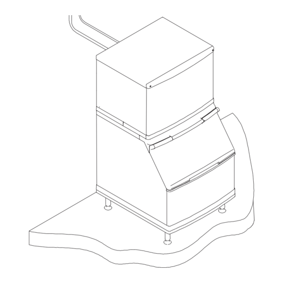
QuietQube
®
Ice Machines
Technician's
Handbook
This manual is updated as new information and models are
released. Visit our website for the latest manual.
www.manitowocice.com
America's #1 Selling Ice Machine
Part Number 80-0099-9 6/11
Advertisement

Table of Contents
loading
Need help?

Need help?

Do you have a question about the QR0670C and is the answer not in the manual?

Questions and answers

Summary of Contents for Manitowoc QR0670C

  • Page 1 Manitowoc Q Model QuietQube ® Ice Machines Technician’s Handbook This manual is updated as new information and models are released. Visit our website for the latest manual. www.manitowocice.com America’s #1 Selling Ice Machine Part Number 80-0099-9 6/11...
  • Page 3: Safety Notices

    Safety Notices As you work on Manitowoc equipment, be sure to pay close attention to the safety notices in this handbook. Disregarding the notices may lead to serious injury and/or damage to the equipment. Throughout this handbook, you will see the following...
  • Page 4 ! Caution Proper installation, care and maintenance are essential for maximum performance and trouble- free operation of your Manitowoc equipment. If you encounter problems not covered by this handbook, do not proceed, contact Manitowoc Foodservice Group. We will be happy to provide assistance.
  • Page 5: Table Of Contents

    Table of Contents Model Numbers Model/Serial Number Location ......2 Ice Machine Warranty Information Owner Warranty Registration Card ....... 3 Warranty Coverage ..........4 General............. 4 Parts ..............4 Labor ..............4 Exclusions ............4 Authorized Warranty Service......5 Service Calls............. 5 Installation Location of Ice Machine ........
  • Page 6 QuietQube® Ice Machines and  CVD® Condensing Units ........ 13 3 Phase Scroll Compressor Rotation....13 Refrigeration System Installation......15 Usage With Non-Manitowoc  Condensing Units ........... 15 Factory Equipment Refrigerant Amounts..16 Refrigeration Line Set Installation....17 3 Phase Scroll Compressor Rotation ...
  • Page 7 Component Identification Ice Machine Head Section ........65 Q0600C/Q0800C/Q1000C ......65 SU1000C/SerVend UC-300 Dispenser ..67 Q1400C ............68 QDUAL ............69 ® Condensing Unit ........70 CVD0675/CVD0875/CVD1075/CVD1475 ..70 CVD1476 ............71 CVD1875/CVD2075 ........72 Ice Making Sequence of Operation Q0600C/Q0800C/Q1000C/SU1000C ....
  • Page 8 Electrical System Component Specifications and Diagnostics Control Board ..............91 Harvest/Safety Limit Light....... 91 Freeze Time Lock-In Feature ......91 Maximum Freeze Time ........91 Safety Limits ........... 91 Three-Minute Delay ........92 Inputs .............. 92 Control Board Relays........92 Main Fuse............
  • Page 9 Refrigeration System Refrigeration System Diagnostics ..... 123 General............123 Refrigeration System Operation ....123 Ice Machine will Not Harvest Diagnostics ..127 Harvest Cycle Diagnostic List....... 127 Ice Production Check ........128 Installation/Visual Inspection Checklist..129 Water System Checklist ....... 130 Ice Formation Pattern ........
  • Page 10 Cycle Times/24-Hour Ice Production/Refrigerant Pressure Charts Q0600C/CVD675 Series Remote Air Cooled ..177 Q0800C/CVD875 Series Remote Air Cooled ..178 Q1000C/CVD1075 Series Remote Air Cooled .. 179 SU1000C/SerVend UC-300 Dispenser/CVD1075 Remote Air Cooled ..........180 Q1400C/CVD1475 Series Remote Air Cooled .. 181 Q1400C/CVD1476 Remote water Cooled..
  • Page 11: Model Numbers

    Model Numbers This manual covers the following models: ® Ice Machine Head Condensing Section Unit* QR0670C QD0672C CVD0675 QY0674C QR0870C QD0872C CVD0875 QY0874C QR1070C CVD1075 QD1072C CVD1285 QY1074C SU1024YC/SerVend CVD1075 UC-300 Dispenser QR1470C CVD1375 QD1472C CVD1475 QY1474C CVD1476 QRDUALC CVD1875...
  • Page 12: Model/Serial Number Location

    Manitowoc F style bins. Prior to using a non-Manitowoc ice storage system with Manitowoc ice machines, contact the manufacturer to assure their ice deflector is compatible with Manitowoc ice machines.
  • Page 13: Ice Machine Warranty Information

    REGISTRATION CARD as soon as possible to validate the installation date. If the OWNER WARRANTY REGISTRATION CARD is not returned, Manitowoc will use the date of sale to the Manitowoc Distributor as the first day of warranty coverage for your new ice machine.
  • Page 14: Warranty Coverage

    The following Warranty outline is provided for your convenience. For a detailed explanation, read the warranty bond shipped with each product. Contact your local Manitowoc representative or Manitowoc Ice, Inc. if you need further warranty information. Important This product is intended exclusively for commercial application.
  • Page 15: Authorized Warranty Service

    Authorized Warranty Service To comply with the provisions of the warranty, a refrigeration service company qualified and authorized by your Manitowoc Distributor, or a Contracted Service Representative must perform the warranty repair. NOTE: If the dealer you purchased the ice machine...
  • Page 16: Installation Location Of Ice Machine

    Installation LOCATION OF ICE MACHINE The location selected for the ice machine head section must meet the following criteria. If any of these criteria are not met, select another location.  The location must be free of airborne and other contaminants.
  • Page 17: Stacking Two Ice Machines On A

    Q1400C/QDUAL Ice Machines:  Q1400C and QDUAL ice machines cannot be stacked. However two Q1400C/QDUAL ice machines can be placed side by side on a 60 in. Manitowoc F style bin. ICE DEFLECTOR QDUAL ice machines mounted on an ice dispenser do not require an ice deflector.
  • Page 18: Location Of Cvd Condensing Unit

    ® LOCATION OF CVD CONDENSING UNIT ® The location selected for the CVD Condensing Unit must meet the following criteria. If any of these criteria are not met, select another location.  The air temperature must be at least -20°F (-28.9°C), but must not exceed 130°F (54.4°C)...
  • Page 19: Ice Machine Head Section Water  Supply And Drains

    Important If you are installing a Manitowoc water filter system, refer to the Installation Instructions supplied with the filter system for ice making water inlet connections. Potable Water Inlet Lines Follow these guidelines to install water inlet lines: ...
  • Page 20: Drain Connections

    Drain Connections Follow these guidelines when installing drain lines to prevent drain water from flowing back into the ice machine and storage bin:  Drain lines must have a 1.5 in. drop per 5 ft. of run (2.5 cm per meter), and must not create traps. ...
  • Page 21: Supply And Drains

    WATER COOLED CONDENSER WATER  SUPPLY AND DRAINS Condenser Water Supply Local water conditions may require treatment of the water to inhibit scale formation to filter sediment. Water Cooled Condenser Lines Follow these guidelines to install water lines:  Contact your distributor if your water pressure is greater than 150 psi (1034kPA).
  • Page 22: Condensing Unit Drain Connections

    Condensing Unit Drain Connections The condensing unit drain is provided to remove any condensate produced by the suction accumulator. Condensate amounts will vary depending on temperature and humidity.  The condensing unit must be level front to back and side to side to allow the condensate to drain. ...
  • Page 23: Electrical Requirements

    ELECTRICAL REQUIREMENTS Ice Machines and  ® QuietQube ® Condensing Units Ice Machine Head Section Voltage Max. Fuse/ Total Phase Circuit Amps Cycle Breaker Q0600C Q0800C Q1000C 115/1/60 15 amp SU1000C 230/1/50 15 amp Q1400C QDUAL Important ® The QuietQube Ice Machine Head Section and ®...
  • Page 24 ® Condensing Unit Voltage Max. Fuse/ Min. Phase Circuit Circuit Cycle Breaker Amps 208-230/1/60 15 amp CVD0675 208-230/3/60 15 amp 230/1/50 15 amp 208-230/1/60 20 amp 11.7 CVD0875 208-230/3/60 15 amp 230/1/50 20 amp 11.3 208-230/1/60 25 amp 15.6 CVD1075 208-230/3/60 20 amp 10.6...
  • Page 25: Refrigeration System Installation

    5/8 in. RC 22/32/52 (19 mm) (22.2 mm) (15.9 mm) Liquid Line 1/4" (7 mm) Usage With Non-Manitowoc Condensing Units ® Manitowoc CVD Condensing Units are specifically ® designed for usage with a QuietQube Ice Machine Head Section. Standard condensing units will not ®...
  • Page 26: Factory Equipment Refrigerant Amounts

    The 60-month compressor warranty (including the 36-month labor replacement warranty) will not apply ® if the Manitowoc Ice Machine and Manitowoc CVD Condensing Unit are not installed according to specifications. This warranty also will not apply if the refrigeration system is modified with a condenser, heat reclaim device, or other parts or assemblies not manufactured by Manitowoc Ice, Inc.
  • Page 27: Refrigeration Line Set Installation

    Warning Potential Personal Injury Situation The ice machine head section contains the refrigerant charge. Installation and brazing of the line sets must be performed by a properly trained refrigeration technician aware of the dangers of dealing with refrigerant charged equipment. Refrigeration Line Set Installation Refrigeration line set installation consists of vertical and horizontal line set distances between the ice...
  • Page 28 B. LINE SET RISE OR DROP 35 FT. (10.7 M) MAXIMUM DISTANCE SV1751 ® 35 ft. (10.7 m) Rise: The maximum distance the CVD Condensing Unit can be above the ice machine. 15 FT. (4.5 M) MAXIMUM DISTANCE SV1750 ® 15 ft.
  • Page 29 (“S” type) to be installed. Install the trap as close as possible to midpoint ® between the ice machine head section and CVD Condensing Unit. S-Trap Kits are available from Manitowoc (refer to chart). 21 FT. OR MORE RISE ADDITIONAL TRAP KIT REQUIRED.
  • Page 30 Manitowoc S-Trap Kit Model S-Trap Kit # Tubing Size Q0600C 5/8 in. K00172 Q0800C (15.9 mm) Q1000C 3/4 in. SU1000C K00166 (19.1 mm) Q1400C 7/8 in. QDUAL K00164 (22.2 mm) SV1760 SERVICE LOOP A service loop in the line set permits easy access to the ice machine for cleaning and service.
  • Page 31 Step 3. When the line set requires shortening or lengthening, do so before connecting the line set to ® the ice machine head section or the CVD Condensing Unit. ! Caution Do not form unwanted traps in refrigeration lines. Never coil excess refrigeration tubing. Step 4.
  • Page 32 ® CONNECT THE LINE SET TO THE CVD CONDENSING UNIT Warning The condensing unit ships from the factory pressurized with a 50/50 mixture of nitrogen/helium. Bleed off pressure from both suction and liquid line access ports prior to cutting into refrigeration lines. The compressor oil rapidly absorbs moisture.
  • Page 33 Liquid Line SV3077 Suction Line Step 5. Schrader valve core removal tools that allow for removal and installation of the valve cores without removing manifold gauge set hoses are recommended to decrease the evacuation time. Leave the line set shut-off valves closed (front seated). ®...
  • Page 34 ALTERNATE CONNECTIONS AT CONDENSING UNIT SCHRADER VALVES PT1284 If required, the line set and condensing unit can be evacuated from the schrader valves located in the ® Condensing Unit. Schrader valve core removal tools (that allow for putting the cores back in without removing vacuum pump hoses) must be used if evacuating from the condensing unit side.
  • Page 35: Q0600C/Q0800C/Q1000C

    Step 6. The suction line, liquid line and receiver service valves are closed during shipment and installation. Open the valves prior to starting the ice machine. A. Slowly backseat (open – turn counterclockwise) the suction line shut-off valve. B. Slowly backseat (open – turn counterclockwise) the liquid line shut-off valve.
  • Page 36 Important All refrigeration valve caps must be reinstalled to prevent future refrigeration leaks. TURN COUNTERCLOCKWISE TO OPEN. RECEIVER SERVICE VALVE CAP (TURN COUNTERCLOCKWISE TO REMOVE.) SV1756 RECEIVER SERVICE VALVE Verify O-rings in schrader valve caps are intact and reinstall on shut-off valves to prevent refrigerant leakage.
  • Page 37 pressures to equalize. Place the ICE/OFF/CLEAN toggle switch in the OFF position. Connect power to ® the CVD Condensing Unit and allow system to pump down. Step 8. To prevent condensation, the entire suction line including the shut-off valve must be insulated. All insulation must be airtight and sealed at both ends.
  • Page 38 SUCTION SHUT-OFF VALVE INSULATION The preformed suction shut-off valve insulation is located in the plastic bag taped to the water curtain. PREFORMED INSULATION TIGHTEN VALVE CAPS TO SPECIFICATIONS. A. Verify valve and schrader caps are tightened to specifications (see step 6). PLACE TAB BETWEEN VALVE BODY AND PANEL.
  • Page 39: Cvd2075 Only

    3 PHASE SCROLL COMPRESSOR ROTATION CVD2075 ONLY A trained and qualified technician must verify compressor rotation at equipment startup or compressor warranty will be void. Incorrect rotation of a scroll compressor can be identified by:  Noisy compressor operation  Elevated suction pressure ...
  • Page 40: Operational Checks General

    Operational Checks GENERAL Your Manitowoc ice machine was factory-operated and adjusted before shipment. Normally, a newly installed ice machine does not require any adjustment. To ensure proper operation, always perform these Operational Checks when starting the ice machine:  For the First Time ...
  • Page 41: Q1400C/Su1000C

    Q1400C/SU1000C 1. Check the water level while the ice machine is in the Clean mode and the water pump is running. The correct water level above the water pump impeller housing is:  Q1400C - 1/8-1/2 in. (3-12.5 mm)  SU1000C - 1/8-1/4 in. (3-6.35 mm) 2.
  • Page 42: Ice Thickness Check

    ICE THICKNESS CHECK After a Harvest cycle, inspect the ice cubes in the ice storage bin. The ice thickness probe is set to maintain an ice bridge of 1/8 in. (3.2 mm). If an adjustment is needed, follow the steps below. 1.
  • Page 43: Harvest Sequence Water Purge

    HARVEST SEQUENCE WATER PURGE Q0600C/Q0800C/Q1000C/SU1000C/QDUAL The Harvest sequence water purge adjustment may only be used when the ice machine is hooked up to special water systems, such as a de-ionized water treatment system. Important The Harvest sequence water purge is factory-set at 45 seconds.
  • Page 44: Interior Cleaning And Sanitizing

    Accessory. If required, an extremely dirty ice machine may be taken apart for cleaning and sanitizing. ! Caution Use only Manitowoc approved Ice Machine Cleaner (part number 94-0546-3) and Sanitizer (part number 94-0565-3). It is a violation of Federal law to use these solutions in a manner inconsistent with their labeling.
  • Page 45 Manitowoc’s Patented Cleaning or Sanitizing Technology Manitowoc ice machines include technology that allows the initiation and completion of a cleaning or sanitizing cycle at the flip of a switch. This cycle will permit cleaning or sanitizing of all surfaces that come in contact with the water distribution system.
  • Page 46: Alphasanò

     ALPHASAN  The goal of AlphaSan is to keep the plastic surfaces of an ice machine cleaner, by reducing or delaying the formation of biofilm. The active ingredient in  AlphaSan is the element silver in the form of silver ...
  • Page 47: Cleaning Procedure

    Clean light* will turn on to indicate the ice machine is in the cleaning mode. Step 3. Wait about one minute or until water starts to flow over the evaporator. Step 4. Add the proper amount of Manitowoc Ice Machine Cleaner to the water trough. ® QuietQube...
  • Page 48 Step 5. The ice machine will automatically time out a ten-minute cleaning cycle, followed by six Rinse cycles, and then stop. The Clean light* will turn off to indicate the cleaning mode is completed. This entire cycle lasts approximately 25 minutes. NOTE: Periodic cleaning must be performed on adjacent surface areas not contacted by the water distribution system.
  • Page 49: Sanitizing Procedure

    Clean light* will turn on to indicate the ice machine is in the cleaning mode. Step 3. Wait about one minute or until water starts to flow over the evaporator. Step 4. Add the proper amount of Manitowoc Ice Machine Sanitizer to the water trough. ® QuietQube...
  • Page 50 Step 5. The ice machine will automatically time out a ten-minute sanitizing cycle, followed by six Rinse cycles, and then stop. The Clean light* will turn off to indicate the sanitizing mode is completed. This entire cycle lasts approximately 25 minutes. NOTE: Periodic cleaning must be performed on adjacent surface areas not contacted by the water distribution system.
  • Page 51: Automatic Cleaning System (Aucs ) Accessory

    ® Automatic Cleaning System (AuCS ) Accessory This accessory monitors ice-making cycles and initiates cleaning (or sanitizing) procedures ® automatically. The AuCS Accessory can be set to automatically clean or sanitize the ice machine every 2, 4, or 12 weeks. Periodic maintenance must be performed that includes cleaning or sanitizing the bin (or dispenser) and adjacent surface areas, which can not be contacted by the water distribution system.
  • Page 52 MANUAL START OPERATION Step 1. Set the toggle switch to the OFF position after ice falls from the evaporator at the end of a Harvest cycle. Or, set the switch to the OFF position and allow the ice to melt off the evaporator. ! Caution Never use anything to force ice from the evaporator.
  • Page 53: Removal Of Parts For Cleaning Or Sanitizing

    Removal of Parts for Cleaning or Sanitizing 1. Turn off the water supply to the ice machine at the water service valve. Warning Disconnect electric power to the ice machine at the electric switch box before proceeding. 2. Remove the water curtain and the components you want to clean or sanitize.
  • Page 54 ! Caution Do not immerse the water pump motor in the cleaning or sanitizing solution. 5. Use the solution and a brush to clean the top, sides, and bottom evaporator extrusions; the inside of the ice machine panels; and the entire inside of the bin.
  • Page 55 WATER DUMP VALVE The water dump valve normally does not require removal for cleaning. To determine if removal is necessary: 1. Locate the water dump valve. 2. Set the toggle switch to ICE. 3. While the ice machine is in the Freeze mode, check the dump valve’s clear plastic outlet drain hose for leakage.
  • Page 56 RETAINING DO NOT DISCONNECT WIRES AT COIL. VALVE WATER SHIELD DUMP VALVE DUMP VALVE REMOVAL Important The plunger and the inside of the enclosing tube must be completely dry before assembly. NOTE: During cleaning, do not stretch, damage or remove the spring from the plunger. If it is removed, slide the spring’s flared end into the plunger’s slotted top opening until the spring contacts the plunger spring stop.
  • Page 57 WATER PUMP Warning Disconnect the electric power to the ice machine at the electric service switch box and turn off the water supply. 1. Disconnect the water pump power cord. LOOSEN SCREWS. POWER CORD WATER PUMP SV1618 WATER PUMP REMOVAL (Q0600C/Q0800C/Q1000C SHOWN) 2.
  • Page 58 ICE THICKNESS PROBE 1. Compress the side of the ice thickness probe near the top hinge pin and remove it from the bracket. DISCONNECT WIRE LEAD. COMPRESS HINGE PIN TO REMOVE. SV1619 ICE THICKNESS PROBE REMOVAL NOTE: At this point, the ice thickness probe can easily be cleaned.
  • Page 59 WATER LEVEL PROBE Q0600C/Q0800C/Q1000C/QDUAL 1. Loosen the screw that holds the water level probe in place. The probe can easily be cleaned at this point without proceeding to step 2. Warning Disconnect the electrical power to the ice machine at the electrical disconnect before proceeding.
  • Page 60 SPLASH SHIELD Q1400C/QDUAL 1. Pull forward on left and right Nylatch connectors until disengaged from ice machine (connectors remain attached to splash shield). 2. Remove panel from front of ice machine by lifting forward and up. NYLATCH CONNECTORS Q1400 Shown PULL FORWARD TO DISENGAGE.
  • Page 61 WATER CURTAIN 1. Gently flex the curtain in the center and remove it from the right side. SV1213 WATER CURTAIN REMOVAL 2. Slide the left pin out. –51–...
  • Page 62 FLOAT VALVE SU1000C/Q1400C 1. Turn off the water supply to the ice machine at the water service valve. 2. Turn the splash shield counterclockwise one or two turns. WATER INLET TUBE COMPRESSION FITTING ON/OFF SLIDE SWITCH FILTER SCREEN AND CAP SPLASH SHIELD SV1217...
  • Page 63 WATER INLET VALVE Q0600C/Q0800C/Q1000C/QDUAL The water inlet valve normally does not require removal for cleaning. Follow the instructions below to determine if removal is necessary. 1. Set the ICE/OFF/CLEAN switch to OFF. Locate the water inlet (in the water area of the ice machine). It directs water into the water trough.
  • Page 64 Follow the procedure below to remove the water inlet valve. 1. Remove the valve shield if necessary. 2. Remove the filter access screws that hold the valve in place. NOTE: The water inlet valve can be disassembled and cleaned without disconnecting the incoming water supply line to the ice machine.
  • Page 65 WATER DISTRIBUTION TUBE 1. Disconnect the water hose from the distribution tube. 1. LIFT UP. 2. SLIDE BACK. 3. SLIDE TO RIGHT. THUMB- SCREW DISTRIBUTION TUBE SV1620 THUMBSCREW WATER DISTRIBUTION TUBE REMOVAL 2. Loosen the thumbscrews, which secure the distribution tube. 3.
  • Page 66 4. Disassemble for cleaning. A. Twist both of the inner tube ends until the tabs line up with the keyways. INNER TUBE INNER TUBE KEYWAY SV1211 WATER DISTRIBUTION TUBE DISASSEMBLY B. Pull the inner tube ends outward. –56–...
  • Page 67 WATER TROUGH REMOVAL Q1400C/QDUAL 1. Remove the front splash shield, water pump and float valve from the ice machine. 2. Remove the quarter turn fasteners (turn counterclockwise) securing the trough in place. 3. Lift up and forward on the front of the water trough while allowing the rear of the water trough to drop.
  • Page 68: Su1000C/Servend Uc-300 Dispenser

    WATER TROUGH REMOVAL SU1000C (SerVend UC-300 Dispenser) 1. Remove the quarter turn fasteners (turn counterclockwise) securing the trough in place. 2. Pull forward on the water trough until the rear pins disengage from the water trough. 3. Lift up and forward on the front of the water trough while allowing the rear of the water trough to drop.
  • Page 69: Removal From Service/Winterization General

    Removal from Service/Winterization GENERAL Special precautions must be taken if the ice machine is to be removed from service for an extended period of time or exposed to ambient temperatures of 32°F (0°C) or below. ! Caution If water is allowed to remain in the ice machine in freezing temperatures, severe damage to some components could result.
  • Page 70: Cvd1476 Water Cooled Condensing Unit

    CVD1476 WATER COOLED CONDENSING UNIT Place the ice machine toggle switch into the OFF position. 1. "Front seat" (shut off) the receiver service valve. Hang a tag on the switch as a reminder to open the valve before restarting. 2. Perform steps 1-6 under "Q1400C Head Section". 3.
  • Page 71 Component Identification ICE MACHINE HEAD SECTION Q0600C/Q0800C/Q1000C COOL VAPOR VALVE LIQUID LINE SOLENOID VALVE WATER INLET VALVE RECEIVER SERVICE VALVE SUCTION LINE SHUT-OFF VALVE RECEIVER LIQUID LINE WATER DUMP SHUT-OFF VALVE VALVE DRAIN HOSE SV1754 –65–...
  • Page 72 Q0600C/Q0800C/Q1000C FLOW CLAMP USED ON REGULAR SIZE CUBE ONLY DISTRIBUTION ICE THICKNESS EVAPORATOR TUBE PROBE WATER TROUGH WATER PUMP ICE/OFF/CLEAN SWITCH WATER CURTAIN SV1605A –66–...
  • Page 73 SU1000C/SerVend UC-300 Dispenser Electrical Compartment & Toggle Switch Ice Thickness Probe Dump Valve Water Curtain Water Trough Liquid Line Drier Cool Vapor Valve Liquid Line Solenoid Valve Float Valve Water Pump Water Pump/Float Valve Access Panels –67–...
  • Page 74: Aucs® Accessory

    Q1400C Receiver Service Valve THICKNESS PROBE ICE/OFF/CLEAN SWITCH COOL VAPOR FLOAT VALVE VALVE WATER INLET SV1770LH SUCTION LINE SHUT-OFF VALVE LIQUID LINE SHUT-OFF VALVE COOL VAPOR VALVE RECEIVER WATER DUMP SERVICE VALVE VALVE LIQUID LINE SOLENOID RECEIVER VALVE SV1770RH –68–...
  • Page 75: Qdual

    QDUAL EVAPORATOR WATER PUMP DISTRIBUTION TUBE WATER CURTAIN SV1780 WATER TROUGH –69–...
  • Page 76: Cvd ® Condensing Unit

    ® CONDENSING UNIT CVD0675/CVD0875/CVD1075/CVD1475 CONDENSER HEAD PRESSURE FAN MOTOR CONTROL VALVE ACCESS VALVE ELECTRICAL COMPARTMENT AIR CONDENSER LIQUID LINE AND SV2085 SUCTION LINE COMPRESSOR CONNECTION POINTS SUCTION ACCUMULATOR –70–...
  • Page 77: Cvd1476

    CVD1476 HEAD LIQUID LINE AND PRESSURE WATER SUCTION LINE CONTROL REGULATING CONNECTION POINTS VALVE VALVE ELECTRICAL COMPARTMENT WATER COOLED CONDENSER SUCTION ACCUMULATOR COMPRESSOR –71–...
  • Page 78: Cvd1875/Cvd2075

    CVD1875/CVD2075 ACCESS VALVES AIR CONDENSER CONDENSER FAN MOTOR ELECTRICAL HEAD PRESSURE COMPARTMENT CONTROL VALVE LIQUID LINE AND SUCTION LINE CONNECTION POINTS SUCTION ACCUMULATOR COMPRESSOR CVD1875 SHOWN –72–...
  • Page 79: Ice Making Sequence Of Operation

    Ice Making Sequence of Operation Q0600C/Q0800C/Q1000C/SU1000C Initial Start-Up or Start-Up After  Automatic Shut-Off 1. Water Purge Before the compressor starts, the water pump and water dump solenoid are energized for 45 seconds to purge the ice machine of old water. This ensures that the ice-making cycle starts with fresh water.
  • Page 80: Freeze Sequence

    Freeze Sequence 3. Prechill The compressor is on for 30 seconds prior to water flow to prechill the evaporator. The water fill valve remains on until the water level probe is satisfied. 4. Freeze The water pump restarts after the 30-second prechill. An even flow of water is directed across the evaporator and into each cube cell, where it freezes.
  • Page 81: Harvest Sequence

    Harvest Sequence 5. Water Purge The water pump continues to run, and the water dump valve energizes for 45 seconds to purge the water in the sump trough. The water fill valve energizes for the last 15 seconds of the 45-second water purge. After the 45-second water purge, the water fill valve, water pump and dump valve de-energize.
  • Page 82: Automatic Shut-Off

    Automatic Shut-Off 7. Automatic Shut-Off Ice Machine Section: When the storage bin is full at the end of a Harvest sequence, the sheet of ice cubes fails to clear the water curtain and will hold it open. After the water curtain is held open for 7 seconds, the ice machine shuts off.
  • Page 83 Q600C/Q800C/Q1000C/SU1000C Energized Parts Chart Control Board Relays Condensing Unit Ice Making Length Contactor Sequence of Water Water Cool Water Liquid Contactor Comp of Time Operation Pump Fill Vapor Dump Line Coil Fan Motor* Valve Valve Valve Solenoid Initial Start-Up Closed 1.
  • Page 84 Q600C/Q800C/Q1000C/SU1000C Energized Parts Chart Control Board Relays Condensing Unit Ice Making Length Contactor Sequence of Water Water Cool Water Liquid Contactor Comp of Time Operation Pump Fill Vapor Dump Line Coil Fan Motor* Valve Valve Valve Solenoid Harvest Sequence CVD675 30 Sec.
  • Page 85: Q1400C

    Q1400C Initial Start-Up or Start-Up After Automatic Shut-Off 1. Water Purge Before the refrigeration system starts, the water pump and water dump solenoid are energized for 45 seconds, to purge the ice machine of old water. This feature ensures that the ice making cycle starts with fresh water.
  • Page 86 Harvest Sequence 4. Water Purge The water pump continues to run, and the water dump valve energizes for 45 seconds to purge the water in the sump trough. After the 45-second water purge, the water pump and dump valve de-energizes. Both cool vapor solenoid valves also open at the beginning of the water purge to divert refrigerant gas into the evaporator.
  • Page 87: Off

    Energized Parts Chart – Model Q1400C Control Board Relays Condensing Unit Ice Making LPCO* Contactor Length Sequence of Water Cool Cool Water Liquid Contactor Condenser of Time Pump Vapor Vapor Dump Line Coil Fan Motor* Operation Valve Valve Valve Solenoid Compressor Right Left...
  • Page 88: Harvest Sequence

    Energized Parts Chart – Model Q1400C (Continued) Control Board Relays Condensing Unit Ice Making LPCO* Contactor Length Sequence of Water Cool Cool Water Liquid Contactor Condenser of Time Pump Vapor Vapor Dump Line Coil Fan Motor* Operation Valve Valve Valve Solenoid Compressor Right...
  • Page 89 Energized Parts Chart – Model Q1400C (Continued) Control Board Relays Condensing Unit Ice Making LPCO* Contactor Length Sequence of Water Cool Cool Water Liquid Contactor Condenser of Time Pump Vapor Vapor Dump Line Coil Fan Motor* Operation Valve Valve Valve Solenoid Compressor Right...
  • Page 90: Qdual

    QDUAL Initial Start-Up or Start-Up After Automatic Shut-Off 1. Water Purge Before the refrigeration system starts, the water pump and water dump solenoid are energized for 45 seconds, to purge the ice machine of old water. This feature ensures that the ice-making cycle starts with fresh water.
  • Page 91: Freeze Sequence

    Freeze Sequence 3. Prechill The liquid line solenoid is energized for 30 seconds prior to water flow. This allows the refrigeration system to start up and prechill the evaporator. The water fill valve remains energized until the water level sensor is satisfied.
  • Page 92: Harvest Sequence

    Harvest Sequence 5. Water Purge The water pump continues to run, and the water dump valve energizes for 45 seconds to purge the water in the sump trough. The water fill valve energizes for the last 15 seconds of the 45-second water purge. After the 45-second water purge, the water fill valve, water pump, and dump solenoid valve de-energize.
  • Page 93: Board

    6A. Water Assist Harvest Feature Typical duration of a Harvest sequence is less than 2.5 minutes. When the Harvest sequence time reaches 4 minutes, the following occurs: 4 minutes into a Harvest sequence: The water fill valve will energize to fill the trough with water. 5 minutes into a Harvest sequence: The water pump will energize and flow water over the evaporators.
  • Page 94 Energized Parts Chart – Model QDUAL Control Board Relays Condensing Unit Ice Making LPCO* Contactor Length Sequence of Water Water Dump Liquid Cool Cool Contactor Fan Motor of Time Pump Fill Valve Line Vapor Vapor Coil Operation Solenoid Solenoid Valve Valve Compressor Initial Start-Up...
  • Page 95 Energized Parts Chart – Model QDUAL (Continued) Control Board Relays Condensing Unit Ice Making LPCO* Contactor Length Sequence of Water Water Dump Liquid Cool Cool Contactor Fan Motor of Time Pump Fill Valve Line Vapor Vapor Coil Operation Solenoid Solenoid Valve Valve Compressor...
  • Page 96 Energized Parts Chart – Model QDUAL (Continued) Control Board Relays Condensing Unit Ice Making LPCO* Contactor Length Sequence of Water Water Dump Liquid Cool Cool Contactor Fan Motor of Time Pump Fill Valve Line Vapor Vapor Coil Operation Solenoid Solenoid Valve Valve Compressor...
  • Page 97: Electrical System

    Electrical System COMPONENT SPECIFICATIONS AND DIAGNOSTICS CONTROL BOARD ® All QuietQube control boards incorporate the following features. Refer to “Sequence of Operation” for additional information specific to your model. Harvest/Safety Limit Light This light’s primary function is to be on as water contacts the ice thickness probe during the Freeze cycle, and remain on throughout the entire Harvest cycle.
  • Page 98: Three-Minute Delay

    Three-Minute Delay The three-minute delay is initiated whenever the ice machine cycles off (automatic shut-off) on a full bin. The delay period starts when a water curtain is open for 7 continuous seconds in the Harvest cycle.  If the 3-minute delay period has expired, closure of the water curtain will initiate an immediate start-up of a Freeze sequence.
  • Page 99: Main Fuse

    MAIN FUSE Function The control board fuse stops ice machine operation if electrical components fail, causing high amp draw. Specifications The main fuse is 250 Volt, 7 amp. Warning High (line) voltage is applied to the control board (terminals #55 and #56) at all times. Removing the control board fuse or moving the toggle switch to OFF will not remove the power supplied to the control board.
  • Page 100: Bin Switch

    BIN SWITCH Function Movement of the water curtain controls bin switch operation. The bin switch has two main functions: 1. Terminating the Harvest cycle and returning the ice machine to the Freeze cycle. This occurs when the bin switch is opened and closed again within 7 seconds during the Harvest cycle.
  • Page 101: Check Procedure

    Check Procedure 1. Set the toggle switch to OFF. 2. Watch the bin switch light on the control board. 3. Move the water curtain toward the evaporator. The bin switch must close. The bin switch light “on” indicates the bin switch has closed properly. 4.
  • Page 102: Water Curtain Removal Notes

    Water Curtain Removal Notes The water curtain must be on (bin switch closed) to start ice making. While a Freeze cycle is in progress, the water curtain can be removed and installed at any time without interfering with the electrical control sequence.
  • Page 103: Ice/Off/Clean Toggle Switch

    ICE/OFF/CLEAN TOGGLE SWITCH Function The switch is used to place the ice machine in ICE, OFF or CLEAN mode of operation. Specifications Double-pole, double-throw switch. The switch is connected into a varying low D.C. voltage circuit. Check Procedure NOTE: Because of a wide variation in D.C. voltage, it is not recommended that a voltmeter be used to check toggle switch operation.
  • Page 104: Ice Thickness Probe (Harvest Initiation)

    ICE THICKNESS PROBE (HARVEST INITIATION) How the Probe Works Manitowoc’s electronic sensing circuit does not rely on refrigerant pressure, evaporator temperature, water levels or timers to produce consistent ice formation. As ice forms on the evaporator, water (not ice) contacts the ice thickness probe. After the water completes this circuit across the probe continuously for 6-10 seconds, a Harvest cycle is initiated.
  • Page 105: Ice Thickness Probe Diagnostics

    Ice Thickness Probe Diagnostics Before diagnosing ice thickness control circuitry clean the ice thickness probe using the following procedure. 1. Mix a solution of Manitowoc ice machine cleaner and water (2 ounces of cleaner to 16 ounces of water) in a container.
  • Page 106: Diagnosing Ice Thickness Control Circuitry

    Diagnosing Ice Thickness Control Circuitry ICE MACHINE DOES NOT CYCLE INTO HARVEST WHEN WATER CONTACTS THE ICE THICKNESS CONTROL PROBE Step 1. Bypass the freeze time lock-in feature by moving the ICE/OFF/CLEAN switch to OFF and back to ICE. Wait until the water starts to flow over the evaporator.
  • Page 107 Step 3. Disconnect the ice thickness probe from the control board at terminal 1C. Clip the jumper wire leads to terminal 1C on the control board and any cabinet ground. Monitor the Harvest light. Harvest Light On  The harvest light comes on, and 6-10 seconds later, the ice machine cycles from Freeze to Harvest.
  • Page 108 ICE MACHINE CYCLES INTO HARVEST BEFORE WATER CONTACT WITH THE ICE THICKNESS PROBE Step 1. Disconnect the ice thickness probe from the control board at terminal 1C. Step 2. Bypass the freeze time lock-in feature by moving the ICE/OFF/CLEAN switch to OFF and back to ICE.
  • Page 109: Water Level Control Circuitry

    WATER LEVEL CONTROL CIRCUITRY Q0600C/Q0800C/Q1000C/QDUAL Only The water level probe circuit can be monitored by watching the water level light. The water level light is on when water contacts the probe, and off when no water is in contact with the probe. The water level light functions any time power is applied to the ice machine, regardless of toggle switch position.
  • Page 110 FREEZE CYCLE CIRCUITRY Manitowoc’s electronic sensing circuit does not rely on float switches or timers to maintain consistent water level control. During the Freeze cycle, the water inlet valve energizes (turns on) and de-energizes (turns off) in conjunction with the water level probe located in the water trough.
  • Page 111 DIAGNOSING WATER LEVEL CONTROL CIRCUITRY Q0600C/Q0800C/Q1000C/QDUAL Only Problem: Water Trough Overfilling During the Freeze Cycle Step 1. Start a new Freeze sequence by moving the ICE/OFF/CLEAN toggle switch to OFF and then back to ICE. Important This restart must be done prior to performing diagnostic procedures.
  • Page 112 Step 2. Jumper Wire Connected from Probe to Ground Is Water The Water Flowing Water Inlet Valve into the Cause Level Solenoid Water Light Is: Coil Is: Trough? This is normal operation. De-energized Do not change any parts. The water inlet valve is De-energized causing the...
  • Page 113 Step 3. Allow ice machine to run. Disconnect the water level probe from control board terminal 1F, and connect a jumper wire from terminal 1F to any cabinet ground. Remember, if you are past 6 minutes from starting, the ice machine will go into a Freeze cycle water inlet valve safety shut-off mode, and you will be unable to complete this test.
  • Page 114 Problem: Water Will Not Run into the Sump Trough During the Freeze Cycle Q0600C/Q0800C/Q1000C/QDUAL Only Step 1. Verify water is supplied to the ice machine, and then start a new Freeze sequence by moving the ICE/OFF/CLEAN toggle switch to OFF, then back to ICE.
  • Page 115 Step 3. Leave the ice machine run, and then disconnect the water level probe from control board terminal 1F. Important For the test to work properly you must wait until the Freeze cycle starts, prior to disconnecting the water level probe. If you restart the test, you must reconnect the water level probe, restart the ice machine (step 1), and then disconnect the water level probe after the compressor starts.
  • Page 116: Diagnosing An Ice Machine Head Section  That Will Not Run

    DIAGNOSING AN ICE MACHINE HEAD SECTION  THAT WILL NOT RUN Warning High (line) voltage is applied to the control board at all times. Removing control board fuse or moving the toggle switch to OFF will not remove the power supplied to the control board.
  • Page 117: Diagnosing A Condensing Unit  That Will Not Run

    DIAGNOSING A CONDENSING UNIT  THAT WILL NOT RUN If the ice machine water pump is not energized, refer to “Diagnosing an Ice Machine Head Section that Will Not Run.” 1. Verify primary voltage is supplied to ice machine condensing unit and the fuse/circuit breaker is closed.
  • Page 118: Compressor Electrical Diagnostics

    COMPRESSOR ELECTRICAL DIAGNOSTICS The compressor does not start or will trip repeatedly on overload. Check Resistance (Ohm) Values NOTE: Compressor windings can have very low ohm values. Use a properly calibrated meter. Perform the resistance test after the compressor cools. The compressor dome should be cool enough to touch (below 120°F/49°C) to assure that the overload is closed and the resistance readings will be accurate.
  • Page 119 CHECK MOTOR WINDINGS TO GROUND Check continuity between all three terminals and the compressor shell or copper refrigeration line. Scrape metal surface to get good contact. If continuity is present, the compressor windings are grounded and the compressor should be replaced. To determine if the compressor is seized, check the amp draw while the compressor is trying to start.
  • Page 120: Diagnosing Start Components

    DIAGNOSING START COMPONENTS If the compressor attempts to start, or hums and trips the overload protector, check the start components before replacing the compressor. CAPACITOR Visual evidence of capacitor failure can include a bulged terminal end or a ruptured membrane. Do not assume a capacitor is good if no visual evidence is present.
  • Page 121: Electrical Diagrams

    ELECTRICAL DIAGRAMS Ice Machine Head Section Q0600C/Q0800C/Q1000C 115V/60Hz/1Ph or 230V/50Hz/1Ph (Diagram Shown in Freeze Cycle) –117–...
  • Page 122 SU1000C 115V/60Hz/1Ph or 230V/50Hz/1Ph (Diagram Shown in Freeze Cycle) –118–...
  • Page 123 Q1400C 115V/60Hz/1Ph or 230V/50Hz/1Ph (Diagram Shown in Freeze Cycle) –119–...
  • Page 124 QDUALC 115V/60Hz/1Ph or 230V/50Hz/1Ph (Diagram Shown in Freeze Cycle) –120–...
  • Page 125: Condensing Unit

    Condensing Unit CVD0675/CVD0875/CVD1075/CVD1475/CVD1476/ CVD1875/CVD2075 208-230V/60Hz/1Ph or 230V/50Hz/1Ph (Diagram Shown in Freeze Cycle) –121–...
  • Page 126 CVD0675/CVD0875/CVD1075/CVD1475/CVD1476/ CVD1875/CVD2075 208-230V/60Hz/3Ph (Diagram Shown in Freeze Cycle) –122–...
  • Page 127: Refrigeration System

    A dirty evaporator increases the length of the harvest cycle and will cause the ice machine to shut off on safety limit #2. All Manitowoc Ice Machines must have their evaporator(s) cleaned first, if a safety limit #2 is in memory.
  • Page 128 vapor refrigerant leaves the evaporator and passes through the heat exchanger absorbing additional heat from the liquid line. The suction vapor returns to the condensing unit, passes through the suction accumulator and enters the compressor. HARVEST CYCLE The head pressure control valve bypasses the condenser and sends compressor discharge gas directly to the receiver.
  • Page 129 SUCTION ACCUMULATOR OPERATION Liquid refrigerant collects in the suction accumulator during the harvest cycle and is removed during the freeze cycle. The liquid refrigerant is returned to the compressor through a screen and orifice in the suction accumulator J tube. Passing the liquid through the orifice causes a pressure drop;...
  • Page 130 REFRIGERANT CHARGE Refrigerant charge on QuietQube ice machines is very important. Overcharged or undercharged machines will normally fail in the harvest cycle (produces even sheets of ice, but will not harvest).  Undercharged ice machines run out of liquid refrigerant in the receiver during harvest. This increases the harvest cycle time and results in a safety limit #2 failure.
  • Page 131: Ice Machine Will Not Harvest Diagnostics

    ICE MACHINE WILL NOT HARVEST DIAGNOSTICS Ice relaease issues fall into two main categories mechanical or refrigeration. The first step in solving an ice release issue is to determine which condition exists. At the end of the harvest cycle place the toggle switch in the OFF position, then remove and inspect the sheet of ice.
  • Page 132: Ice Production Check

    ICE PRODUCTION CHECK The amount of ice a machine produces directly relates to the operating water and air temperatures. This means a condensing unit with a 70°F (21.2°C) outdoor ambient temperature and 50°F (10.0°C) water produces more ice than the same model condensing unit with a 90°F (32.2°C) outdoor ambient temperature and 70°F (21.2°C) water.
  • Page 133: Installation/Visual Inspection Checklist

     Another ice machine is required.  More storage capacity is required.  Relocating the existing equipment to lower the load conditions is required. Contact the local Manitowoc Distributor for information on available options and accessories. Installation/Visual Inspection Checklist Possible Problem List ...
  • Page 134: Water System Checklist

    Water System Checklist A water-related problem often causes the same symptoms as a refrigeration system component malfunction. Example: A water dump valve leaking during the Freeze cycle, a system low on charge, and a starving TXV have similar symptoms. Water system problems must be identified and eliminated prior to replacing refrigeration components.
  • Page 135: Ice Formation Pattern

    Analyzing the ice formation pattern alone cannot diagnose an ice machine malfunction. However, when this analysis is used along with Manitowoc’s Refrigeration System Operational Analysis Table, it can help diagnose an ice machine malfunction. Any number of problems can cause improper ice formation.
  • Page 136 Ice Formation Patterns 1. Normal Ice Formation Ice forms across the entire evaporator surface. At the beginning of the Freeze cycle, it may appear that more ice is forming at the evaporator inlet, than on the evaporator outlet. At the end of the Freeze cycle, ice formation at the outlet will be close to, or just a bit thinner than, ice formation at the inlet.
  • Page 137 4. Spotty Ice Formation There are small sections on the evaporator where there is no ice formation. This could be a single corner or a single spot in the middle of the evaporator. Refer to Evaporator Tubing Routing on the previous page to determine your specific models tubing confirmation.
  • Page 138: Safety Limits

    Safety Limits GENERAL In addition to standard safety controls, such as the high-pressure cutout, the control board has two built-in safety limit controls which protect the ice machine from major component failures. There are two control boards with different safety limit sequences. The microprocessor chip can identify the control boards.
  • Page 139 Safety Limit #2: If the harvest time reaches 3.5 minutes, the control board automatically returns the ice machine to the Freeze cycle. Control board with orange label and 302 on microprocessor. If 500 consecutive 3.5 minute harvest cycles occur, the ice machine stops.
  • Page 140 SAFETY LIMIT INDICATION Control Board with Black Microprocessor When a safety limit condition causes the ice machine to stop, the harvest light on the control board continually flashes on and off. Use the following procedures to determine which safety limit has stopped the ice machine.
  • Page 141 When a safety limit condition is exceeded (6 consecutive cycles for safety limit #1 or 500 cycles for safety limit #2) the ice machine stops, and the harvest light on the control board flashes on and off. Use the following procedure to determine which safety limit has stopped the ice machine.
  • Page 142  Condenser discharge air recirculation  Defective fan cycling control  Defective fan motor  Restricted condenser air flow Refrigeration System  Non-Manitowoc components  Improper refrigerant charge  Defective head pressure control  Defective cool vapor valve  Defective compressor ...
  • Page 143  Ice thickness probe out of adjustment  Ice thickness probe dirty  Bin switch defective  Premature harvest Refrigeration System  Non-Manitowoc components  Improper refrigerant charge  Defective head pressure control valve  Defective cool vapor valve  TXV flooding (check bulb mounting) ...
  • Page 144 ANALYZING DISCHARGE PRESSURE 1. Determine the ice machine operating conditions: Air temp. entering condenser ______ Air temp. around ice machine ______ Water temp. entering sump trough ______ 2. Refer to Cycle Times/24-Hour Ice Production/ Refrigeration Pressure Chart for ice machine being checked.
  • Page 145  Overcharged  Non-condensable in system  Wrong type of refrigerant Other  Non-Manitowoc components in system  High side refrigerant lines/component  Restricted (before mid-condenser)  Defective head pressure control valve  Water Inlet Valve is incorrectly adjusted (CVD1476...
  • Page 146: Analyzing Suction Pressure

     Refer to “Installation/Visual Inspection Checklist” Improper Refrigerant Charge  Undercharged  Wrong type of refrigerant Other  Non-Manitowoc components in system  High side refrigerant lines/component restricted (before mid-condenser)  Defective head pressure control valve  Defective fan cycle control (Not used on CVD675/ CVD1476) ...
  • Page 147 Procedure Example Using Step Q1000C Model Ice Machine Determine the ice Air temp. entering condenser: machine operating 90°F/32.2°C conditions. Air temp. around ice machine: 80°F/26.7°C Water temp. entering water fill valve: 70°F/21.1°C 2A. Refer to “Cycle Time” and “Operating Pressure” charts for ice machine 11.5-12.3 minutes model being checked.
  • Page 148  Overcharged  Wrong type of refrigerant  Non-condensable in system Other  Non-Manitowoc components in system  Cool vapor valve leaking  TXV flooding (check bulb mounting)  Defective compressor NOTE: Do not limit your diagnosis to only the items listed in the checklists.
  • Page 149 Improper Refrigerant Charge  Undercharged  Wrong type of refrigerant Other  Non-Manitowoc components in system  Improper water supply over evaporator – refer to “Water System Checklist”  Loss of heat transfer from tubing on back side of evaporator ...
  • Page 150: Cool Vapor Valve

    COOL VAPOR VALVE The cool vapor valve is an electrically operated valve that opens when energized, and closes when de- energized. Normal Operation The valve is de-energized (closed) during the Freeze cycle and energized (open) during the Harvest cycle. The valve is positioned between the receiver and the evaporator and performs two functions: 1.
  • Page 151: Cool Vapor Valve Analysis

    As the size of the leak increases, the audible indication becomes more apparent. Refer to the Parts Manual for proper valve application. If replacement is necessary, use only “original” Manitowoc replacement parts. –147–...
  • Page 152: Freeze Cycle Suction Line Temperature Analysis

    Freeze Cycle Suction Line Temperature Analysis Suction line temperature alone cannot diagnose an ice machine. However, comparing this temperature during the Freeze cycle while using Manitowoc’s Refrigeration Component Analysis Chart, will help diagnose an ice machine malfunction. The actual temperature of the suction line varies by model and will change throughout the Freeze cycle.
  • Page 153 THIS PAGE INTENTIONALLY LEFT BLANK –149–...
  • Page 154: Refrigeration Component Diagnostic Charts

    REFRIGERATION COMPONENT  DIAGNOSTIC CHARTS General All electrical and water-related problems must be corrected before these charts will work properly. These tables must be used with charts, checklists and other references to eliminate refrigeration components not listed and external items and problems that will cause good refrigeration components to appear defective.
  • Page 155 Column 1 – Cool Vapor Valve Leaking A leaking cool vapor valve must be replaced. Column 2 – Low Charge/TXV Starving Normally, a starving expansion valve only affects the Freeze cycle suction, discharge pressure and ice fill pattern. A low refrigerant charge will first affect the harvest cycle pressures.
  • Page 156: Refrigeration Component Diagnostic Charts

    REFRIGERATION COMPONENT DIAGNOSTIC CHARTS Single Expansion Valve – Q0600C/0800C/Q1000C/SU1000C Operational Analysis Ice Production Published 24-hour ice production __________ Calculated (actual) 24-hour ice production __________ NOTE: The ice machine is operating properly if the ice fill pattern is normal and ice production is within 10% of charted capacity. All installation and water-related problems must be corrected before ...
  • Page 157 Single Expansion Valve – Q0600C/0800C/Q1000C/SU1000C (Continued) Operational Analysis Safety Limits Refer to “Analyzing Stops on Stops on Stops on Stops on Safety Limits” to safety limit: safety limit: safety limit: safety limit: eliminate all non- 1 or 2 1 or 2 1 or 2 refrigeration problems.
  • Page 158 Single Expansion Valve – Q0600C/0800C/Q1000C/SU1000C (Continued) Operational Analysis Audible No audible No audible No audible refrigerant flow refrigerant flow refrigerant flow refrigerant flow Cool Vapor Valve through valve in through valve in through valve in through valve in Freeze cycle Freeze cycle Freeze cycle Freeze cycle...
  • Page 159: Dual Expansion Valve - Q1400C/Qdual

    Dual Expansion Valve – Q1400C/QDUAL Operational Analysis Ice Production Published 24-hour ice production __________ Calculated (actual) 24-hour ice production __________ NOTE: The ice machine is operating properly if the ice fill pattern is normal and ice production is within 10% of charted capacity. All installation and water-related problems must be corrected before ...
  • Page 160 Dual Expansion Valve – Q1400C/QDUAL Operational Analysis Safety Limits Refer to “Analyzing Stops on Stops on Stops on Stops on Safety Limits” to safety limit: safety limit: safety limit: safety limit: eliminate all non- 1 or 2 1 or 2 1 or 2 refrigeration problems.
  • Page 161 Dual Expansion Valve – Q1400C/QDUAL Operational Analysis Audible refrigerant No audible No audible No audible flow through left or refrigerant flow refrigerant flow refrigerant flow Cool Vapor Valve right valve in Freeze through left or right through left or right through left or right cycle valve in Freeze cycle...
  • Page 162: And Diagnostics

    Manitowoc QuietQube systems require headmaster control valves with special settings. Replace defective headmaster control valves only with “original” Manitowoc replacement parts. FREEZE CYCLE OPERATION Air-Cooled Models During low ambient conditions, it is normal for the head pressure control valve to hunt (head pressure may fluctuate up and down) on CVD condensing units.
  • Page 163 HARVEST CYCLE OPERATION During the Harvest cycle, the cool vapor valve opens and allows refrigerant from the top of the receiver tank to enter the evaporator. The refrigerants change of state (from vapor to liquid) releases the heat necessary for the Harvest cycle. Opening the cool vapor valve causes a drop in discharge pressure.
  • Page 164 DIAGNOSING AIR-COOLED CONDENSING UNITS Freeze Cycle 1. Determine the air temperature entering the remote condenser. 2. Determine if the head pressure is high or low in relationship to the outside temperature. (Refer to the proper “Operational Pressure Chart.”) If the air temperature is below 70°F (21.1°C), the head pressure control will modulate to maintain the correct liquid line temperature and head pressure.
  • Page 165 FREEZE CYCLE HEADMASTER CONTROL VALVE FAILURE LIST CVD0875/CVD1075/CVD1475/CVD1875/CVD2075 Valve not maintaining pressures  Non-approved valve. Install a Manitowoc head pressure control valve with proper setting. Discharge pressure extremely high; liquid line entering receiver feels hot  Valve stuck in bypass. Replace valve.
  • Page 166 DIAGNOSING AIR-COOLED CONDENSING UNITS Harvest Cycle The headmaster control valve diverts the compressor discharge gas to the ice machine receiver in the harvest cycle. All refrigerant flow through the condenser in the harvest cycle stops. Symptoms of a headmaster valve that will not seat 100% closed (completely bypass the condenser) in the harvest cycle are: ...
  • Page 167 Step 3 Details Grasp Here with Hands to Compare Temperatures LIQUID LINE FROM CONDENSER HARVEST CYCLE HEADMASTER CONTROL VALVE FAILURE LIST CVD675/CVD0875/CVD1075/CVD1475/CVD1476/ CVD1875/CVD2075 Temperature of the compressor discharge line and liquid line to the ice machine receiver feel the same for the first 30 seconds of the harvest cycle. ...
  • Page 168 DIAGNOSING WATER-COOLED CONDENSING UNIT HEADMASTER VALVE Freeze Cycle The water regulating valve maintains the freeze cycle discharge pressure. Refer to water regulating valve diagnostics. Harvest Cycle The headmaster control valve diverts the compressor discharge gas to the ice machine receiver in the harvest cycle.
  • Page 169 HEADMASTER CONTROL VALVE FAILURE LIST CVD1476 Freeze Cycle Valve not maintaining discharge pressure.  The water regulating valve maintains the freeze cycle discharge pressure. Discharge pressure extremely high; Liquid line entering receiver feels hot.  Verify water regulating valve is set and/or operating correctly.
  • Page 170 REFRIGERANT CHARGE VERIFICATION QuietQube remote ice machines require the correct amount of refrigerant (name plate charge) to operate correctly at all ambient conditions. An ice machine with an over or under charge of refrigerant may function properly at higher ambient temperatures and fails at lower ambient temperatures.
  • Page 171 Overcharge Symptoms  Safety limit #2 in control board memory.  Harvest cycle suction pressure is low.  Harvest cycle discharge pressure is normal.  Freeze cycle time, suction and discharge pressure are normal and the ice machine will not harvest. The sheet of ice cubes show little or no sign of melting when removed from the evaporator after the harvest cycle has been completed.
  • Page 172: Water Regulating Valve

    Water Regulating Valve Function The water regulating valve maintains the freeze cycle discharge pressure. The valve setting for the CVD1476 condensing unit is 240 psig. Check Procedure 1. Determine if the head pressure is high or low (refer to “Operational Pressure Chart”. 2.
  • Page 173: Fan Cycle Control

    Fan Cycle Control CVD0875/CVD1075/CVD1475/CVD1875/CVD2075 FUNCTION Energizes and de-energizes the condenser fan motor. The condenser fan motor typically will be on in the Freeze cycle and off in the Harvest cycle. The fan cycle control closes on an increase, and opens on a decrease in discharge pressure. Specifications Model Cut-In (Close)
  • Page 174: High Pressure Cutout (Hpco) Control

    High Pressure Cutout (HPCO) Control FUNCTION Stops the ice machine if subjected to excessive high- side pressure. The HPCO control is normally closed, and opens on a rise in discharge pressure. Specifications Cut-Out Cut-In 450 psig ±10 Automatic Reset (Must be below 300 psig to reset.) CHECK PROCEDURE 1.
  • Page 175: Low Pressure Cutout (Lpco) Control

    Low Pressure Cutout (LPCO) Control FUNCTION Energizes and de-energizes the contactor coil when suction pressure rises above or falls below setpoint. The LPCO control is closed at pressures above setpoint and opens at pressures below setpoint. Specifications Cut-Out Cut-In 7 psig ±3 22 psig ±3 CHECK PROCEDURE 1.
  • Page 176: Quietqube Tubing Schematics

    ® QUIETQUBE TUBING SCHEMATICS Q0600C/Q0800C/Q1000C Condensing Unit COMPRESSOR SUCTION LINE FILTER CONDENSER ACCUMULATOR HEAD PRESSURE CONTROL VALVE S TRAP REQUIRED 21’ OR GREATER RISE Ice Machine Head Section HEAT EXCHANGER EVAPORATOR SUCTION SHUT-OFF VALVE COOL VAPOR VALVE LIQUID LINE SHUT-OFF VALVE LLSV DRIER...
  • Page 177: Q1400C/Qdualc

    Q1400C/QDUALC Condensing Unit CVD1476 ONLY Water Regulating SUCTION COMPRESSOR Valve FILTER CONDENSER ACCUMULATOR CVD1476 ONLY HEAD Condenser PRESSURE Water Outlet CONTROL DRIER VALVE S Trap Required 21’ or Greater Rise SUCTION LIQUID LINE SHUT-OFF SHUT-OFF VALVE VALVE HEAT EXCHANGER EVAPORATOR EVAPORATOR LLSV COOL...
  • Page 178: Cycle Times/24-Hour Ice Production/Refrigerant

    Cycle Times/24-Hour Ice Production/ Refrigerant Pressure Charts These charts are used as guidelines to verify correct ice machine operation. Accurate collection of data is essential to obtain the correct diagnosis.  Refer to “OPERATIONAL ANALYSIS CHART” for the list of data that must be collected for refrigeration diagnostics.
  • Page 179: Q0600C/Cvd675 Series Remote Air Cooled

    Q0600C/CVD675 SERIES REMOTE AIR COOLED NOTE: These characteristics may vary depending on operating conditions. CYCLE TIMES Freeze Time + Harvest Time = Cycle Time Air Temp. Freeze Time Entering Harvest Water Temperature °F/°C Condenser Time 50/10.0 70/21.1 90/32.2 °F/°C -20 to 70/ 7.8-9.3 8.8-10.4 9.5-11.2...
  • Page 180: Q0800C/Cvd875 Series Remote Air Cooled

    Q0800C/CVD875 SERIES REMOTE AIR COOLED NOTE: These characteristics may vary depending on operating conditions. CYCLE TIMES Freeze Time + Harvest Time = Cycle Time Air Temp. Freeze Time Entering Harvest Water Temperature °F/°C Condenser Time 50/10.0 70/21.1 90/32.2 °F/°C -20 to 70/ 9.4-10.8 10.5-12.1 11.4-13.1...
  • Page 181: Q1000C/Cvd1075 Series Remote Air Cooled

    Q1000C/CVD1075 SERIES REMOTE AIR COOLED NOTE: These characteristics may vary depending on operating conditions. CYCLE TIMES Freeze Time + Harvest Time = Cycle Time Air Temp. Freeze Time Entering Harvest Water Temperature °F/°C Condenser Time 50/10.0 70/21.1 90/32.2 °F/°C -20 to 70/ 9.9-10.6 10.8-11.6 11.8-12.6...
  • Page 182: Su1000C/Servend Uc-300 Dispenser/Cvd1075 Remote Air Cooled

    SU1000C/SERVEND UC-300 DISPENSER/CVD1075 REMOTE AIR COOLED NOTE: These characteristics may vary depending on operating conditions. CYCLE TIMES Freeze Time + Harvest Time = Cycle Time Air Temp. Freeze Time Entering Harvest Water Temperature °F/°C Condenser Time 50/10.0 70/21.1 90/32.2 °F/°C -20 to 70/ 9.9-10.6 10.8-11.6...
  • Page 183: Q1400C/Cvd1475 Series Remote Air Cooled

    Q1400C/CVD1475 SERIES REMOTE AIR COOLED NOTE: These characteristics may vary depending on operating conditions. CYCLE TIMES Freeze Time + Harvest Time = Cycle Time Air Temp. Freeze Time Entering Harvest Water Temperature °F/°C Condenser Time 50/10.0 70/21.1 90/32.2 °F/°C -20 to 70/ 11.1-12.6 12.6-14.4 14.4-16.4...
  • Page 184: Q1400C/Cvd1476 Remote Water Cooled

    Q1400C/CVD1476 REMOTE WATER COOLED NOTE: These characteristics may vary depending on operating conditions. CYCLE TIMES Freeze Time + Harvest Time = Cycle Time Air Temp. Freeze Time Entering Harvest Water Temperature °F/°C Condenser Time 50/10.0 70/21.1 90/32.2 °F/°C 35 to 70/ 10.7-12.7 12.4-14.7 14.6-17.3...
  • Page 185: Qdual/Cvd1875 Remote Air Cooled

    QDUAL/CVD1875 REMOTE AIR COOLED NOTE: These characteristics may vary depending on operating conditions. CYCLE TIMES Freeze Time + Harvest Time = Cycle Time Air Temp. Freeze Time Entering Harvest Water Temperature °F/°C Condenser Time 50/10.0 70/21.1 90/32.2 °F/°C -20 to 70/ 10.8-11.6 11.9-12.7 12.8-13.7...
  • Page 186: Qdual/Cvd2075 Remote Air Cooled

    QDUAL/CVD2075 REMOTE AIR COOLED NOTE: A Scroll compressor must be operated for a minimum break-in period of 72 hours before full ice production will be reached. These characteristics may vary depending on operating conditions. CYCLE TIMES Freeze Time + Harvest Time = Cycle Time Air Temp.
  • Page 187: Refrigerant Recovery/Evacuation

    Important Replace the liquid line drier before evacuating and recharging. Use only a Manitowoc (OEM) liquid line filter-drier to prevent voiding the warranty. CONNECTIONS Manifold gauge sets must utilize low loss fittings to comply with U.S.
  • Page 188 Warning The receiver service valve (located in the ice machine head section) must be accessed during refrigerant recovery to allow complete removal of the refrigerant charge. CONNECTIONS MUST BE MADE AT THREE POINTS FOR COMPLETE REFRIGERANT RECOVERY ON ALL ® QUIETQUBE MODELS.
  • Page 189 CHARGING PROCEDURES 1. Verify the ICE/OFF/CLEAN toggle switch is in the OFF position. 2. Close the vacuum pump valve and the low side manifold gauge valve. 3. Open the refrigerant cylinder and add the proper refrigerant charge (shown on nameplate) into the system high side (receiver service valve and discharge line shut-off valve).
  • Page 190: System Contamination Cleanup

    This section describes the basic requirements for restoring contaminated systems to reliable service. Important Manitowoc Ice, Inc. assumes no responsibility for the use of contaminated refrigerant. Damage resulting from the use of contaminated refrigerant is the sole responsibility of the servicing company.
  • Page 191: Cleanup Procedure

    Contamination Cleanup Chart Required Cleanup Symptoms/Findings Procedure Normal  No symptoms or suspicion of contamination evacuation/recharging procedure  Moisture/Air  Contamination symptoms  Refrigeration system open to atmosphere for Mild contamination longer than 15 minutes cleanup procedure  Refrigeration test kit and/or acid oil test shows contamination ...
  • Page 192 Cleanup Procedure MILD SYSTEM CONTAMINATION 1. Replace any failed components. 2. If the compressor is good, change the oil. 3. Replace the liquid line drier and suction filter. NOTE: If the contamination is from moisture, use heat lamps during evacuation. Position them at the compressor, condenser and evaporator prior to evacuation.
  • Page 193 SEVERE SYSTEM CONTAMINATION 1. Remove the refrigerant charge. 2. Remove the compressor. 3. Cut copper tubing at the outlet of the cool vapor valve. If burnout deposits are found inside the tubing, replace the cool vapor valve, TXV and head pressure control valve.
  • Page 194 Important Dry nitrogen is recommended for this procedure. This will prevent CFC release. 9. Follow the normal evacuation procedure, except replace the evacuation step with the following: A. Pull vacuum to 1000 microns. Break the vacuum with dry nitrogen and sweep the system.
  • Page 195: Replacing Pressure Controls Without Removing Refrigerant Charge

    REPLACING PRESSURE CONTROLS WITHOUT REMOVING REFRIGERANT CHARGE This procedure reduces repair time and cost. Use it when any of the following components require replacement, and the refrigeration system is operational and leak-free.  Fan cycle control  High pressure cut-out control ...
  • Page 196 FIG. A - “PINCHING OFF” TUBING FIG. B - RE-ROUNDING TUBING SV1406 USING PINCH-OFF TOOL NOTE: The pressure controls will operate normally once the tubing is re-rounded. Tubing may not re- round 100%. –194–...
  • Page 197: Filter-Driers

    Liquid Line Filter-Drier The filter-driers used on Manitowoc ice machines are manufactured to Manitowoc specifications. The difference between a Manitowoc drier and an off- the-shelf drier is in filtration. A Manitowoc drier has dirt-retaining filtration, with fiberglass filters on both the inlet and outlet ends.
  • Page 198: Suction Line Filter

    Suction Line Filter The suction filter traps particulate only and does not contain a desiccant. The filter needs replacement when: 1. The pressure drop across the drier exceeds 2 psig. 2. The total system refrigerant charge has escaped and the refrigeration system has been exposed to the atmosphere.
  • Page 199: Total System Refrigerant Charge

    TOTAL SYSTEM REFRIGERANT CHARGE Important This information is for reference only. Refer to the ice machine serial number tag to verify the system charge. Serial plate information overrides information listed on this page. Refrigerant Condensing Line Set Model Charge Unit Length (lbs.
  • Page 200: Refrigerant Oil

    REFRIGERANT OIL Manitowoc QuietQube ice machines use POE oil. The recommended lubricant is Mobil EAL22A. Refrigeration systems exposed to atmosphere for more than 5 minutes must have the compressor oil changed. The compressor must be removed and at least 95% of the oil must be removed through the suction port of the compressor.
  • Page 201: Refrigerant Definitions

    REFRIGERANT DEFINITIONS RECOVER To remove refrigerant, in any condition, from a system and store it in an external container, without necessarily testing or processing it in any way. RECYCLE To clean refrigerant for reuse by oil separation and single or multiple passes through devices, such as replaceable core filter-driers, which reduce moisture, acidity and particulate matter.
  • Page 202: Refrigerant Reuse Policy

    Important Manitowoc Ice, Inc. assumes no responsibility for use of contaminated refrigerant. Damage resulting from the use of contaminated, recovered, or recycled refrigerant is the sole responsibility of the servicing company.
  • Page 204 MANITOWOC ICE 2110 South 26th Street P.O. Box 1720 Manitowoc, WI 54221-1720 USA Phone: 920-682-0161 Fax: 920-683-7585 Website – www.manitowocice.com ©2003 Manitowoc Ice Litho in U.S.A.

Table of Contents