
Related Manuals for Siemens SINAMICS S 1PH7


Summary of Contents for Siemens SINAMICS S 1PH7
- Page 1 SINAMICS S 1PH7 Induction Motors for Machine Tools Configuration Manual 04/2009 SINAMICS...
- Page 3 Preface ______________ Motor description ______________ Configuration SINAMICS S Mechanical properties of the ______________ motors Technical data and ______________ 1PH7 induction motors characteristics (Machine tools) ______________ Motor components (options) Configuration Manual ______________ Connection system Information for using the ______________ motors ______________ Appendix (APH7W), 04/2009 6SN1197-0AD72-0BP0...
- Page 4 Note the following: WARNING Siemens products may only be used for the applications described in the catalog and in the relevant technical documentation. If products and components from other manufacturers are used, these must be recommended or approved by Siemens. Proper transport, storage, installation, assembly, commissioning, operation and maintenance are required to ensure that the products operate safely and without any problems.
-
Page 5: Preface
● Researching documentation online Information on DOConCD and direct access to the publications in DOConWeb. ● Compiling documentation individually on the basis of Siemens content with the My Documentation Manager (MDM), see http://www.siemens.com/mdm The My Documentation Manager offers you a range of features for creating your own machine documentation. - Page 6 If you have any technical questions, please contact our hotline: Europe/Africa Phone +49 180 5050 222 +49 180 5050 223 0.14 €/min. from German landlines (mobile call charges may differ) Internet http://www.siemens.com/automation/support-request Americas Telephone +1 423 262 2522 +1 423 262 2200 E-mail mailto:techsupport.sea@siemens.com...
- Page 7 The EC Declaration of Conformity for the EMC Directive can be found/obtained ● in the Internet: http://support.automation.siemens.com under entry ID 22383669 or ● with the responsible local Siemens office Danger and warning information DANGER Commissioning is absolutely prohibited until it has been completely ensured that the machine, in which the components described here are to be installed, is in full compliance with the provisions of the EC Machinery Directive.
- Page 8 Preface WARNING The successful and safe operation of this equipment and motors is dependent on professional transport, storage, installation and mounting as well as careful operator control, service and maintenance. For special versions of the drive units and motors, information and data in the catalogs and quotations additionally apply.
- Page 9 Preface ESDS instructions and electromagnetic fields CAUTION An electrostatic-sensitive device (ESDS) is an individual component, integrated circuit, or module that can be damaged by electrostatic fields or discharges. ESDS regulations for handling boards and equipment: When handling components that can be destroyed by electrostatic discharge, it must be ensured that personnel, the workstation and packaging are well grounded! Personnel in ESD zones with conductive floors may only touch electronic components if they are...
- Page 10 Preface Information regarding third-party products NOTICE This document contains recommendations relating to third-party products. This involves third-party products whose fundamental suitability is familiar to us. It goes without saying that equivalent products from other manufacturers may be used. Our recommendations are to be seen as helpful information, not as requirements or regulations.
- Page 11 Preface Residual risks of power drive systems When carrying out a risk assessment of the machine in accordance with the EU Machinery Directive, the machine manufacturer must consider the following residual risks associated with the control and drive components of a power drive system (PDS). 1.
- Page 12 Preface 1PH7 induction motors (Machine tools) Configuration Manual, (APH7W), 04/2009, 6SN1197-0AD72-0BP0...
-
Page 13: Table Of Contents
Table of contents Preface ..............................5 Motor description ............................. 17 Properties.............................17 1.1.1 Torque overview ..........................18 Technical features........................19 Selection and ordering data ......................22 Rating plate data..........................36 Configuration ............................39 Configuring software ........................39 2.1.1 SIZER engineering tool........................39 2.1.2 STARTER drive/commissioning software..................41 2.1.3 SinuCom commissioning tool.......................41 SINAMICS procedure when engineering..................42 Selecting and dimensioning induction motors ................43... -
Page 14: Table Of Contents
Table of contents Technical data and characteristics......................85 Mode of operation and characteristics ..................85 Output voltages ........................... 86 Offset of the voltage limit characteristic ..................87 P/n and M/n characteristics......................89 4.4.1 Explanation of the abbreviations used ..................89 Dimension drawings........................ -
Page 15: Table Of Contents
Table of contents Mounting and mounting instructions ..................228 Natural frequency when mounted ....................230 Vibration stressing ........................231 Misalignment ..........................232 7.10 Flywheels ...........................232 7.11 Insulated bearings (NDE) (option L27) ..................233 Appendix..............................235 Description of terms ........................235 References..........................238 Suggestions/corrections......................239 Index..............................241 1PH7 induction motors (Machine tools) Configuration Manual, (APH7W), 04/2009, 6SN1197-0AD72-0BP0... - Page 16 Table of contents 1PH7 induction motors (Machine tools) Configuration Manual, (APH7W), 04/2009, 6SN1197-0AD72-0BP0...
-
Page 17: Motor Description
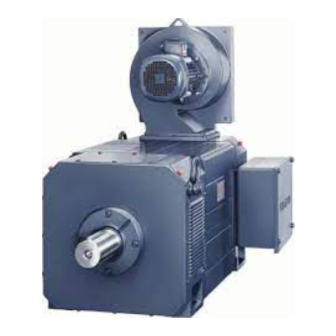
Motor description Properties Overview Air-cooled 1PH7 motors are rugged and low-maintenance 4-pole induction motors with squirrel-cage rotors. A fan for providing forced ventilation is mounted axially on the rear side of the motor. The air flow direction is as standard from the motor shaft (DE) to the rear of the motor (NDE) in order to keep the motor heat loss away from the machine. -
Page 18: Torque Overview
Motor description 1.1 Properties Area of application ● Compact machine tools ● Complex machining centers and lathes ● Customized machines ● Printing industry: – Single drives for printing units ● Rubber, plastics, wire and glass manufacturing: – Drives for extruders, calenders, rubber injection machines, foil machines, fleece machines –... -
Page 19: Technical Features
Motor description 1.2 Technical features Technical features Table 1- 1 Technical features Technical feature Version Motor type Induction motor Type of construction according to EN 60034–7 IM B3, IM B5, IM B35 (see selection and ordering data) (IEC 60034–7) Degree of protection acc. to EN 60034–5 IP55 (fan IP54) (IEC 60034–5) Cooling according to EN 60034–6 (IEC 60034–6) - Page 20 Motor description 1.2 Technical features Technical feature Version Shaft end to DIN 748–3 (IEC 60072–1) With keyway and feather key, plain shaft (see Selection and ordering data) Bearing version DE (standard) SH 100 to 160 for belt coupling and coupling Deep-groove ball bearings output: SH 180 to 225...
- Page 21 Motor description 1.2 Technical features Options Table 1- 2 Codes and option description Order code Option description For use with 1PH7 induction motors with shaft height SH 100 SH 180 SH 160 SH 225 Standard paint finish in another color, RAL ... ⃝...
-
Page 22: Selection And Ordering Data
Motor description 1.3 Selection and ordering data Selection and ordering data Shaft Rated Continuous speed, Speed, max. Rated power for duty type 1PH7 asynchronous motor height speed max. in accordance with IEC 60034-1 with solid shaft Forced ventilation Order No. rated S1 cont. - Page 23 Motor description 1.3 Selection and ordering data Motor type Rated Moment of Weight, Rated current SINAMICS S120 Motor Module (continued) torque inertia approx. for duty type Rated Booksize format in accordance with IEC 60034-1 output current Order No. rated rated rated S6-60% S6-40% S2- 30 min S1 -ft)
- Page 24 Motor description 1.3 Selection and ordering data Shaft Rated Continuous speed, Speed, max. Rated power for duty type 1PH7 asynchronous motor height speed max. in accordance with IEC 60034-1 with solid shaft Forced ventilation Order No. rated S1 cont. S1 cont. rated Standard type S6-60%...
- Page 25 Motor description 1.3 Selection and ordering data Motor type Rated Moment of Weight, Rated current SINAMICS S120 Motor Module (continued) torque inertia approx. for duty type Rated Booksize format in accordance with IEC 60034-1 output current Order No. rated rated rated S6-60% S6-40%...
- Page 26 Motor description 1.3 Selection and ordering data Shaft Rated Continuous speed, Speed, max. Rated power for duty type 1PH7 asynchronous motor height speed max. in accordance with IEC 60034-1 with solid shaft Forced ventilation Order No. rated S1 cont. S1 cont. rated Standard type S6-60%...
- Page 27 Motor description 1.3 Selection and ordering data Motor type Rated Moment of Weight, Rated current SINAMICS S120 Motor Module (continued) torque inertia approx. for duty type Rated Booksize format in accordance with IEC 60034-1 output current Order No. rated rated rated S6-60% S6-40% S2-30 min S1 -ft)
- Page 28 Motor description 1.3 Selection and ordering data Shaft Rated Continuous speed, Speed, max. Rated power for duty type 1PH7 asynchronous motor height speed max. in accordance with IEC 60034-1 with solid shaft Forced ventilation Order No. rated S1 cont. S1 cont. rated Standard type S6-60%...
- Page 29 Motor description 1.3 Selection and ordering data Motor type Rated Moment of Weight, Rated current SINAMICS S120 Motor Module (continued) torque inertia approx. for duty type Rated Booksize format in accordance with IEC 60034-1 output current Order No. rated rated rated S6-60% S6-40%...
- Page 30 Motor description 1.3 Selection and ordering data Shaft Rated Continuous speed, Speed, max. Rated power 1PH7 asynchronous motor height speed max. for duty type with solid shaft in accordance with IEC 60034-1 Forced ventilation Order No. rated S1 cont. S1 cont. S1 cont.
- Page 31 Motor description 1.3 Selection and ordering data Motor type Rated Moment of Weight, Rated current SINAMICS S120 Motor Module (continued) torque inertia approx. for duty type Rated Booksize format in accordance with IEC 60034-1 output current Order No. rated rated rated S6-60% S6-40%...
- Page 32 Motor description 1.3 Selection and ordering data Shaft Rated Continuous speed, Speed, max. Rated power 1PH7 asynchronous motor height speed max. for duty type with solid shaft in accordance with IEC 60034-1 Forced ventilation Order No. rated S1 cont. S1 cont. S1 cont.
- Page 33 Motor description 1.3 Selection and ordering data Motor type Rated Moment of Weight, Rated current SINAMICS S120 Motor Module (continued) torque inertia approx. for duty type Rated Booksize format in accordance with IEC 60034-1 output current Order No. rated rated rated S6-60% S6-40%...
- Page 34 Motor description 1.3 Selection and ordering data Shaft Rated Continuous speed, Speed, max. Rated power 1PH7 asynchronous motor height speed max. for duty type with solid shaft in accordance with IEC 60034-1 Forced ventilation Order No. rated S1 cont. S1 cont. S1 cont.
- Page 35 Motor description 1.3 Selection and ordering data Motor type Rated Moment of Weight, Rated current SINAMICS S120 Motor Module (continued) torque inertia approx. for duty type Rated Booksize format in accordance with IEC 60034-1 output current Order No. rated rated rated S6-60% S6-40%...
-
Page 36: Rating Plate Data
Motor description 1.4 Rating plate data Rating plate data The rating plate contains the technical specifications relevant to the motor. ϕ Figure 1-2 Schematic layout of rating plate 1PH7 induction motors (Machine tools) Configuration Manual, (APH7W), 04/2009, 6SN1197-0AD72-0BP0... - Page 37 Motor description 1.4 Rating plate data Table 1- 3 Elements on the rating plate Description Description Order number Rated speed n Consecutive number, part of serial number Operating mode (2) Serial number Code for operating point 2 UL approval Rated voltage V Graphical symbol zone 2 Switching mode 3 Type of construction...
- Page 38 Motor description 1.4 Rating plate data 1PH7 induction motors (Machine tools) Configuration Manual, (APH7W), 04/2009, 6SN1197-0AD72-0BP0...
-
Page 39: Configuration
Configuration Configuring software 2.1.1 SIZER engineering tool Overview Figure 2-1 SIZER The SIZER configuration tool provides an easy-to-use means of configuring the SINAMICS and MICROMASTER 4 drive families, as well as the SINUMERIK solution line CNC control and SIMOTION Motion Control system. It provides support for the technical planning of the hardware and firmware components required for a drive task. - Page 40 Configuration 2.1 Configuring software The SIZER user interface is available in German and English. The drive configuration is saved in a project. In the project, the components and functions used are displayed in a hierarchical tree structure. The project view permits the configuration of drive systems and the copying/inserting/modifying of drives already configured.
-
Page 41: Starter Drive/Commissioning Software
Select the country and then in the menu bar "Products". In the navigator, set "Drive Technology" → "Engineering software" → "STARTER drive/commissioning software" Download, refer under http://support.automation.siemens.com 2.1.3 SinuCom commissioning tool The simple-to-use commissioning software for PC/PG serves to ensure optimum commissioning of drives with SINAMICS S120/SIMODRIVE 611 digital. -
Page 42: Connection System
Configuration 2.2 SINAMICS procedure when engineering SINAMICS procedure when engineering Motion control Servo drives are optimized for motion control applications. They execute linear or rotary movements within a defined movement cycle. All movements should be optimized in terms of time. As a result of these considerations, servo drives must meet the following requirements: ●... -
Page 43: Selecting And Dimensioning Induction Motors
Configuration 2.3 Selecting and dimensioning induction motors Selecting and dimensioning induction motors 2.3.1 Clarification of the type of drive The motor is selected on the basis of the required torque, which is defined by the application, e.g. traveling drives, hoisting drives, test stands, centrifuges, paper and rolling mill drives, feed drives or main spindle drives. -
Page 44: Selecting Induction Motors
Configuration 2.3 Selecting and dimensioning induction motors 2.3.3 Selecting induction motors A differentiation must be made between 3 applications when selecting a suitable induction motor: Case 1: The motor essentially operates in continuous duty. Case 2: A periodic duty cycle determines how the drive is dimensioned. Case 3: A high field weakening range is required. -
Page 45: Motor Operates With A Periodic Duty Cycle
Configuration 2.3 Selecting and dimensioning induction motors 2.3.5 Motor operates with a periodic duty cycle The duty cycle determines how the drive is dimensioned. It is assumed that the speeds during the duty cycle lie below the rated speed. If the power is known, but the torques during the duty cycle are unknown, then the power must be converted to a torque: M = P ∙... -
Page 46: A High Field Weakening Range Is Required
Configuration 2.3 Selecting and dimensioning induction motors Motor selection Table 2- 3 The motor is selected depending on the cycle duration and the thermal time constant Cycle duration Motor selection ≤ 0.1 (cycle duration of 2 to 4 min) A motor with the following rated torque M should be selected: >... - Page 47 Configuration 2.3 Selecting and dimensioning induction motors Figure 2-3 Motor selection based on power-speed and torque-speed diagrams Example of the calculation of n A specific power of P = 8 kW is required at n = 5250 rpm. The field weakening range should be 1 : 3.5. Calculation of the required rated speed n : 5250 / 3.5 rpm = 1500 rpm.
- Page 48 Configuration 2.3 Selecting and dimensioning induction motors 1PH7 induction motors (Machine tools) Configuration Manual, (APH7W), 04/2009, 6SN1197-0AD72-0BP0...
-
Page 49: Mechanical Properties Of The Motors
0.86 2500 0.90 0.86 0.83 3000 0.86 0.82 0.79 3500 0.82 0.79 0.75 4000 0.77 0.74 0.71 NOTICE For ambient temperatures > 50 °C, please contact your local Siemens office. 1PH7 induction motors (Machine tools) Configuration Manual, (APH7W), 04/2009, 6SN1197-0AD72-0BP0... - Page 50 Mechanical properties of the motors 3.1 Cooling Mounting a fan and minimum clearance to the customers mounted parts and components Table 3- 2 Fan mounting Shaft height [mm] Fan mounting 100 to 225 NDE axial, can be rotated through 4 x 90° The minimum clearance to the customer's mounted parts and components and the air discharge opening as well as the minimum clearance S between the air intake and air discharge openings and adjacent components must be maintained.
- Page 51 Mechanical properties of the motors 3.1 Cooling Cleaning the cooling air passages For air-cooled motors, the cooling ducts, through which the ambient air flows, must be regularly cleaned depending on the degree of pollution at the mounting location. These air ducts can be cleaned, e.g.
-
Page 52: Degree Of Protection Acc. To En 60034-5
Mechanical properties of the motors 3.2 Degree of protection acc. to EN 60034-5 Degree of protection acc. to EN 60034-5 Degree of protection designation The degree of protection designation in accordance with EN 60034-5 (IEC 60034-5) is described using the letters "IP" and two digits (e.g. IP64). IP = International Protection 1st digit = protection against ingress of foreign bodies 2nd digit = protection against harmful ingress of water... -
Page 53: Bearing Version
Mechanical properties of the motors 3.3 Bearing version Bearing version 3.3.1 Drive output types and bearing versions 1PH7 induction motors are suitable for coupling output and belt coupling. The bearing versions and their applications are summarized in the following table. Table 3- 5 Drive output type with the appropriate bearing design Application... - Page 54 Mechanical properties of the motors 3.3 Bearing version Output type, bearing version and maximum speed Table 3- 6 Output type, bearing version and maximum speed Shaft height Bearing type/ Bearings on Bearing Max. continuous Max. speed limit drive output type the motor designation speed for S1 duty...
-
Page 55: Bearing Lifetime
Mechanical properties of the motors 3.3 Bearing version 3.3.2 Bearing lifetime The bearing lifetime is limited by material fatigue (fatigue lifetime) or lubrication failure (grease lifetime). The fatigue lifetime (statistical bearing lifetime L ) is mainly dependent on the mechanical load. The inter-dependency is shown in the radial force/axial force diagrams. The values are determined according to DIN/ISO 281. - Page 56 Mechanical properties of the motors 3.3 Bearing version Table 3- 7 Recommended bearing change intervals (standard bearing design) Shaft Drive output type Average Stat. bearing Recommended bearing change interval height operating speed lifetime [rpm] Permanent Regreasing lubrication Coupling output or ≤...
- Page 57 Mechanical properties of the motors 3.3 Bearing version Regreasing For motors which can be re-lubricated at defined re-lubricating intervals, the bearing lifetime can be extended and/or unfavorable factors such as mounting conditions, speed, bearing size and mechanical load can be compensated (refer to the table "Recommended bearing change intervals (standard bearing design)").
- Page 58 Mechanical properties of the motors 3.3 Bearing version Table 3- 10 Regreasing intervals Shaft Bearing type/ Bearing- Bearing Re-lubricating Quantity of Grease Possible height drive output type type designa- intervals in grease for chamber number of re- motor tion operating each lubricating side...
-
Page 59: Radial And Axial Forces
The force diagrams and tables only apply to the standard shaft ends at the DE. For smaller shaft diameters, only reduced radial forces may be transmitted or none at all. For force levels going beyond these, please contact your local Siemens office. CAUTION... - Page 60 Mechanical properties of the motors 3.4 Radial and axial forces Note The radial forces at the shaft end must be precisely dimensioned according to the guidelines specified by the belt manufacturer. The belt tension must be adjusted using the appropriate measuring equipment.
-
Page 61: Radial Force Diagrams
Mechanical properties of the motors 3.4 Radial and axial forces 3.4.2 Radial force diagrams SH 100, permissible radial forces for a standard bearing design Figure 3-1 Radial force diagram, SH 100 for standard bearing designs 1PH7 induction motors (Machine tools) Configuration Manual, (APH7W), 04/2009, 6SN1197-0AD72-0BP0... - Page 62 Mechanical properties of the motors 3.4 Radial and axial forces SH 100, permissible radial forces for increased max. speed Figure 3-2 Radial force diagram, SH 100 for increased max. speed 1PH7 induction motors (Machine tools) Configuration Manual, (APH7W), 04/2009, 6SN1197-0AD72-0BP0...
- Page 63 Mechanical properties of the motors 3.4 Radial and axial forces SH 132, permissible radial forces for a standard bearing design Figure 3-3 Radial force diagram, SH 132 for standard bearing designs 1PH7 induction motors (Machine tools) Configuration Manual, (APH7W), 04/2009, 6SN1197-0AD72-0BP0...
- Page 64 Mechanical properties of the motors 3.4 Radial and axial forces SH 132, permissible radial forces for increased max. speed Figure 3-4 Radial force diagram, SH 132 for increased max. speed 1PH7 induction motors (Machine tools) Configuration Manual, (APH7W), 04/2009, 6SN1197-0AD72-0BP0...
- Page 65 Mechanical properties of the motors 3.4 Radial and axial forces SH 160, permissible radial forces for a standard bearing design Figure 3-5 Radial force diagram, SH 160 for standard bearing designs 1PH7 induction motors (Machine tools) Configuration Manual, (APH7W), 04/2009, 6SN1197-0AD72-0BP0...
- Page 66 Mechanical properties of the motors 3.4 Radial and axial forces SH 160, permissible radial forces for increased max. speed Figure 3-6 Radial force diagram, SH 160 for increased max. speed 1PH7 induction motors (Machine tools) Configuration Manual, (APH7W), 04/2009, 6SN1197-0AD72-0BP0...
- Page 67 Mechanical properties of the motors 3.4 Radial and axial forces SH 180, permissible radial forces for a coupling output Figure 3-7 Radial force diagram, SH 180 for coupling output 1PH7 induction motors (Machine tools) Configuration Manual, (APH7W), 04/2009, 6SN1197-0AD72-0BP0...
- Page 68 Mechanical properties of the motors 3.4 Radial and axial forces SH 180, permissible radial forces for belt couplings Figure 3-8 Radial force diagram, SH 180 for belt couplings 1PH7 induction motors (Machine tools) Configuration Manual, (APH7W), 04/2009, 6SN1197-0AD72-0BP0...
- Page 69 Mechanical properties of the motors 3.4 Radial and axial forces SH 180, permissible increased radial forces for belt couplings Figure 3-9 Radial force diagram, SH 180 for belt couplings (increased radial forces) 1PH7 induction motors (Machine tools) Configuration Manual, (APH7W), 04/2009, 6SN1197-0AD72-0BP0...
- Page 70 Mechanical properties of the motors 3.4 Radial and axial forces SH 225, permissible radial forces for a coupling output Figure 3-10 Radial force diagram, SH 225 for coupling output 1PH7 induction motors (Machine tools) Configuration Manual, (APH7W), 04/2009, 6SN1197-0AD72-0BP0...
- Page 71 Mechanical properties of the motors 3.4 Radial and axial forces SH 225, permissible radial forces for belt couplings Figure 3-11 Radial force diagram, SH 225 for belt couplings 1PH7 induction motors (Machine tools) Configuration Manual, (APH7W), 04/2009, 6SN1197-0AD72-0BP0...
- Page 72 Mechanical properties of the motors 3.4 Radial and axial forces SH 225, permissible increased radial forces for belt couplings Figure 3-12 Radial force diagram, SH 225 for belt couplings (increased radial forces) 1PH7 induction motors (Machine tools) Configuration Manual, (APH7W), 04/2009, 6SN1197-0AD72-0BP0...
-
Page 73: Axial Force
Mechanical properties of the motors 3.4 Radial and axial forces 3.4.3 Axial force The axial force acting on the bearings comprises an external axial force (e.g. gearbox with helical gearing, machining forces through the tool), a bearing pre-load force and possibly the force due to the weight of the rotor when the motor is vertically mounted. -
Page 74: Axial Force Diagrams
Mechanical properties of the motors 3.4 Radial and axial forces Forces due to weight of the rotor and pre-loading forces of the rotor Table 3- 13 Forces due to the weight of the rotor F and pre-loading forces F of the rotor Motor type 1PH7101 1PH7103... - Page 75 Mechanical properties of the motors 3.4 Radial and axial forces SH 100, permissible axial force Figure 3-13 Axial force diagram, SH 100 SH 132, permissible axial force Figure 3-14 Axial force diagram, SH 132 1PH7 induction motors (Machine tools) Configuration Manual, (APH7W), 04/2009, 6SN1197-0AD72-0BP0...
- Page 76 Mechanical properties of the motors 3.4 Radial and axial forces SH 160, permissible axial force Figure 3-15 Axial force diagram, SH 160 1PH7 induction motors (Machine tools) Configuration Manual, (APH7W), 04/2009, 6SN1197-0AD72-0BP0...
- Page 77 Mechanical properties of the motors 3.4 Radial and axial forces SH 100, permissible axial force for the option, increased max. speed Figure 3-16 Cantilever force diagram, SH 100 (increased max. speed) SH 132, permissible axial force for the option, increased max. speed Figure 3-17 Cantilever force diagram, SH 132 (increased max.
- Page 78 (i.e. low vibration): ● SH 180: max. 500 N ● SH 225: max. 600 N For pinion outputs with helical gearing, please contact your local Siemens office. 1PH7 induction motors (Machine tools) Configuration Manual, (APH7W), 04/2009, 6SN1197-0AD72-0BP0...
-
Page 79: Shaft End And Balancing
Mechanical properties of the motors 3.5 Shaft end and balancing Shaft end and balancing The drive shaft end is cylindrical in accordance with DIN 748 Part 3 (IEC 60072-1). Standard: Keyway with feather key (half-key balancing) The motor balance quality is certified in accordance with DIN ISO 8821. 1PH7 induction motors (Machine tools) Configuration Manual, (APH7W), 04/2009, 6SN1197-0AD72-0BP0... -
Page 80: Radial Eccentricity, Concentricity And Axial Eccentricity
Mechanical properties of the motors 3.6 Radial eccentricity, concentricity and axial eccentricity Radial eccentricity, concentricity and axial eccentricity The shaft and flange accuracies are checked according to DIN 42955, IEC 60072. Data deviating from these values are indicated in the dimension drawings. Table 3- 14 Radial eccentricity tolerance of the shaft to the frame axis (referred to cylindrical shaft ends) -
Page 81: Balancing Process
Mechanical properties of the motors 3.7 Balancing process Figure 3-20 Checking the concentricity and axial eccentricity Balancing process Requirements placed on the process when balancing mounted components - especially belt pulleys In addition to the balance quality of the motor, the vibration quality of motors with mounted belt pulleys and coupling is essentially determined by the balance quality of the mounted component. - Page 82 Mechanical properties of the motors 3.7 Balancing process Table 3- 16 Requirements placed on the balancing process as a function of the motor balancing type Balancing equipment/ Motor Motor balanced with full key Motor with plain Process step Half key balanced shaft end Auxiliary shaft with Auxiliary shaft with...
-
Page 83: Vibration Severity Level
Mechanical properties of the motors 3.8 Vibration severity level Vibration severity level The 1PH7 motors conform to vibration severity level A in accordance with EN 60034-14 (IEC 60034-14). The values indicated refer only to the motor. These values can be increased at the motor due to the overall vibration characteristics of the complete system after the drive has been mounted. -
Page 84: Paint Finish
Mechanical properties of the motors 3.9 Paint finish Figure 3-22 Vibration severity limit values for induction motors SH 160 to 225 Paint finish 1PH7 motors are supplied with the following paint finish: ● SH 100 to 160: Without paint finish or standard paint finish, anthracite RAL 7016 ●... -
Page 85: Technical Data And Characteristics
Technical data and characteristics Mode of operation and characteristics A constant torque M is available from standstill up to the rated operating point. The constant-power range begins from the rated operating point (see P/n characteristic). Induction motors have a high overload capacity in the constant power range. For some induction motors, the overload capacity is reduced in the highest speed range. -
Page 86: Output Voltages
Technical data and characteristics 4.2 Output voltages Power rating data for duty types S1 and S6 All power rating data of induction motors refer to continuous operation and the appropriate duty type S1. However, for many applications, duty type S1 does not apply, if e.g. the load varies as a function of time. -
Page 87: Offset Of The Voltage Limit Characteristic
Technical data and characteristics 4.3 Offset of the voltage limit characteristic Offset of the voltage limit characteristic The characteristics in chapter "P/n and M/n characteristics" refer to the Active Line Module, = 400 V. The output voltage U is 425 V. supply In order to identify the motor limits with an output voltage other than 425 V, the plotted voltage limiting characteristic must be shifted accordingly for the new output voltage. - Page 88 Technical data and characteristics 4.3 Offset of the voltage limit characteristic Figure 4-2 An example of the offset in the voltage limiting characteristic 1PH7 induction motors (Machine tools) Configuration Manual, (APH7W), 04/2009, 6SN1197-0AD72-0BP0...
-
Page 89: P/N And M/N Characteristics
Technical data and characteristics 4.4 P/n and M/n characteristics P/n and M/n characteristics 4.4.1 Explanation of the abbreviations used Irrespective of the operating mode, running motors must be cooled continuously. Table 4- 2 Explanation of abbreviations in the following tables Abbreviation Unit Description... - Page 90 Technical data and characteristics 4.4 P/n and M/n characteristics Table 4- 3 SINAMICS, 3-ph. 400 V AC, Servo Control, (ALM), 1PH7101-☐☐F☐☐ μ [rpm] [kW] [Nm] [Hz] [rpm] [rpm] [min] 1500 23.6 10.0 51.6 8234 9000 20.0 Briefly: For continuous operation (with 30 % n , 60 % 2/3 n , 10 % standstill) for a duty cycle duration of 10 min.
- Page 91 Technical data and characteristics 4.4 P/n and M/n characteristics Table 4- 4 SINAMICS, 3-ph. 400 V AC, Servo Control, (ALM), 1PH7101-☐☐F☐☐-0L μ [rpm] [kW] [Nm] [Hz] [rpm] [rpm] [min] 1500 51.6 8234 12000 20.0 Briefly: For continuous operation (with 30 % n , 60 % 2/3 n , 10 % standstill) for a duty cycle duration of 10 min.
- Page 92 Technical data and characteristics 4.4 P/n and M/n characteristics Table 4- 5 SINAMICS, 3-ph. 400 V AC, Servo Control, (ALM), 1PH7103-☐☐D☐☐ μ [rpm] [kW] [Nm] [Hz] [rpm] [rpm] [min] 1000 35.3 10.0 35.6 3750 9000 20.0 Briefly: For continuous operation (with 30 % n , 60 % 2/3 n , 10 % standstill) for a duty cycle duration of 10 min.
- Page 93 Technical data and characteristics 4.4 P/n and M/n characteristics Table 4- 6 SINAMICS, 3-ph. 400 V AC, Servo Control, (ALM), 1PH7103-☐☐D☐☐-0L μ [rpm] [kW] [Nm] [Hz] [rpm] [rpm] [min] 1000 35.6 3750 12000 20.0 Briefly: For continuous operation (with 30 % n , 60 % 2/3 n , 10 % standstill) for a duty cycle duration of 10 min.
- Page 94 Technical data and characteristics 4.4 P/n and M/n characteristics Table 4- 7 SINAMICS, 3-ph. 400 V AC, Servo Control (ALM), 1PH7103-☐☐F☐☐ μ [rpm] [kW] [Nm] [Hz] [rpm] [rpm] [min] 1500 35.0 13.0 52.7 5000 9000 26.0 Briefly: For continuous operation (with 30 % n , 60 % 2/3 n , 10 % standstill) for a duty cycle duration of 10 min.
- Page 95 Technical data and characteristics 4.4 P/n and M/n characteristics Table 4- 8 SINAMICS, 3-ph. 400 V AC, Servo Control, (ALM), 1PH7103-☐☐F☐☐-0L μ [rpm] [kW] [Nm] [Hz] [rpm] [rpm] [min] 1500 52.7 5000 12000 26.0 Briefly: For continuous operation (with 30 % n , 60 % 2/3 n , 10 % standstill) for a duty cycle duration of 10 min.
- Page 96 Technical data and characteristics 4.4 P/n and M/n characteristics Table 4- 9 SINAMICS, 3-ph. 400 V AC, Servo Control (ALM), 1PH7103-☐☐G☐☐ μ [rpm] [kW] [Nm] [Hz] [rpm] [rpm] [min] 2000 33.4 17.5 68.9 9000 9000 35.0 Briefly: For continuous operation (with 30 % n , 60 % 2/3 n , 10 % standstill) for a duty cycle duration of 10 min.
- Page 97 Technical data and characteristics 4.4 P/n and M/n characteristics Table 4- 10 SINAMICS, 3-ph. 400 V AC, Servo Control (ALM), 1PH7103-☐☐G☐☐-0L μ [rpm] [kW] [Nm] [Hz] [rpm] [rpm] [min] 2000 17.5 68.9 7000 12000 35.0 Briefly: For continuous operation (with 30 % n , 60 % 2/3 n , 10 % standstill) for a duty cycle duration of 10 min.
- Page 98 Technical data and characteristics 4.4 P/n and M/n characteristics Table 4- 11 SINAMICS, 3-ph. 400 V AC, Servo Control, (ALM), 1PH7105-☐☐F☐☐ μ [rpm] [kW] [Nm] [Hz] [rpm] [rpm] [min] 1500 44.6 17.5 51.7 7941 9000 35.0 Briefly: For continuous operation (with 30 % n , 60 % 2/3 n , 10 % standstill) for a duty cycle duration of 10 min.
- Page 99 Technical data and characteristics 4.4 P/n and M/n characteristics Table 4- 12 SINAMICS, 3-ph. 400 V AC, Servo Control, (ALM), 1PH7105-☐☐F☐☐-0L μ [rpm] [kW] [Nm] [Hz] [rpm] [rpm] [min] 1500 17.5 51.7 7941 12000 35.0 Briefly: For continuous operation (with 30 % n , 60 % 2/3 n , 10 % standstill) for a duty cycle duration of 10 min.
- Page 100 Technical data and characteristics 4.4 P/n and M/n characteristics Table 4- 13 SINAMICS, 3-ph. 400 V AC, Servo Control (ALM), 1PH7107-☐☐D☐☐ μ [rpm] [kW] [Nm] [Hz] [rpm] [rpm] [min] 1000 59.7 17.5 35.3 5783 9000 35.0 Briefly: For continuous operation (with 30 % n , 60 % 2/3 n , 10 % standstill) for a duty cycle duration of 10 min.
- Page 101 Technical data and characteristics 4.4 P/n and M/n characteristics Table 4- 14 SINAMICS, 3-ph. 400 V AC, Servo Control, (ALM), 1PH7107-☐☐D☐☐-0L μ [rpm] [kW] [Nm] [Hz] [rpm] [rpm] [min] 1000 6.25 17.5 35.3 5783 12000 35.0 Briefly: For continuous operation (with 30 % n , 60 % 2/3 n , 10 % standstill) for a duty cycle duration of 10 min.
- Page 102 Technical data and characteristics 4.4 P/n and M/n characteristics Table 4- 15 SINAMICS, 3-ph. 400 V AC, Servo Control (ALM), 1PH7107-☐☐F☐☐ μ [rpm] [kW] [Nm] [Hz] [rpm] [rpm] [min] 1500 57.3 23.5 52.0 6500 9000 11.0 47.0 Briefly: For continuous operation (with 30 % n , 60 % 2/3 n , 10 % standstill) for a duty cycle duration of 10 min.
- Page 103 Technical data and characteristics 4.4 P/n and M/n characteristics Table 4- 16 SINAMICS, 3-ph. 400 V AC, Servo Control, (ALM), 1PH7107-☐☐F☐☐-0L μ [rpm] [kW] [Nm] [Hz] [rpm] [rpm] [min] 1500 23.5 52.0 5500 12000 11.0 47.0 Briefly: For continuous operation (with 30 % n , 60 % 2/3 n , 10 % standstill) for a duty cycle duration of 10 min.
- Page 104 Technical data and characteristics 4.4 P/n and M/n characteristics Table 4- 17 SINAMICS, 3-ph. 400 V AC, Servo Control (ALM), 1PH7107-☐☐G☐☐ μ [rpm] [kW] [Nm] [Hz] [rpm] [rpm] [min] 2000 10.5 50.1 26.0 68.6 7000 9000 12.0 52.0 Briefly: For continuous operation (with 30 % n , 60 % 2/3 n , 10 % standstill) for a duty cycle duration of 10 min.
- Page 105 Technical data and characteristics 4.4 P/n and M/n characteristics Table 4- 18 SINAMICS, 3-ph. 400 V AC, Servo Control (ALM), 1PH7107-☐☐G☐☐-0L μ [rpm] [kW] [Nm] [Hz] [rpm] [rpm] [min] 2000 10.5 68.6 7000 12000 12.0 52.0 Briefly: For continuous operation (with 30 % n , 60 % 2/3 n , 10 % standstill) for a duty cycle duration of 10 min.
- Page 106 Technical data and characteristics 4.4 P/n and M/n characteristics Table 4- 19 SINAMICS, 3-ph. 400 V AC, Servo Control (ALM), 1PH7131-☐☐F☐☐ μ [rpm] [kW] [Nm] [Hz] [rpm] [rpm] [min] 1500 51.3 6660 8000 Briefly: For continuous operation (with 30 % n , 60 % 2/3 n , 10 % standstill) for a duty cycle duration of 10 min.
- Page 107 Technical data and characteristics 4.4 P/n and M/n characteristics Table 4- 20 SINAMICS, 3-ph. 400 V AC, Servo Control, (ALM), 1PH7131-☐☐F☐☐-0L μ [rpm] [kW] [Nm] [Hz] [rpm] [rpm] [min] 1500 51.3 6660 10000 Briefly: For continuous operation (with 30 % n , 60 % 2/3 n , 10 % standstill) for a duty cycle duration of 10 min.
- Page 108 Technical data and characteristics 4.4 P/n and M/n characteristics Table 4- 21 SINAMICS, 3-ph. 400 V AC, Servo Control (ALM), 1PH7133-☐☐D☐☐ μ [rpm] [kW] [Nm] [Hz] [rpm] [rpm] [min] 1000 34.8 4695 8000 Briefly: For continuous operation (with 30 % n , 60 % 2/3 n , 10 % standstill) for a duty cycle duration of 10 min.
- Page 109 Technical data and characteristics 4.4 P/n and M/n characteristics Table 4- 22 SINAMICS, 3-ph. 400 V AC, Servo Control, (ALM), 1PH7133-☐☐D☐☐-0L μ [rpm] [kW] [Nm] [Hz] [rpm] [rpm] [min] 1000 34.8 4695 10000 Briefly: For continuous operation (with 30 % n , 60 % 2/3 n , 10 % standstill) for a duty cycle duration of 10 min.
- Page 110 Technical data and characteristics 4.4 P/n and M/n characteristics Table 4- 23 SINAMICS, 3-ph. 400 V AC, Servo Control (ALM), 1PH7133-☐☐F☐☐ μ [rpm] [kW] [Nm] [Hz] [rpm] [rpm] [min] 1500 51.3 6854 8000 Briefly: For continuous operation (with 30 % n , 60 % 2/3 n , 10 % standstill) for a duty cycle duration of 10 min.
- Page 111 Technical data and characteristics 4.4 P/n and M/n characteristics Table 4- 24 SINAMICS, 3-ph. 400 V AC, Servo Control, (ALM), 1PH7133-☐☐F☐☐-0L μ [rpm] [kW] [Nm] [Hz] [rpm] [rpm] [min] 1000 51.3 6000 10000 Briefly: For continuous operation (with 30 % n , 60 % 2/3 n , 10 % standstill) for a duty cycle duration of 10 min.
- Page 112 Technical data and characteristics 4.4 P/n and M/n characteristics Table 4- 25 SINAMICS, 3-ph. 400 V AC, Servo Control (ALM), 1PH7133-☐☐G☐☐ μ [rpm] [kW] [Nm] [Hz] [rpm] [rpm] [min] 2000 68.0 6500 8000 Briefly: For continuous operation (with 30 % n , 60 % 2/3 n , 10 % standstill) for a duty cycle duration of 10 min.
- Page 113 Technical data and characteristics 4.4 P/n and M/n characteristics Table 4- 26 SINAMICS, 3-ph. 400 V AC, Servo Control (ALM), 1PH7133-☐☐G☐☐-0L μ [rpm] [kW] [Nm] [Hz] [rpm] [rpm] [min] 2000 68.0 6000 10000 Briefly: For continuous operation (with 30 % n , 60 % 2/3 n , 10 % standstill) for a duty cycle duration of 10 min.
- Page 114 Technical data and characteristics 4.4 P/n and M/n characteristics Table 4- 27 SINAMICS, 3-ph. 400 V AC, Servo Control (ALM), 1PH7135-☐☐F☐☐ μ [rpm] [kW] [Nm] [Hz] [rpm] [rpm] [min] 1500 18.5 51.1 7537 8000 Briefly: For continuous operation (with 30 % n , 60 % 2/3 n , 10 % standstill) for a duty cycle duration of 10 min.
- Page 115 Technical data and characteristics 4.4 P/n and M/n characteristics Table 4- 28 SINAMICS, 3-ph. 400 V AC, Servo Control, (ALM), 1PH7135-☐☐F☐☐-0L μ [rpm] [kW] [Nm] [Hz] [rpm] [rpm] [min] 1500 18.5 51.1 7537 10000 Briefly: For continuous operation (with 30 % n , 60 % 2/3 n , 10 % standstill) for a duty cycle duration of 10 min.
- Page 116 Technical data and characteristics 4.4 P/n and M/n characteristics Table 4- 29 SINAMICS, 3-ph. 400 V AC, Servo Control (ALM), 1PH7137-☐☐D☐☐ μ [rpm] [kW] [Nm] [Hz] [rpm] [rpm] [min] 1000 34.6 5403 8000 Briefly: For continuous operation (with 30 % n , 60 % 2/3 n , 10 % standstill) for a duty cycle duration of 10 min.
- Page 117 Technical data and characteristics 4.4 P/n and M/n characteristics Table 4- 30 SINAMICS, 3-ph. 400 V AC, Servo Control, (ALM), 1PH7137-☐☐D☐☐-0L μ [rpm] [kW] [Nm] [Hz] [rpm] [rpm] [min] 1000 34.6 5403 10000 Briefly: For continuous operation (with 30 % n , 60 % 2/3 n , 10 % standstill) for a duty cycle duration of 10 min.
- Page 118 Technical data and characteristics 4.4 P/n and M/n characteristics Table 4- 31 SINAMICS, 3-ph. 400 V AC, Servo Control (ALM), 1PH7137-☐☐F☐☐ μ [rpm] [kW] [Nm] [Hz] [rpm] [rpm] [min] 1500 51.2 7000 8000 22.8 Briefly: For continuous operation (with 30 % n , 60 % 2/3 n , 10 % standstill) for a duty cycle duration of 10 min.
- Page 119 Technical data and characteristics 4.4 P/n and M/n characteristics Table 4- 32 SINAMICS, 3-ph. 400 V AC, Servo Control, (ALM), 1PH7137-☐☐F☐☐-0L μ [rpm] [kW] [Nm] [Hz] [rpm] [rpm] [min] 1500 51.2 6500 10000 22.8 Briefly: For continuous operation (with 30 % n , 60 % 2/3 n , 10 % standstill) for a duty cycle duration of 10 min.
- Page 120 Technical data and characteristics 4.4 P/n and M/n characteristics Table 4- 33 SINAMICS, 3-ph. 400 V AC, Servo Control (ALM), 1PH7137-☐☐G☐☐ μ [rpm] [kW] [Nm] [Hz] [rpm] [rpm] [min] 2000 68.0 6000 8000 Briefly: For continuous operation (with 30 % n , 60 % 2/3 n , 10 % standstill) for a duty cycle duration of 10 min.
- Page 121 Technical data and characteristics 4.4 P/n and M/n characteristics Table 4- 34 SINAMICS, 3-ph. 400 V AC, Servo Control (ALM), 1PH7137-☐☐G☐☐-0L μ [rpm] [kW] [Nm] [Hz] [rpm] [rpm] [min] 2000 68.0 5000 10000 Briefly: For continuous operation (with 30 % n , 60 % 2/3 n , 10 % standstill) for a duty cycle duration of 10 min.
- Page 122 Technical data and characteristics 4.4 P/n and M/n characteristics Table 4- 35 SINAMICS, 3-ph. 400 V AC, Servo Control (ALM), 1PH7163-☐☐B☐☐ μ [rpm] [kW] [Nm] [Hz] [rpm] [rpm] [min] 14.3 1943 6500 11.5 Briefly: For continuous operation (with 30 % n , 60 % 2/3 n , 10 % standstill) for a duty cycle duration of 10 min.
- Page 123 Technical data and characteristics 4.4 P/n and M/n characteristics Table 4- 36 SINAMICS, 3-ph. 400 V AC, Servo Control (ALM), 1PH7163-☐☐B☐☐-0L μ [rpm] [kW] [Nm] [Hz] [rpm] [rpm] [min] 17.6 2487 8000 11.5 Briefly: For continuous operation (with 30 % n , 60 % 2/3 n , 10 % standstill) for a duty cycle duration of 10 min.
- Page 124 Technical data and characteristics 4.4 P/n and M/n characteristics Table 4- 37 SINAMICS, 3-ph. 400 V AC, Servo Control (ALM), 1PH7163-☐☐D☐☐ μ [rpm] [kW] [Nm] [Hz] [rpm] [rpm] [min] 1000 34.2 5871 6500 24.0 Briefly: For continuous operation (with 30 % n , 60 % 2/3 n , 10 % standstill) for a duty cycle duration of 10 min.
- Page 125 Technical data and characteristics 4.4 P/n and M/n characteristics Table 4- 38 SINAMICS, 3-ph. 400 V AC, Servo Control, (ALM), 1PH7163-☐☐D☐☐-0L μ [rpm] [kW] [Nm] [Hz] [rpm] [rpm] [min] 1000 32.2 4000 8000 Briefly: For continuous operation (with 30 % n , 60 % 2/3 n , 10 % standstill) for a duty cycle duration of 10 min.
- Page 126 Technical data and characteristics 4.4 P/n and M/n characteristics Table 4- 39 SINAMICS, 3-ph. 400 V AC, Servo Control (ALM), 1PH7163-☐☐F☐☐ μ [rpm] [kW] [Nm] [Hz] [rpm] [rpm] [min] 1500 30.0 50.9 5500 6500 Briefly: For continuous operation (with 30 % n , 60 % 2/3 n , 10 % standstill) for a duty cycle duration of 10 min.
- Page 127 Technical data and characteristics 4.4 P/n and M/n characteristics Table 4- 40 SINAMICS, 3-ph. 400 V AC, Servo Control, (ALM), 1PH7163-☐☐F☐☐-0L μ [rpm] [kW] [Nm] [Hz] [rpm] [rpm] [min] 1500 50.9 5000 8000 Briefly: For continuous operation (with 30 % n , 60 % 2/3 n , 10 % standstill) for a duty cycle duration of 10 min.
- Page 128 Technical data and characteristics 4.4 P/n and M/n characteristics Table 4- 41 SINAMICS, 3-ph. 400 V AC, Servo Control (ALM), 1PH7163-☐☐G☐☐ μ [rpm] [kW] [Nm] [Hz] [rpm] [rpm] [min] 2000 67.5 3500 6500 Briefly: For continuous operation (with 30 % n , 60 % 2/3 n , 10 % standstill) for a duty cycle duration of 10 min.
- Page 129 Technical data and characteristics 4.4 P/n and M/n characteristics Table 4- 42 SINAMICS, 3-ph. 400 V AC, Servo Control (ALM), 1PH7163-☐☐G☐☐-0L μ [rpm] [kW] [Nm] [Hz] [rpm] [rpm] [min] 2000 67.5 3500 8000 Briefly: For continuous operation (with 30 % n , 60 % 2/3 n , 10 % standstill) for a duty cycle duration of 10 min.
- Page 130 Technical data and characteristics 4.4 P/n and M/n characteristics Table 4- 43 SINAMICS, 3-ph. 400 V AC, Servo Control (ALM), 1PH7167-☐☐B☐☐ μ [rpm] [kW] [Nm] [Hz] [rpm] [rpm] [min] 14.3 2065 6500 Briefly: For continuous operation (with 30 % n , 60 % 2/3 n , 10 % standstill) for a duty cycle duration of 10 min.
- Page 131 Technical data and characteristics 4.4 P/n and M/n characteristics Table 4- 44 SINAMICS, 3-ph. 400 V AC, Servo Control (ALM), 1PH7167-☐☐B☐☐-0L μ [rpm] [kW] [Nm] [Hz] [rpm] [rpm] [min] 14.3 2065 8000 Briefly: For continuous operation (with 30 % n , 60 % 2/3 n , 10 % standstill) for a duty cycle duration of 10 min.
- Page 132 Technical data and characteristics 4.4 P/n and M/n characteristics Table 4- 45 SINAMICS, 3-ph. 400 V AC, Servo Control (ALM), 1PH7167-☐☐D☐☐ μ [rpm] [kW] [Nm] [Hz] [rpm] [rpm] [min] 1000 34.2 6239 6500 Briefly: For continuous operation (with 30 % n , 60 % 2/3 n , 10 % standstill) for a duty cycle duration of 10 min.
- Page 133 Technical data and characteristics 4.4 P/n and M/n characteristics Table 4- 46 SINAMICS, 3-ph. 400 V AC, Servo Control, (ALM), 1PH7167-☐☐D☐☐-0L μ [rpm] [kW] [Nm] [Hz] [rpm] [rpm] [min] 1000 3.42 5000 8000 Briefly: For continuous operation (with 30 % n , 60 % 2/3 n , 10 % standstill) for a duty cycle duration of 10 min.
- Page 134 Technical data and characteristics 4.4 P/n and M/n characteristics Table 4- 47 SINAMICS, 3-ph. 400 V AC, Servo Control (ALM), 1PH7167-☐☐F☐☐ μ [rpm] [kW] [Nm] [Hz] [rpm] [rpm] [min] 1500 50.8 4500 6500 Briefly: For continuous operation (with 30 % n , 60 % 2/3 n , 10 % standstill) for a duty cycle duration of 10 min.
- Page 135 Technical data and characteristics 4.4 P/n and M/n characteristics Table 4- 48 SINAMICS, 3-ph. 400 V AC, Servo Control, (ALM), 1PH7167-☐☐F☐☐-0L μ [rpm] [kW] [Nm] [Hz] [rpm] [rpm] [min] 1500 50.8 4000 8000 Briefly: For continuous operation (with 30 % n , 60 % 2/3 n , 10 % standstill) for a duty cycle duration of 10 min.
- Page 136 Technical data and characteristics 4.4 P/n and M/n characteristics Table 4- 49 SINAMICS, 3-ph. 400 V AC, Servo Control (ALM), 1PH7167-☐☐G☐☐ μ [rpm] [kW] [Nm] [Hz] [rpm] [rpm] [min] 2000 67.4 3250 6500 Briefly: For continuous operation (with 30 % n , 60 % 2/3 n , 10 % standstill) for a duty cycle duration of 10 min.
- Page 137 Technical data and characteristics 4.4 P/n and M/n characteristics Table 4- 50 SINAMICS, 3-ph. 400 V AC, Servo Control (ALM), 1PH7167-☐☐G☐☐-0L μ [rpm] [kW] [Nm] [Hz] [rpm] [rpm] [min] 2000 67.4 3250 8000 Briefly: For continuous operation (with 30 % n , 60 % 2/3 n , 10 % standstill) for a duty cycle duration of 10 min.
- Page 138 Technical data and characteristics 4.4 P/n and M/n characteristics Table 4- 51 SINAMICS, 3-ph. 400 V AC, Servo Control (ALM), 1PH7184-☐☐D☐☐ μ [rpm] [kW] [Nm] [Hz] [rpm] [rpm] [min] 1000 34.2 5000 5000 Only valid for bearing versions for coupling output/belt coupling. For the bearing version "increased radial force"...
- Page 139 Technical data and characteristics 4.4 P/n and M/n characteristics Table 4- 52 SINAMICS, 3-ph. 400 V AC, Servo Control (ALM), 1PH7184-☐☐D☐☐-0J μ [rpm] [kW] [Nm] [Hz] [rpm] [rpm] [min] 1000 34.2 5000 7000 Only valid for bearing versions for coupling output/belt coupling. For the bearing version "increased radial force"...
- Page 140 Technical data and characteristics 4.4 P/n and M/n characteristics Table 4- 53 SINAMICS, 3-ph. 400 V AC, Servo Control (ALM), 1PH7184-☐☐E☐☐ μ [rpm] [kW] [Nm] [Hz] [rpm] [rpm] [min] 1250 5000 5000 46.2 Only valid for bearing versions for coupling output/belt coupling. For the bearing version "increased radial force"...
- Page 141 Technical data and characteristics 4.4 P/n and M/n characteristics Table 4- 54 SINAMICS, 3-ph. 400 V AC, Servo Control (ALM), 1PH7184-☐☐E☐☐-0J μ [rpm] [kW] [Nm] [Hz] [rpm] [rpm] [min] 1250 6400 7000 46.2 Only valid for bearing versions for coupling output/belt coupling. For the bearing version "increased radial force"...
- Page 142 Technical data and characteristics 4.4 P/n and M/n characteristics Table 4- 55 SINAMICS, 3-ph. 400 V AC, Servo Control (ALM), 1PH7184-☐☐F☐☐ μ [rpm] [kW] [Nm] [Hz] [rpm] [rpm] [min] 1500 50.7 5000 5000 Only valid for bearing versions for coupling output/belt coupling. For the bearing version "increased radial force"...
- Page 143 Technical data and characteristics 4.4 P/n and M/n characteristics Table 4- 56 SINAMICS, 3-ph. 400 V AC, Servo Control (ALM), 1PH7184-☐☐F☐☐-0J μ [rpm] [kW] [Nm] [Hz] [rpm] [rpm] [min] 1500 50.7 5000 7000 Only valid for bearing versions for coupling output/belt coupling. For the bearing version "increased radial force"...
- Page 144 Technical data and characteristics 4.4 P/n and M/n characteristics Table 4- 57 SINAMICS, 3-ph. 400 V AC, Servo Control (ALM), 1PH7184-☐☐L☐☐ μ [rpm] [kW] [Nm] [Hz] [rpm] [rpm] [min] 2500 84.1 5000 5000 Only valid for bearing versions for coupling output/belt coupling. For the bearing version "increased radial force"...
- Page 145 Technical data and characteristics 4.4 P/n and M/n characteristics Table 4- 58 SINAMICS, 3-ph. 400 V AC, Servo Control (ALM), 1PH7184-☐☐L☐☐-0J μ [rpm] [kW] [Nm] [Hz] [rpm] [rpm] [min] 2500 84.1 5000 7000 Only valid for bearing versions for coupling output/belt coupling. For the bearing version "increased radial force"...
- Page 146 Technical data and characteristics 4.4 P/n and M/n characteristics Table 4- 59 SINAMICS, 3-ph. 400 V AC, Servo Control (ALM), 1PH7184-☐☐T☐☐ μ [rpm] [kW] [Nm] [Hz] [rpm] [rpm] [min] 21.5 5000 5000 Only valid for bearing versions for coupling output/belt coupling. For the bearing version "increased radial force"...
- Page 147 Technical data and characteristics 4.4 P/n and M/n characteristics Table 4- 60 SINAMICS, 3-ph. 400 V AC, Servo Control (ALM), 1PH7184-☐☐T☐☐-0J μ [rpm] [kW] [Nm] [Hz] [rpm] [rpm] [min] 21.5 5600 7000 Only valid for bearing versions for coupling output/belt coupling. For the bearing version "increased radial force"...
- Page 148 Technical data and characteristics 4.4 P/n and M/n characteristics Table 4- 61 SINAMICS, 3-ph. 400 V AC, Servo Control (ALM), 1PH7186-☐☐D☐☐ μ [rpm] [kW] [Nm] [Hz] [rpm] [rpm] [min] 1000 34.1 5000 5000 Only valid for bearing versions for coupling output/belt coupling. For the bearing version "increased radial force"...
- Page 149 Technical data and characteristics 4.4 P/n and M/n characteristics Table 4- 62 SINAMICS, 3-ph. 400 V AC, Servo Control (ALM), 1PH7186-☐☐D☐☐-0J μ [rpm] [kW] [Nm] [Hz] [rpm] [rpm] [min] 1000 34.1 5000 7000 Only valid for bearing versions for coupling output/belt coupling. For the bearing version "increased radial force"...
- Page 150 Technical data and characteristics 4.4 P/n and M/n characteristics Table 4- 63 SINAMICS, 3-ph. 400 V AC, Servo Control (ALM), 1PH7186-☐☐E☐☐ μ [rpm] [kW] [Nm] [Hz] [rpm] [rpm] [min] 1250 5000 5000 Only valid for bearing versions for coupling output/belt coupling. For the bearing version "increased radial force"...
- Page 151 Technical data and characteristics 4.4 P/n and M/n characteristics Table 4- 64 SINAMICS, 3-ph. 400 V AC, Servo Control (ALM), 1PH7186-☐☐E☐☐-0J μ [rpm] [kW] [Nm] [Hz] [rpm] [rpm] [min] 1250 5050 7000 Only valid for bearing versions for coupling output/belt coupling. For the bearing version "increased radial force"...
- Page 152 Technical data and characteristics 4.4 P/n and M/n characteristics Table 4- 65 SINAMICS, 3-ph. 400 V AC, Servo Control (ALM), 1PH7186-☐☐F☐☐ μ [rpm] [kW] [Nm] [Hz] [rpm] [rpm] [min] 1500 50.7 5000 5000 Only valid for bearing versions for coupling output/belt coupling. For the bearing version "increased radial force"...
- Page 153 Technical data and characteristics 4.4 P/n and M/n characteristics Table 4- 66 SINAMICS, 3-ph. 400 V AC, Servo Control (ALM), 1PH7186-☐☐F☐☐-0J μ [rpm] [kW] [Nm] [Hz] [rpm] [rpm] [min] 1500 50.7 7000 7000 Only valid for bearing versions for coupling output/belt coupling. For the bearing version "increased radial force"...
- Page 154 Technical data and characteristics 4.4 P/n and M/n characteristics Table 4- 67 SINAMICS, 3-ph. 400 V AC, Servo Control (ALM), 1PH7186-☐☐L☐☐ μ [rpm] [kW] [Nm] [Hz] [rpm] [rpm] [min] 2500 84.1 5000 5000 Only valid for bearing versions for coupling output/belt coupling. For the bearing version "increased radial force"...
- Page 155 Technical data and characteristics 4.4 P/n and M/n characteristics Table 4- 68 SINAMICS, 3-ph. 400 V AC, Servo Control (ALM), 1PH7186-☐☐L☐☐-0J μ [rpm] [kW] [Nm] [Hz] [rpm] [rpm] [min] 2500 84.1 7000 7000 Only valid for bearing versions for coupling output/belt coupling. For the bearing version "increased radial force"...
- Page 156 Technical data and characteristics 4.4 P/n and M/n characteristics Table 4- 69 SINAMICS, 3-ph. 400 V AC, Servo Control (ALM), 1PH7186-☐☐T☐☐ μ [rpm] [kW] [Nm] [Hz] [rpm] [rpm] [min] 29.6 4800 5000 Only valid for bearing versions for coupling output/belt coupling. For the bearing version "increased radial force"...
- Page 157 Technical data and characteristics 4.4 P/n and M/n characteristics Table 4- 70 SINAMICS, 3-ph. 400 V AC, Servo Control (ALM), 1PH7186-☐☐T☐☐-0J μ [rpm] [kW] [Nm] [Hz] [rpm] [rpm] [min] 29.6 4800 7000 Only valid for bearing versions for coupling output/belt coupling. For the bearing version "increased radial force"...
- Page 158 Technical data and characteristics 4.4 P/n and M/n characteristics Table 4- 71 SINAMICS, 3-ph. 400 V AC, Servo Control (ALM), 1PH7224-☐☐C☐☐ μ [rpm] [kW] [Nm] [Hz] [rpm] [rpm] [min] 3050 4500 63.5 Only valid for bearing versions for coupling output/belt coupling. For the bearing version "increased radial force"...
- Page 159 Technical data and characteristics 4.4 P/n and M/n characteristics Table 4- 72 SINAMICS, 3-ph. 400 V AC, Servo Control (ALM), 1PH7224-☐☐C☐☐-0J μ [rpm] [kW] [Nm] [Hz] [rpm] [rpm] [min] 3050 5500 63.5 Only valid for bearing versions for coupling output/belt coupling. For the bearing version "increased radial force"...
- Page 160 Technical data and characteristics 4.4 P/n and M/n characteristics Table 4- 73 SINAMICS, 3-ph. 400 V AC, Servo Control (ALM), 1PH7224-☐☐D☐☐ μ [rpm] [kW] [Nm] [Hz] [rpm] [rpm] [min] 1000 33.9 2900 4500 78.5 Only valid for bearing versions for coupling output/belt coupling. For the bearing version "increased radial force"...
- Page 161 Technical data and characteristics 4.4 P/n and M/n characteristics Table 4- 74 SINAMICS, 3-ph. 400 V AC, Servo Control (ALM), 1PH7224-☐☐D☐☐-0J μ [rpm] [kW] [Nm] [Hz] [rpm] [rpm] [min] 1000 33.9 2900 5500 78.5 Only valid for bearing versions for coupling output/belt coupling. For the bearing version "increased radial force"...
- Page 162 Technical data and characteristics 4.4 P/n and M/n characteristics Table 4- 75 SINAMICS, 3-ph. 400 V AC, Servo Control (ALM), 1PH7224-☐☐F☐☐ μ [rpm] [kW] [Nm] [Hz] [rpm] [rpm] [min] 1500 4500 4500 Only valid for bearing versions for coupling output/belt coupling. For the bearing version "increased radial force"...
- Page 163 Technical data and characteristics 4.4 P/n and M/n characteristics Table 4- 76 SINAMICS, 3-ph. 400 V AC, Servo Control (ALM), 1PH7224-☐☐F☐☐-0J μ [rpm] [kW] [Nm] [Hz] [rpm] [rpm] [min] 1500 4500 5500 Only valid for bearing versions for coupling output/belt coupling. For the bearing version "increased radial force"...
- Page 164 Technical data and characteristics 4.4 P/n and M/n characteristics Table 4- 77 SINAMICS, 3-ph. 400 V AC, Servo Control (ALM), 1PH7224-☐☐L☐☐ μ [rpm] [kW] [Nm] [Hz] [rpm] [rpm] [min] 2500 84.0 3500 4500 Only valid for bearing versions for coupling output/belt coupling. For the bearing version "increased radial force"...
- Page 165 Technical data and characteristics 4.4 P/n and M/n characteristics Table 4- 78 SINAMICS, 3-ph. 400 V AC, Servo Control (ALM), 1PH7224-☐☐L☐☐-0J μ [rpm] [kW] [Nm] [Hz] [rpm] [rpm] [min] 2500 84.0 3500 5500 Only valid for bearing versions for coupling output/belt coupling. For the bearing version "increased radial force"...
- Page 166 Technical data and characteristics 4.4 P/n and M/n characteristics Table 4- 79 SINAMICS, 3-ph. 400 V AC, Servo Control (ALM), 1PH7226-☐☐D☐☐ μ [rpm] [kW] [Nm] [Hz] [rpm] [rpm] [min] 1000 33.9 2900 4500 87.5 Only valid for bearing versions for coupling output/belt coupling. For the bearing version "increased radial force"...
- Page 167 Technical data and characteristics 4.4 P/n and M/n characteristics Table 4- 80 SINAMICS, 3-ph. 400 V AC, Servo Control (ALM), 1PH7226-☐☐F☐☐ μ [rpm] [kW] [Nm] [Hz] [rpm] [rpm] [min] 1500 50.6 2900 4500 Only valid for bearing versions for coupling output/belt coupling. For the bearing version "increased radial force"...
- Page 168 Technical data and characteristics 4.4 P/n and M/n characteristics Table 4- 81 SINAMICS, 3-ph. 400 V AC, Servo Control (ALM), 1PH7226-☐☐L☐☐ μ [rpm] [kW] [Nm] [Hz] [rpm] [rpm] [min] 2500 84.0 3500 4500 Only valid for bearing versions for coupling output/belt coupling. For the bearing version "increased radial force"...
- Page 169 Technical data and characteristics 4.4 P/n and M/n characteristics Table 4- 82 SINAMICS, 3-ph. 400 V AC, Servo Control (ALM), 1PH7228-☐☐D☐☐ μ [rpm] [kW] [Nm] [Hz] [rpm] [rpm] [min] 1000 1080 33.9 2900 4500 Only valid for bearing versions for coupling output/belt coupling. For the bearing version "increased radial force"...
- Page 170 Technical data and characteristics 4.4 P/n and M/n characteristics Table 4- 83 SINAMICS, 3-ph. 400 V AC, Servo Control (ALM), 1PH7228-☐☐F☐☐ μ [rpm] [kW] [Nm] [Hz] [rpm] [rpm] [min] 1500 1019 50.5 2900 4500 Only valid for bearing versions for coupling output/belt coupling. For the bearing version "increased radial force"...
- Page 171 Technical data and characteristics 4.4 P/n and M/n characteristics Table 4- 84 SINAMICS, 3-ph. 400 V AC, Servo Control (ALM), 1PH7228-☐☐L☐☐ μ [rpm] [kW] [Nm] [Hz] [rpm] [rpm] [min] 2500 83.9 3500 4500 Only valid for bearing versions for coupling output/belt coupling. For the bearing version "increased radial force"...
-
Page 172: Dimension Drawings
In the online version the data for motors, drives and CNC controllers are currently available to you. On the Intranet at http://www.siemens.com/cad-creator Motors ● 1FK7, 1FT6, 1FT7, 1FE1 synchronous motors ●... - Page 173 How up-to-date are the dimension drawings Note Siemens AG reserves the right to change the dimensions of the motors as part of mechanical design improvements without prior notice. This means that dimensions drawings can go out-of-date. Up-to-date dimension drawings can be requested at no charge from your local SIEMENS representative.
-
Page 174: Dimension Drawings Im B3
Technical data and characteristics 4.5 Dimension drawings 4.5.1 Dimension drawings IM B3 For motor Dimensions in mm (in) Shaft Type height – – – – 1PH7, type IM B3, forced ventilation 1PH7101 202.5 Pg 29 40 (7.97) (6.30) (0.43) (10.35) (7.72) (3.94) (16.18) - Page 175 Technical data and characteristics 4.5 Dimension drawings For motor Dimensions in mm (in) Shaft Type height – – – – 1PH7, type IM B3, forced ventilation, air-flow direction DE to NDE – 1PH7184 (16.93) (10.98) (0.55) (20.08) (14.17) (16.09) (7.09) (32.87) (2.36) (4.72)
- Page 176 Technical data and characteristics 4.5 Dimension drawings For motor Dimensions in mm (in) Terminal box type 1XB7..322 ...422 ...700 Shaft Type height – – – 1PH7, type IM B3, forced ventilation, air-flow direction NDE to DE 1PH7184 1010 – –...
- Page 177 Technical data and characteristics 4.5 Dimension drawings For motor Dimensions in mm (in) Shaft Type height – – – – Type IM B3, with external fan unit, with pipe connection at NDE 1PH7101 202.5 (7.97) (6.30) (0.43) (10.35) (7.72) (3.94) (17.36) (16.18) (2.05)
- Page 178 Technical data and characteristics 4.5 Dimension drawings For motor Dimensions in mm (in) Terminal box type 1XB7..322 ...422 ...700 Shaft Type height – – – Type IM B3, with external fan unit, with brake module, air-flow direction DE to NDE 1PH7184 –...
- Page 179 Technical data and characteristics 4.5 Dimension drawings For motor Dimensions in mm (in) Shaft Type height – – – Type IM B3, with external fan unit, with pipe connection at NDE 1PH7184 (16.93) (10.98) (0.55) (20.08) (14.17) (16.06) (7.09) (32.68) (2.36) (4.72) (1.38)
-
Page 180: Dimension Drawings Im B5
Technical data and characteristics 4.5 Dimension drawings 4.5.2 Dimension drawings IM B5 For motor Dimensions in mm (in) DE shaft extension Shaft Type height – – – – 1PH7, type IM B5, forced ventilation 1PH7101 Pg 29 38 (9.84) (7.09) (0.39) (8.46) (7.72) - Page 181 Technical data and characteristics 4.5 Dimension drawings For motor Dimensions in mm (in) Shaft Type height – – – – – Type IM B5, with external fan unit, with pipe connection at NDE 1PH7101 Pg 29 10.5 (9.84) (7.09) (0.39) (8.46) (7.72) (0.16)
- Page 182 Technical data and characteristics 4.5 Dimension drawings For motor Dimensions in mm (in) Shaft Type height – – – Type IM B 5, with external fan unit, with brake module 1PH7101 Pg 29 (9.84) (7.09) (0.51) (8.46) (7.72) (0.16) (8.66) (5.87) (8.82) (3.15)
-
Page 183: Dimension Drawings Im B35
Technical data and characteristics 4.5 Dimension drawings 4.5.3 Dimension drawings IM B35 For motor Dimensions in mm (in) Shaft Type height – – – – 1PH7, type IM B35, forced ventilation 1PH7101 202.5 (7.97) (9.84) (6.30) (7.09) (0.43) (8.46) (7.72) (0.16) (3.94) (3.15) - Page 184 Technical data and characteristics 4.5 Dimension drawings For motor Dimensions in mm (in) For dimensions of the shaft and terminal box foot installation, see dimension drawing of 1PH718. and 1PH722. motors type IM B3. Terminal box type 1XB7... α Shaft Type ...322 ...422...
- Page 185 Technical data and characteristics 4.5 Dimension drawings For motor Dimensions in mm (in) For dimensions of the shaft and terminal box foot installation, see dimension drawing of 1PH718. and 1PH722. motors type IM B3. Terminal box type 1XB7... α Shaft Type ...322 ...422...
- Page 186 Technical data and characteristics 4.5 Dimension drawings For motor Dimensions in mm (in) Shaft Type height – – – – – Type IM B35, with external fan unit, with pipe connection at NDE 1PH7101 202.5 (7.97) (9.84) (6.30) (7.09) (0.43) (0.51) (8.46) (7.72)
- Page 187 Technical data and characteristics 4.5 Dimension drawings For motor Dimensions in mm (in) Shaft Type height – – – – – Type IM B 35, with external fan unit, with brake module 1PH7101 202.5 (7.97) (9.84) (6.30) (7.09) (0.43) (8.46) (7.72) (0.16) (8.66)
-
Page 188: Ph7 Motors With Drive-Cliq, Deviating And Additional Dimensions
Technical data and characteristics 4.5 Dimension drawings 4.5.4 1PH7 motors with DRIVE-CLiQ, deviating and additional dimensions For motor Dimensions in mm (in) Shaft Type height – – – – Deviating and additional dimensions for 1PH7 motors with DRIVE-CLiQ to those given in dimension tables 1PH7, forced ventilation 1PH7101 52.5 63.5... -
Page 189: Motor Components (Options)
Motor components (options) Thermal motor protection A temperature-dependent resistor is integrated as temperature sensor to monitor the motor temperature. The sensor is evaluated in the converter whose closed-loop control takes into account the temperature characteristic of the motor winding. When a fault occurs, an appropriate message is output at the converter. -
Page 190: Encoder (Option)
Motor components (options) 5.2 Encoder (option) Encoder (option) The encoder is selected in the motor Order No. (MLFB) using the appropriate letter at the 9th position. Note The letter ID at the 9th position of the Order No. (MLFB) differs for motors with and without DRIVE-CLiQ. -
Page 191: Incremental Encoder Sin/Cos 1Vpp
Motor components (options) 5.2 Encoder (option) 5.2.1 Incremental encoder sin/cos 1Vpp Function: ● Angular measuring system for the commutation ● Speed actual value sensing ● Indirect incremental measuring system for the position control loop ● One zero pulse (reference mark) per revolution Table 5- 3 Properties and technical data Properties... -
Page 192: Absolute Encoder (Endat)
Motor components (options) 5.2 Encoder (option) 5.2.2 Absolute encoder (EnDat) Function: ● Angular measuring system for the commutation ● Speed actual value sensing ● Indirect measuring system for absolute position determination within one revolution ● Indirect measuring system for absolute position determination within a traversing range of 4096 revolutions ●... -
Page 193: Radial Sealing Ring
Motor components (options) 5.3 Radial sealing ring Radial sealing ring For mounting a ZF gearbox, a radial shaft sealing ring according to DIN 3760 is optionally installed in the motor at the DE. Figure 5-2 Radial sealing ring The sealing lip must be adequately cooled and lubricated using the gearbox oil to guarantee reliable and safe functioning of the radial shaft sealing ring. -
Page 194: Gearbox
Motor components (options) 5.4 Gearbox Gearbox 5.4.1 Overview A gearbox must be mounted, if ● the drive torque is not sufficient at low speeds ● the constant power range is not sufficient in order to utilize the cutting power over the complete speed range. -
Page 195: Properties
Motor components (options) 5.4 Gearbox 5.4.2 Properties Gearbox properties ● Version as planetary gear ● Gearbox efficiency: above 95 % ● Gearboxes are available for motors, shaft heights 100 to 225 ● Selector gearboxes are available up to a drive output of 100 kW ●... - Page 196 Motor components (options) 5.4 Gearbox For P = constant from n = 1500 rpm to n = 6300 rpm a constant power control range greater than 1:4 is possible. Motor with selector gearbox For gearbox stage i = 4 and i = 1 a constant power control range of greater than 1:16 is possible (n ' = 375 rpm to n...
-
Page 197: Gearbox Design
Motor components (options) 5.4 Gearbox 5.4.3 Gearbox design Figure 5-4 Gearbox design for 1PH7, SH 100 to 160 The following applies to Switch position I: i1 = 4 selector gearboxes: Switch position II: i2 = 1 Both gearbox ratios are electrically selected and the setting is monitored using limit switches. The gearbox output shaft lies coaxially to the motor shaft. -
Page 198: Technical Data
Motor components (options) 5.4 Gearbox 5.4.4 Technical data Table 5- 6 Technical data for gearbox Motor Order No. [rpm] Rated torque [Nm] Maximum torque [Nm] Weight Output designation [kg] housing shaft (S1 duty) (S6 duty, 10 min. cycle height duration, max. 60 % on period) [mm] Drive... -
Page 199: Electrical Connection
Motor components (options) 5.4 Gearbox 5.4.5 Electrical connection Electrical connection with solenoid Coil L1 Selects stage 1 Coil L2 Selects stage 2 Coil L3 Withdraws the locking when changing a gear stage Coil L4 Selects the neutral position (option) Figure 5-5 Circuit diagram for the solenoid 1PH7 induction motors (Machine tools) Configuration Manual, (APH7W), 04/2009, 6SN1197-0AD72-0BP0... - Page 200 Motor components (options) 5.4 Gearbox Electrical connection for the motorized selector unit Power supply for the selector unit: 24 V DC ±10 % The mechanical selector unit requires a separate supply. Figure 5-6 Circuit diagram Connector (incl. in the scope of supply): Manufacturer, Harting; 7-pin + PE, type HAN 7D Table 5- 7 Explanation of the connections Connector...
-
Page 201: Gearbox Stage Selection
Motor components (options) 5.4 Gearbox 5.4.6 Gearbox stage selection When changing the gearbox stage, the following information must be carefully observed: ● Only change over the gearbox stage at standstill; e.g. while changing the tool. ● During selection, the direction of rotation should be changed approximately 5 times per second. -
Page 202: Lubrication
Motor components (options) 5.4 Gearbox Table 5- 8 Control sequence when selecting the gearbox stage Gearbox stage selection Connector contact No. (S1) (S2) When changing the ratio from stage i to i a Initial setting (f) +24 V DC b Selection sequence c Mechanical selection carried out up to endstop When changing the ratio from stage i to i... -
Page 203: Flange Dimensions
Motor components (options) 5.4 Gearbox The approximate oil intake and outlet positions are shown in the following diagrams. ● "Selector gearbox with selector unit for frame size 100" ● "Selector gearbox with selector unit for frame sizes 132 and 160" The precise dimensions can be taken from the relevant mounting drawings. -
Page 204: Connections, Circulating Oil Lubrication, Frame Size 100
Motor components (options) 5.4 Gearbox Table 5- 9 Flange dimensions for motors Two-stage Size Standard motor companion dimensions Selector gearbox 2K120 101, 103, 105, 107 38 k 180 j – –0.5 ±0.5 ±0.2 2K250 131, 132, 133, 135, 137 42 k 250 h –... -
Page 205: Connections, Circulating Oil Lubrication, Frame Sizes 132 And 160
Motor components (options) 5.4 Gearbox 5.4.10 Connections, circulating oil lubrication, frame sizes 132 and 160 Figure 5-10 Selector gearbox with selector unit for frame sizes 132 and 160 Table 5- 11 Connections for circulating oil lubrication Max. pressure Connection Connection Mounting position Oil return Oil inlet... -
Page 206: Gearbox Dimensions
Motor components (options) 5.4 Gearbox 5.4.11 Gearbox dimensions Figure 5-11 Motor and gearbox dimensions 1PH7 induction motors (Machine tools) Configuration Manual, (APH7W), 04/2009, 6SN1197-0AD72-0BP0... - Page 207 Motor components (options) 5.4 Gearbox Table 5- 12 Two-stage selector gearbox (dimensions, a - f) Motor Dimensions [mm] Size Type Output housing ±0.2 1PH7 101 86.6 42.4 1PH7 103 1PH7 105 1PH7 107 1PH7 131 89.5 39.5 1PH7 133 1PH7 135 1PH7 137 1PH7 163 89.5...
- Page 208 Motor components (options) 5.4 Gearbox Table 5- 15 Two-stage selector gearbox (dimension, q) Motor Dimensions [mm] Size Type 1PH7 101 1PH7 103 1PH7 105 1PH7 107 1PH7 131 346.5 1PH7 133 1PH7 135 1PH7 137 1PH7 163 346.5 1PH7 167 Table 5- 16 Two-stage selector gearbox (dimensions, s - z) Motor...
-
Page 209: Permissible Dimension Deviations
Motor components (options) 5.4 Gearbox 5.4.12 Permissible dimension deviations Table 5- 17 Permissible dimension deviations Dimension Permissible deviations a, b up to 250 mm ±0.75 mm from 250 mm to 500 mm ±1.0 mm from 500 mm to 750 mm ±1.5 mm up to 230 mm DIN 7160... - Page 210 Motor components (options) 5.4 Gearbox 1PH7 induction motors (Machine tools) Configuration Manual, (APH7W), 04/2009, 6SN1197-0AD72-0BP0...
- Page 211 Connection system SINAMICS drive I/O Figure 6-1 SINAMICS S120 system overview 1PH7 induction motors (Machine tools) Configuration Manual, (APH7W), 04/2009, 6SN1197-0AD72-0BP0...
-
Page 212: Power Connection
Connection system 6.2 Power connection Power connection CAUTION Carefully observe the current which the motor draws for your particular application! Adequately dimension the connecting cables according to IEC 60204-1. Figure 6-2 Power cable Terminal box connection The designation of the mounted terminal box as well as the details on the power connection for the line supply cables can be taken from the following table. - Page 213 Connection system 6.2 Power connection Assignment, terminal boxes and max. cross-sections Table 6- 1 Assignment, terminal boxes and max. cross-sections Shaft Motor type Terminal Cable Max. Cable entry Max. Number of Max. Max. height box type entry possible possible main connect pos- outer...
- Page 214 Connection system 6.2 Power connection Current-carrying capacity for power and signal cables The current-carrying capacity of PVC/PUR-insulated copper cables is specified for routing types B1, B2 and C under continuous operating conditions in the table with reference to an ambient air temperature of 40 °C. For other ambient temperatures, the values must be corrected by the factors from the "Derating factors"...
-
Page 215: Cable Outlet At Nde (Integrated Terminal Box)
Connection system 6.3 Cable outlet at NDE (integrated terminal box) Cable outlet at NDE (integrated terminal box) Figure 6-4 Cable outlet up to SH 225 Note For SH 100 and "cable outlet at the NDE", the cable cannot be connected at the NDE because of the restricted space. -
Page 216: Connecting-Up Information
If the brake feeder cables in the SIEMENS cable accessories are not used, then the brake conductor cores and shields must be connected to the cabinet ground (open-circuit cables result in capacitive charges!) Use EMC cable glands for fixed cable entries. - Page 217 Connection system 6.4 Connecting-up information After connecting-up, the following points should be checked/tested ● The inside of the terminal box must be clean and free of any cable pieces ● All of the terminal screws must be tight ● The minimum air distances must be maintained ●...
-
Page 218: Supply Data For Separately-Driven Fans
Connection system 6.5 Supply data for separately-driven fans Supply data for separately-driven fans Table 6- 5 Supply data for separately-driven fans Shaft Air flow direction Max. current drain at height 400 V/50 Hz 400 V/60 Hz 480 V/60 Hz (±10%) (±10%) (±5%, -10%) DE -->... -
Page 219: Signal Connection
Connection system 6.6 Signal connection Signal connection DRIVE-CLiQ is the preferred method for connecting the encoder systems to SINAMICS. Motors with a DRIVE-CLiQ interface can be ordered for this purpose. Motors with a DRIVE- CLiQ interface can be directly connected to the associated motor module via the available MOTION-CONNECT DRIVE-CLiQ cables. - Page 220 Connection system 6.6 Signal connection Cables on motors with DRIVE-CLiQ With DRIVE-CLiQ, the same cable is used for all encoder types. Only pre-assembled cables from Siemens (MOTION-CONNECT) may be used. Table 6- 6 Pre-assembled cable 6FX ☐ 002 - ☐DC☐☐...
- Page 221 Connection system 6.6 Signal connection Cables for motors without DRIVE-CLiQ Only pre-fabricated cables from Siemens (MOTION-CONNECT) may be used. Table 6- 7 Pre-fabricated cable for incremental encoder 6FX ☐ 002 - 2AC31 - ☐☐☐ ↓ ↓↓↓ ↓ Length 5 MOTION- max.
- Page 222 Connection system 6.6 Signal connection 1PH7 induction motors (Machine tools) Configuration Manual, (APH7W), 04/2009, 6SN1197-0AD72-0BP0...
-
Page 223: Information For Using The Motors
0.86 2500 0.90 0.86 0.83 3000 0.86 0.82 0.79 3500 0.82 0.79 0.75 4000 0.77 0.74 0.71 NOTICE For ambient temperatures > 50 °C, please contact your local Siemens office. 1PH7 induction motors (Machine tools) Configuration Manual, (APH7W), 04/2009, 6SN1197-0AD72-0BP0... -
Page 224: Routing Cables In A Damp Environment
Information for using the motors 7.3 Routing cables in a damp environment Routing cables in a damp environment NOTICE If the motor is mounted in a humid environment, the power and signal cables must be routed as shown in the following figure. Figure 7-1 Principle of cable routing in a wet/moist environment 1PH7 induction motors (Machine tools) -
Page 225: Mounting Position/Types Of Construction
Information for using the motors 7.4 Mounting position/types of construction Mounting position/types of construction Table 7- 2 Designation of types of construction (acc. to IEC 60034-7) Type of construction Designation Type of construction Designation Type of Designation construction IM B3 IM B5 IM B35 IM V5... -
Page 226: Mounting
Information for using the motors 7.5 Mounting Mounting WARNING These motors are electrically operated. When electrical equipment is operated, certain parts of these motors are at hazardous voltage levels. If this motor is not correctly handled/operated, this can result in death or severe bodily injury as well as significant material damage. - Page 227 Information for using the motors 7.5 Mounting Flange mounting For shaft heights 100 to 160 and with type of construction IM B35, it is only possible to flange mount the motor using cylinder head screws. For SH 180 to 225, flange mounting is only possible using studs and nuts. Clearance M1 for threading the nut or screw between the motor flange and motor frame acc.
-
Page 228: Mounting And Mounting Instructions
Information for using the motors 7.6 Mounting and mounting instructions Mounting and mounting instructions In order to ensure smooth, vibration-free motor operation, a stable foundation design is required, the motor must be precisely aligned, and the components that are to be mounted on the shaft end must be correctly balanced. - Page 229 Information for using the motors 7.6 Mounting and mounting instructions CAUTION Liquid must be prevented from collecting in the flange, both in the vertical as well as horizontal mounting positions. This would have a negative impact on the bearing and bearing grease.
-
Page 230: Natural Frequency When Mounted
Information for using the motors 7.7 Natural frequency when mounted Natural frequency when mounted The motor is a system which is capable of vibration at its natural frequency. For all motors, this resonant frequency lies above the specified maximum speed. When the motor is mounted onto a machine, a new system, which is capable of vibration, is created with modified natural frequencies. -
Page 231: Vibration Stressing
Information for using the motors 7.8 Vibration stressing Vibration stressing External vibrations are introduced into the motor through the motor foundation and/or the drive mechanical transmission through the motor frame and/or through the rotor. In order to ensure perfect functioning of the drive as well as a long motor lifetime, these types of vibrations, introduced into the drive system, should not exceed the specific limit values of the motor. -
Page 232: Misalignment
Information for using the motors 7.9 Misalignment Misalignment In order to avoid misalignment or to keep it as low as possible, a compensating coupling should be used (refer to the diagram). If possible, the motor should not be directly and rigidly coupled to an output transmission shaft which has its own bearings. -
Page 233: Insulated Bearings (Nde) (Option L27)
Information for using the motors 7.11 Insulated bearings (NDE) (option L27) 7.11 Insulated bearings (NDE) (option L27) 7.11 Relevant, additional bearing currents When compared to a pure sinusoidal supply, the pulsed output voltage of a frequency converter results in additional motor bearing currents. The relevant additional bearing currents are: ●... - Page 234 Information for using the motors 7.11 Insulated bearings (NDE) (option L27) Motor grounding In order to avoid rotor ground currents, the motor frame should be well grounded - e.g. by using shielded motor cables. The motor cable shield should be connected at both ends through the largest possible surface area.
-
Page 235: A.1 Description Of Terms
Appendix Description of terms Drive end Maximum continuous speed n The maximum permissible speed that is continuously permitted without speed duty cycles. Maximum current I This is the maximum current (rms phase value) that can briefly flow for dynamic operations (e.g. - Page 236 Appendix A.1 Description of terms Modes The operating modes (duty types) are defined in IEC 60034, Part 1. The maximum duty cycle duration for duty types S1 and S6 is 10 minutes unless otherwise specified. Non-drive end No-load current I μ...
- Page 237 Appendix A.1 Description of terms S1 duty (continuous operation) Operation with a constant load, the duration of which is sufficient that the motor goes into a thermal steady-state condition. S6 duty (intermittent operation) S6 duty is operation which comprises a sequence of identical duty cycles; each of these duty cycles comprises a time with constant motor load and a no-load time.
-
Page 238: A.2 References
Appendix A.2 References References Overview of publications of planning manuals An updated overview of publications is available in a number of languages on the Internet at: http://www.siemens.com/motioncontrol Select "Support" → "Technical Documentation" → "Ordering Documentation" → "Printed Documentation". Catalogs Abbreviations... -
Page 239: A.3 Suggestions/Corrections
Appendix A.3 Suggestions/corrections Suggestions/corrections Should you come across any printing errors when reading this publication, please notify us on this sheet. We would also be grateful for any suggestions and recommendations for improvement. 1PH7 induction motors (Machine tools) Configuration Manual, (APH7W), 04/2009, 6SN1197-0AD72-0BP0... - Page 240 Appendix A.3 Suggestions/corrections 1PH7 induction motors (Machine tools) Configuration Manual, (APH7W), 04/2009, 6SN1197-0AD72-0BP0...
-
Page 241: Index
Index Absolute encoders, 192 Fan mounting, 50 Axial eccentricity, 80 Flywheels, 232 Axial force, 73 Forces due to the rotor weight, 74 Axial force diagrams Increased max. speed, 77 SH 100, 75 SH 132, 75 Gearbox, 194 SH 160, 76 Design, 197 SH 180, 78 Dimensions, 206... - Page 242 Index Power/speed characteristics, 89 Radial eccentricity, 80 Radial force, 59 Radial force diagrams SH 100, 61 SH 132, 63 SH 160, 65 SH 180, 67 SH 225, 70 Radial sealing ring, 193 Rating plate, 36 Selector gearbox, 206 Service & Support, 6 SinuCom, 41 SIZER, 39 STARTER, 41...
- Page 244 Siemens AG Subject to change Industry Sector © Siemens AG 2009 Drive Technologies Motion Control Systems Postfach 3180 91050 ERLANGEN GERMANY www.siemens.com/motioncontrol...
Need help?
Do you have a question about the SINAMICS S 1PH7 and is the answer not in the manual?
Questions and answers