Table of Contents
Advertisement
COSEC ARGO
COSEC ARGO FOE212/FOM212/FOI212
Quick Installation Guide
Please read this guide first for correct installation and
retain it for future reference. The information in this guide
has been authenticated at the time of publication.
However, Matrix Comsec reserves the right to make
changes in product design and specifications without
prior notice.
3
7
7
7
8
9
11
17
23
2
Advertisement
Table of Contents

Related Manuals for Matrix Cosec Argo F0I212


Summary of Contents for Matrix Cosec Argo F0I212
-
Page 1: Table Of Contents
Please read this guide first for correct installation and retain it for future reference. The information in this guide has been authenticated at the time of publication. However, Matrix Comsec reserves the right to make changes in product design and specifications without COSEC ARGO FOE212/FOM212/FOI212 prior notice. -
Page 2: Know Your Cosec Argo
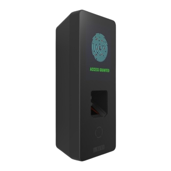
Know Your COSEC ARGO Figure 3: Rear View Figure 1: Front View Touch Screen Display Finger Sensor Card Sensing Area Mounting Screw Hole Back Plate or Wall Mounting Plate Figure 2: Bottom View Flush Mounting Plate Knock Out Area... - Page 3 Pre-Installation Safety Instruction 1. Do not install the device in extremely hot temperature or under direct 5. Do not install the device in outdoor areas which may be exposed Sunlight on turnstile or at extra bright places. This may affect the LCD to rain, cold and dust.
-
Page 4: What Your Package Contains
Preparation for Installation What your Package contains Before Wall mounting and Flush mounting of COSEC ARGO; follow the COSEC ARGO Unit Power Adaptor 12VDC,2A Ÿ Ÿ below steps. Flush Mounting Plate Power Supply Cable (with DC Jack) Ÿ Ÿ 4 Screws M5/25 EM Lock Cable Ÿ... -
Page 5: Technical Specification
Technical Specification COSEC ARGO COSEC ARGO COSEC ARGO COSEC ARGO COSEC ARGO COSEC ARGO Specification Specification FOE212 FOM212 FOI212 FOM212 FOE212 FOI212 User Credential 50,000 Card, Pin and Finger Capacity Support Communication Event Buffer 5,00,000 Ethernet and WiFi Port Input Power 12V DC @2A and PoE Built In WiFi Yes (IEEE 802.11 b/g/n) -
Page 6: Installation Instruction - Wall Mounting
Installation Instruction - Wall Mounting Step 2 Step 1 Drill the screw holes along the traced markings. Place the Wall Mounting plate and trace screw Fix Wall Mounting plate with the supplied screws. holes 1 and 2 on the wall where the device is to Tighten the screws with screw driver. - Page 7 Step 3 Keep all the cables parallel to the side of the COSEC Connect the cables of the ARGO unit and lead all the cables Ÿ ARGO body in such a way that it should not cover the through the duct of the Wall mounting plate into the electrical back of the body as illustrated in below figure.
- Page 8 Step 4 Step 5 Align COSEC ARGO on the mounting plate and hook Insert the mounting screw into the mounting screw into the mounting slot. Press the bottom side inwards hole at the bottom of the device. Tighten the screw to to lock it in place.
-
Page 9: Installation Instruction - Flush Mounting
Installation Instruction - Flush Mounting Step 1 Step 2 Place and fix Flush Mounting plate with the supplied screws. Place the Flush Mounting Template on the desired Ÿ Tighten the screws with screw driver. installation surface. Mark the area along the dotted line and trace the Ÿ... - Page 10 Step 3 Connect the cables of the ARGO unit and lead all the cables Keep all the cables parallel to the side of the COSEC Ÿ through the flush mounting plate into the electrical box ARGO body in such a way that it should not cover the recessed in the wall.
- Page 11 Step 4 Step 5 Align COSEC ARGO on the mounting plate and hook into the Insert the mounting screw into the mounting screw mounting slot. Press the bottom side inwards to lock it in hole at the bottom of the device. Tighten the screw to place.
-
Page 12: Connecting The Cables
Connecting the Cables For Concealed wiring; first draw out sufficient length of the Ÿ cables from the hole you have cut on the mounting surface. Micro USB connector cable Make the electrical connections of Power, External Reader Ÿ EM Lock Cable Ethernet Cable and EM Lock by connecting supplied cable assembly to the 20 pin connector on the back side of COSEC ARGO. - Page 13 Connect the Overswing diode in reverse biased condition Matrix Return Material Authorization (RMA) department. parallel to the EM Lock for a better contact lifetime and to protect the Device from the Inductive kickback.
- Page 14 Copyright All rights reserved. No part of this document may be copied or reproduced in any form or by any means without the prior written consent of Matrix Comsec. Warranty Limited Warranty. Valid only if primary protection is provided, mains supply is within limit and protected, and environment conditions are maintained within product specifications.
Need help?
Do you have a question about the Cosec Argo F0I212 and is the answer not in the manual?
Questions and answers