SICK UM18-2 Pro Operating Instructions Manual
Ultrasonic sensors
Hide thumbs
Also See for UM18-2 Pro:
- Operating instructions manual (40 pages) ,
- Operating instructions manual (54 pages)
Table of Contents
Advertisement
Advertisement
Table of Contents

Related Manuals for SICK UM18-2 Pro


Summary of Contents for SICK UM18-2 Pro
- Page 1 O P E R A T I N G I N S T R U C T I O N S UM18-2 Pro Ultrasonic sensors...
- Page 2 This work is protected by copyright. Any rights derived from the copyright shall be reserved for SICK AG. Reproduction of this document or parts of this document is only permissible within the limits of the legal determination of Copyright Law. Any modification, abridgment or translation of this document is prohibited without the express written permission of SICK AG.
-
Page 3: Table Of Contents
Wiring notes ................19 Connecting the ultrasonic sensor electrically ....... 20 Connection diagrams ............. 21 6.4.1 Ultrasonic sensors with switching outputs .... 21 6.4.2 Ultrasonic sensors with analog outputs ....22 8014865/ZUJ3/2018-11-29 • © SICK AG • Subject to change without notice... - Page 4 SICK-specific UM18-21812A21_ ......37 Error Codes ................38 Cleaning and maintenance ............. 39 Cleaning .................. 39 Maintenance ................39 Troubleshooting ................40 10.1 Possible fault indicators ............40 10.2 Disposal ................... 40 © SICK AG • Subject to change without notice • 8014865/ZUJ3/2018-11-29...
- Page 5 Configuration overview for sensors with switching outputs . 49 13.2 Configuration overview for sensors with analog outputs ..49 13.3 Additional settings for all sensors ......... 50 Index ......................51 8014865/ZUJ3/2018-11-29 • © SICK AG • Subject to change without notice...
- Page 6 © SICK AG • Subject to change without notice • 8014865/ZUJ3/2018-11-29...
-
Page 7: General Information
… indicates a potentially harmful situation, which may lead to material damage if not prevented. Tips and recommendations NOTE! … highlights useful tips and recommendations as well as information for efficient and trouble-free operation. 8014865/ZUJ3/2018-11-29 • © SICK AG • Subject to change without notice... -
Page 8: Limitation Of Liability
Before calling, make a note of all type label data such as type code, serial number etc. to ensure faster processing. EU declaration of conformity → You can download the EU declaration of conformity online from "www.sick.com/um18". © SICK AG • Subject to change without notice • 8014865/ZUJ3/2018-11-29... -
Page 9: Safety
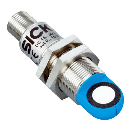
The UM18-2 Pro is an ultrasonic sensor for non-contact detection of objects, animals, and persons. SICK AG assumes no liability for losses or damage arising from the use of the product, either directly or indirectly. This applies in particular to use of the product that does not conform to its intended purpose and is neither described nor mentioned in this documentation. -
Page 10: Requirements For Skilled Persons And Operating Personnel
In Germany, electricians must meet the specifications of the BGV A3 Work Safety Regulations (e.g. Master Electrician). Other relevant regulations applicable in other countries must be observed. © SICK AG • Subject to change without notice • 8014865/ZUJ3/2018-11-29... -
Page 11: Identification
The ultrasonic sensor includes the following type label: POWER D-79183 Waldkirch Made in Germany Fig. 1: UM18-2 Pro type label 1 Order number 2 Type designation 3 Information about output 4 Supply voltage 5 Serial number 8014865/ZUJ3/2018-11-29 • © SICK AG • Subject to change without notice... -
Page 12: Type Code
1x Analog output 4 mA ... 20 mA 1x Analog output DC 0 V … 10 V IO-Link available not available Performance Pro version Alignment Straight Angled Table 1: Type code, UM18-2 Pro ultrasonic sensors © SICK AG • Subject to change without notice • 8014865/ZUJ3/2018-11-29... -
Page 13: Structure And Function
Switching/analog output • LED orange: Switching output active/measured value within analog output scaling • LED off: Switching output inactive/measured value outside analog output scaling Table 2: Status indicators (LEDs) 8014865/ZUJ3/2018-11-29 • © SICK AG • Subject to change without notice... -
Page 14: Function
Structure and function Function The UM18-2 Pro is an ultrasonic sensor for performing non-contact distance measurement or detection of objects, animals, and persons. The circuit variations have the following operation modes: Distance to Object (DtO), Window (Wnd), and Object between Sensor and Background (ObSB). -
Page 15: Mounting
≤ ± 3° ≥ ± 3° Fig. 3: Alignment of the sensor for smooth and rough object surfaces Alignment for smooth object surfaces Alignment for rough object surfaces 8014865/ZUJ3/2018-11-29 • © SICK AG • Subject to change without notice... -
Page 16: Mounting Multiple Ultrasonic Sensors
The detection zone is enlarged to a size which covers all synchronized sensors. A maximum of 20 sensors of type UM18-2 Pro can be connected, and they can also be combined with synchronizable SICK ultrasonic sensors from other product families. -
Page 17: Multiplex Mode
The detection zone is enlarged to a size which covers all connected sensors. A maximum of 20 sensors of type UM18-2 Pro can be connected, and they can also be combined with synchronizable SICK ultrasonic sensors from other product families. - Page 18 = 4 • [(1.1 ms • n) + 0.75 ms • (1 + 2 + … + n)] + overall sum of the response times of all connected sensors n: Number of connected sensors Multiplex mode structure and operat- ing principle PIN 5 Fig. 5: Multiplex mode © SICK AG • Subject to change without notice • 8014865/ZUJ3/2018-11-29...
-
Page 19: Electrical Connection
Incorrect wiring may result in operational faults. For this reason: • Follow the wiring notes precisely. NOTE! We recommend using preassembled cables for the wiring. → For preassembled cables, see Internet "www.sick.com/um18", Accessories. 8014865/ZUJ3/2018-11-29 • © SICK AG • Subject to change without notice... -
Page 20: Connecting The Ultrasonic Sensor Electrically
• Do not lay cables parallel to energy cables. Connecting the ultrasonic sensor electrically 1. Ensure that there is no voltage. 2. Connect the ultrasonic sensor according to the connection diagram. → See Page 21, Chapter 6.4. © SICK AG • Subject to change without notice • 8014865/ZUJ3/2018-11-29... -
Page 21: Connection Diagrams
Supply voltage: 0 V Black Switching output / Q/Q/C IO-Link communication Gray Multifunction input/output for • External teach-in • Synchronization mode/multiplex mode • Connect+ communication Table 4: Description of UM18-21xxxAxxx plug 8014865/ZUJ3/2018-11-29 • © SICK AG • Subject to change without notice... -
Page 22: Ultrasonic Sensors With Analog Outputs
Supply voltage: 0 V Black Not assigned Gray Multifunction input/output for • External teach • Synchronization mode/multiplex mode • Connect+ communication Table 5: Description of UM18-21xxx6xxx and UM18-21xxx7xxx plugs © SICK AG • Subject to change without notice • 8014865/ZUJ3/2018-11-29... -
Page 23: Commissioning
8 %. The orange LED lights up when the switching output is active. + 8 % Fig. 9: Teach-in the switching point – Method B 1 Switching point 8014865/ZUJ3/2018-11-29 • © SICK AG • Subject to change without notice... -
Page 24: Teach-In The Window
Even at changing ambient conditions the object is detected in the range of 0 % ... 85 % of the taught-in distance. 85 % Fig. 11: Teach-in the background 1 Background © SICK AG • Subject to change without notice • 8014865/ZUJ3/2018-11-29... -
Page 25: Configuring As Normally Open Or Normally Closed
LEDs. The original settings are retained. Fig. 12: Teach-in the analog output 1 Scaling limit near the sensor 2 Scaling limit away from the sensor 8014865/ZUJ3/2018-11-29 • © SICK AG • Subject to change without notice... -
Page 26: Configuring The Rising Or Falling Output Characteristic Curve
For synchronization/multiplex mode, the ultrasonic sensors must be interconnected via the "MF" input (pin 5). You can operate a maximum of 20 UM18-2 Pro sensors in synchronization/multiplex mode. © SICK AG • Subject to change without notice • 8014865/ZUJ3/2018-11-29... -
Page 27: Resetting The Settings To The Factory Setting
4. Before switching off the supply voltage, disconnect "M" from "MF" in order to apply the factory setting. All settings have been reset to the factory setting. The ultrasonic sensor is in normal operational mode. 8014865/ZUJ3/2018-11-29 • © SICK AG • Subject to change without notice... -
Page 28: Temperature Compensation
(e.g. in the case of thermally insulated mounting) and a very high level of accuracy is required. Temperature compensation can be switched off via “Connect+ Adapter,” not temperature-compensated: 0.17 %/K © SICK AG • Subject to change without notice • 8014865/ZUJ3/2018-11-29... -
Page 29: Measured Value Filter
Commissioning Measured value filter Filter settings The following filter settings can be selected for the UM18-2 Pro ultrasonic sensors using "Connect+ Adapter": Filter F00 provides an unfiltered output for the measured values. This mode is not permitted, as undesired EMC faults could result. - Page 30 Away from sensor Away from sensor Away from sensor Away from sensor Away from sensor Away from sensor Away from sensor 1000 Away from sensor Table 7: Filter parameters © SICK AG • Subject to change without notice • 8014865/ZUJ3/2018-11-29...
- Page 31 NOTE! Interfering objects must not create multiple reflections. The ultrasonic sensor must not be covered by interfering objects that affect the detection range. 8014865/ZUJ3/2018-11-29 • © SICK AG • Subject to change without notice...
-
Page 32: Io-Link Interface
• UM18-217xxxxxx: 8 ms • UM18-211xxxxxx: 8 ms • UM18-212xxxxxx: 16 ms • UM18-218xxxxxx: 20 ms Speed COM2 (38.4 kBaud) Process data width 16 bits (frame type 2.2) Table 8: Physical layer © SICK AG • Subject to change without notice • 8014865/ZUJ3/2018-11-29... -
Page 33: Process Data
IO-Link interface Process data The process data for the UM18-2 Pro ultrasonic sensors has a data width of 16 bits. Description Value Access Read Data 2 bytes Data type UINT (unsigned integer) Table 9: Process data Bit 15 Bit 14 Bit 13 Bit 12 Bit 11 Bit 10... -
Page 34: Sick-Specific Um18-21712A21
1) Window operation deactivated for values > 3638. 2) Operation with filter setting "F00" is not permitted, as EMC faults may occur in this case. Table 12: SICK-specific service data UM18-21712A21_ © SICK AG • Subject to change without notice • 8014865/ZUJ3/2018-11-29... -
Page 35: Sick-Specific Um18-21712A21
1) Window operation deactivated for values > 5094. 2) Operation with filter setting "F00" is not permitted, as EMC faults may occur in this case. Table 13: SICK-specific service data UM18-21112A21_ 8014865/ZUJ3/2018-11-29 • © SICK AG • Subject to change without notice... -
Page 36: Sick-Specific Um18-21212A21
1) Window operation deactivated for values > 8733. 2) Operation with filter setting "F00" is not permitted, as EMC faults may occur in this case. Table 14: SICK-specific service data UM18-21212A21_ © SICK AG • Subject to change without notice • 8014865/ZUJ3/2018-11-29... -
Page 37: Sick-Specific Um18-21812A21
Chapter 13.1. 1) Window operation at value. 2) Operation with filter setting "F00" is not permitted, as EMC faults may occur in this case. Table 15: SICK-specific service data UM18-21812A21_ 8014865/ZUJ3/2018-11-29 • © SICK AG • Subject to change without notice... -
Page 38: Error Codes
IO-Link interface Error Codes → For error codes, see IO-Link specification V1.1. © SICK AG • Subject to change without notice • 8014865/ZUJ3/2018-11-29... -
Page 39: Cleaning And Maintenance
To be performed by Cleaning interval depends Clean housing. Specialist on ambient conditions and climate Every 6 months Check the screw connections and plug connections. Specialist Table 16: Maintenance schedule 8014865/ZUJ3/2018-11-29 • © SICK AG • Subject to change without notice... -
Page 40: 10 Troubleshooting
Please observe the following when disposing of the removal sensor: • Do not dispose of the device along with household waste. • Dispose of the device according to the applicable regulations in your country. © SICK AG • Subject to change without notice • 8014865/ZUJ3/2018-11-29... -
Page 41: 11 Technical Data
Fig. 13: Structure: top "UM18-2xxxxxxx1 ultrasonic sensor" bottom "UM18-2xxxxxxx2 ultrasonic sensor" 1 Connection 2 Mounting nuts, width across 24 mm 3 Supply voltage active LED status indicator (green) 4 Switching/analog output LED status indicator (orange) 8014865/ZUJ3/2018-11-29 • © SICK AG • Subject to change without notice... -
Page 42: Optics/Performance
1) For sensors with analog output: depending on the application, subsequent smoothing of the analog signal may increase the response time by up to 200 %. Table 18: Performance data © SICK AG • Subject to change without notice • 8014865/ZUJ3/2018-11-29... -
Page 43: Power Supply
Table 21: Inputs 11.5 Outputs 11.5.1 Sensors with switching outputs Sensors with switching outputs UM18-2xxxxAxxx Switching output • Push-pull: PNP/NPN • HIGH: V – (< 3 V), LOW: < 3 V • IO-Link 8014865/ZUJ3/2018-11-29 • © SICK AG • Subject to change without notice... -
Page 44: Sensors With Analog Outputs
UM18-2xxxxx6xx: Voltage output is short-circuit protected Table 23: Outputs – sensors with analog outputs 11.6 Interfaces IO-Link For sensors with switching outputs Connect+ Configuration interface for communication via "Connect+ Adapter" accessories Table 24: Interfaces © SICK AG • Subject to change without notice • 8014865/ZUJ3/2018-11-29... -
Page 45: Ambient Conditions
• Ultrasonic transducer: polyurethane foam, glass epoxy resin Connections Plug M12, 5-pin Display • Green LED: operation • Orange LED: on when switching/analog output is active Table 26: Structural design 8014865/ZUJ3/2018-11-29 • © SICK AG • Subject to change without notice... -
Page 46: "Detection Zone" Diagrams
4 Example object: aligned plate 500 mm x 500 mm 4 Example object: aligned plate 500 mm x 500 mm 5 Example object: round bar with diameter 10 mm 5 Example object: round bar with diameter 10 mm © SICK AG • Subject to change without notice • 8014865/ZUJ3/2018-11-29... - Page 47 4 Example object: aligned plate 500 mm x 500 mm 4 Example object: aligned plate 500 mm x 500 mm 5 Example object: round bar with diameter 10 mm 5 Example object: round bar with diameter 10 mm 8014865/ZUJ3/2018-11-29 • © SICK AG • Subject to change without notice...
-
Page 48: 12 Accessories
For accessories, go to "www.sick.com/UM18", "Accesso- ries". 12.1 "Connect+ Adapter" (CPA) Description "Connect+ Adapter" with associated software Programming tool including adapter, cable, and T-piece for USB (A/B) Order No. 6037782 © SICK AG • Subject to change without notice • 8014865/ZUJ3/2018-11-29... -
Page 49: 13 Configuration Overview
L+ at MF for approx. 1 s Apply L+ at MF for approx. 1 s Orange LED: switches status Wait approx. 10 s Green LED: stops flashing Normal operation mode 8014865/ZUJ3/2018-11-29 • © SICK AG • Subject to change without notice... -
Page 50: Additional Settings For All Sensors
To change the setting, apply M at MF for approx. 1 s Orange LED: changes status Wait approx. 10 s Green LED: stops flashing Normal operation mode © SICK AG • Subject to change without notice • 8014865/ZUJ3/2018-11-29... -
Page 51: Index
Method A ..............23 Method B ..............23 LEDs ................13 Sensors with analog outputs ........25 Limitation of liability ............8 Sensors with switching outputs ......... 23 Two-way reflection barrier .......... 24 8014865/ZUJ3/2018-11-29 • © SICK AG • Subject to change without notice... - Page 52 Teaching in the analog output ........25 Technical data ............... 41 Troubleshooting ............. 40 Type code ............... 12 Type label ............... 11 Window ................24 Wiring notes ..............19 © SICK AG • Subject to change without notice • 8014865/ZUJ3/2018-11-29...
- Page 54 Phone +36 1 371 2680 Phone +386 591 788 49 E-Mail office@sick.hu E-Mail office@sick.si India South Africa Phone +91 22 6119 8900 Phone +27 11 472 3733 Further locations at www.sick.com E-Mail info@sick-india.com E-Mail info@sickautomation.co.za SICK AG | Waldkirch | Germany | www.sick.com...
Need help?
Do you have a question about the UM18-2 Pro and is the answer not in the manual?
Questions and answers