Table of Contents
Advertisement
OPERATION AND SERVICE MANUAL
Model 2925, 2935, 2945
MODEL 2925 (ENHANCED AC ONLY HIPOT WITH GROUND CONTINUITY CHECK)
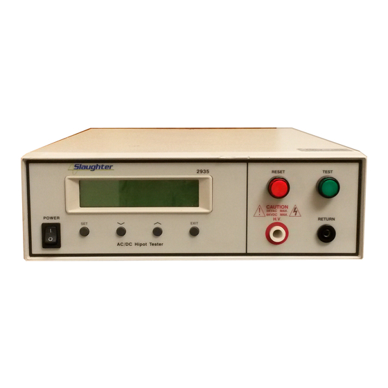
MODEL 2935 (ENHANCED AC/DC HIPOT WITH GROUND CONTINUITY CHECK)
MODEL 2945 (ENHANCED AC/DC HIPOT WITH IR AND GROUND CONTINUITY)
SERIAL NUMBER
Models
© Slaughter Company, Inc., 2004
28105 N. Keith Drive
2925,2935,2945
Lake Forest, Illinois, 60045-4546
U.S.A.
Item 99-10090-01 Ver 1.05
Printed November 11, 2004
Advertisement
Table of Contents

Related Manuals for Slaughter 2925


Summary of Contents for Slaughter 2925
- Page 1 OPERATION AND SERVICE MANUAL Model 2925, 2935, 2945 MODEL 2925 (ENHANCED AC ONLY HIPOT WITH GROUND CONTINUITY CHECK) MODEL 2935 (ENHANCED AC/DC HIPOT WITH GROUND CONTINUITY CHECK) MODEL 2945 (ENHANCED AC/DC HIPOT WITH IR AND GROUND CONTINUITY) SERIAL NUMBER Models ©...
- Page 3 Warranty Policy Slaughter Company, certifies that the instrument listed in this manual meets or exceeds published manufacturing specifications. This instrument was calibrated using standards that are traceable to the National Institute of Standards and Technology (NIST). Your new instrument is warranted to be free from defects in workmanship and material for a period of (1) year from date of shipment.
-
Page 5: Table Of Contents
TABLE OF CONTENTS SECTION I OPERATORS MANUAL ................1 SAFETY ...........................2 INTRODUCTION ......................6 SPECIFICATIONS ......................12 CONTROLS ........................18 INSTALLATION ......................22 QUICK START ......................25 OPERATION ........................28 OPTIONS ........................44 SECTION II SERVICE MANUAL ................47 CALIBRATION ......................48 PARTS LIST ........................51 SCHEMATICS .......................52... -
Page 7: Section I Operators Manual
SECTION 1 OPERATORS MANUAL... -
Page 8: Safety
SAFETY SAFETY PRECAUTIONS REQUIRED FOR HIGH VOLTAGE TESTING! GENERAL: This product and its related documentation must be reviewed for familiarization with safety markings and instructions before operation. This product is a Safety Class I instrument (provided with a protective earth terminal). Before applying power verify that the instrument is set to the correct line voltage (115 or 230) and the correct fuse is installed. - Page 9 The instrument and its power cord, test leads, and accessories must be returned at least once a year to a Slaughter Company authorized service center for calibration and inspection of safety related components. Slaughter Company will not be held liable for injuries suffered if the instrument is not returned for its annual safety check and maintained properly.
- Page 10 SAFETY If benches are placed back-to-back, be especially careful about the use of the bench opposite the test station. Signs should be posted: "DANGER - HIGH VOLTAGE TEST IN PROGRESS - UNAUTHORIZED PERSONNEL KEEP AWAY." Power Dielectric Voltage-Withstand Test Equipment must be connected to a good ground. Be certain that the power wiring to the test bench is properly polarized and that the proper low resistance bonding to ground is in place.
- Page 11 SAFETY Dress Operators should not wear jewelry which could accidentally complete a circuit. Medical Restrictions This instrument should not be operated by personnel with heart ailments or devices such as pacemakers. TEST PROCEDURES !NEVER PERFORM A HIPOT TEST ON ENERGIZED CIRCUITRY OR EQUIPMENT! If the instrument has an external safety-ground connection be sure that this is connected.
-
Page 12: Introduction
INTRODUCTION GLOSSARY OF TERMS (as used in this manual) Alternating Current, AC: Current which reverses direction on a regular basis, commonly in the U.S.A. 60 times per second, in other countries 50 times per second. Breakdown: The failure of insulation to effectively prevent the flow of current, sometimes evident by arcing. - Page 13 INTRODUCTION INTRODUCTION The importance of testing... User safety In an era of soaring liability costs, original manufacturers of electrical and electronic products must make sure every item is as safe as possible. All products must be designed and built to prevent electric shock, even when users abuse the equipment or bypass built in safety features.
- Page 14 INTRODUCTION However, specific products may be tested at much higher voltages than 2X operating voltages + 1,000 volts. For example, a product designed to operate in the range between 100 to 240 volts, can be tested between 1,000 to 4,000 volts or higher. Most "double insulated"...
- Page 15 INTRODUCTION sensitive to a sudden application of voltage the operator can immediately apply full voltage and read current without any wait time. Another advantage of AC testing is that since AC voltage cannot charge a load there is no need to discharge the item under test after the test. AC testing disadvantages A key disadvantage of AC testing surfaces when testing capacitive products.
- Page 16 INTRODUCTION Since a DC hipot does charge the item under test it becomes necessary to discharge the item after the test. DC testing unlike AC testing only charges the insulation in one polarity. This becomes a concern when testing products that will actually be used at AC voltages. This is a key reason that some safety agencies do not accept DC testing as an alternative to AC.
- Page 17 INTRODUCTION measured value represents the equivalent resistance of all the insulation which exists between the two points and any component resistance which might also be connected between the two points. Although the IR test can be a predictor of insulation condition, it does not replace the need to perform a Dielectric Withstand test.
-
Page 18: Specifications
Can be adjusted during operation via UP and DOWN arrow keys. OUTPUT 2925 : 50 / 60 Hz selectable FREQUENCY 2935 and 2945 : DC and 50 / 60 Hz selectable Sinewave, Distortion : 2 THD WAVE FORM ... - Page 19 SPECIFICATIONS Descriptions Specifications METERING Voltmeter (4 digits) Range : AC 0.00 - 5.00 KV : DC 0.00 - 6.00 KV Resolution : .01 KV : (2 of reading 10 V) Accuracy Ammeter (4 digits) Range : AC 0.10 - 12.00 mA : DC 0.02 - 5.00 mA Resolution : 0.01 mA : ...
- Page 20 1. Remote control : test and reset 2. Outputs : pass, fail and test in process PROGRAM MEMORY 5 Sets (2925, 2935, and 2945) SECURITY Key Lock capability to avoid unauthorized access to all test parameters. Memory Lock capability to avoid unauthorized access to memory locations.
- Page 21 SPECIFICATIONS KEY FEATURES & BENEFITS OF MODELS 2925, 2935, and 2945 1. No load setup of trip current and output voltage. This provides the operator with an easy and safe way to set trip currents and output voltages since parameters are set without the high voltage activated.
- Page 22 SPECIFICATIONS 11. Software calibration control. The 2900 family of Hipots is calibrated through the front panel keypad. All calibration information is stored in non-volatile memory. This allows the instrument to be completely calibrated without removing any covers and exposing the technician to hazardous voltages.
- Page 23 SPECIFICATIONS 20. Insulation Resistance Test Mode * This allows the operator to perform an Insulation Resistance test independently or in sequence with the Dielectric Withstand (Hipot) test, thus eliminating the need for a separate piece of test equipment when IR testing is required. 21.
-
Page 24: Controls
CONTROLS FRONT PANEL CONTROLS 1. LCD DISPLAY: The Liquid Crystal Display is the main readout for the operator and programmer of the test settings and test results. 2. RESET SWITCH: This is a momentary contact switch. If an out-of-range reading is detected during a hipot test or an IR test or if continuity failure occurs, the red failure lamp within the switch will light. - Page 25 CONTROLS FRONT PANEL CONTROLS ) 7. UP ARROW ( : Use this key to increment numeric values in the setup mode. This key also used to toggle ON/OFF functions. Also may be used to increase output voltage during a test in 10-volt increments. 8.
- Page 26 CONTROLS REAR PANEL CONTROLS 4 5 6 Cal. 1. THERMAL FAN: To cool the instrument. 2. INPUT POWER SWITCH: Line voltage selection is set by the position of the switch. In the down position, it is set for 115-volt operation, in the up position it is set for 230-volt operation.
- Page 27 CONTROLS REAR PANEL CONTROLS 4 5 6 Cal. 8. CALIBRATION ENABLE KEY: To enter the calibration mode press this key while the instrument is being powered ON.
-
Page 28: Installation
If the shipping carton is damaged, inspect the contents for visible damage such as dents, scratches, or broken meters. If the instrument is damaged, notify the carrier and the Slaughter Company customer support department immediately. Please save the shipping carton and packing material for the carriers inspection. Our customer support department will assist you in the repair or replacement of your instrument. - Page 29 INSTALLATION Power Cable BEFORE CONNECTING POWER TO THIS INSTRUMENT, THE WARNING PROTECTIVE GROUND (EARTH) TERMINALS OF THIS INSTRUMENT MUST BE CONNECTED TO THE PROTECTIVE CONDUCTOR OF THE LINE (MAINS) POWER CORD. THE MAIN PLUG SHALL ONLY BE INSERTED IN A SOCKET OUTLET (RECEPTACLE) PROVIDED WITH A PROTECTIVE GROUND (EARTH) CONTACT.
- Page 30 4). Seal the container securely. 5). Mark the container "FRAGILE" to insure proper handling. 6). Please ship models 2925, 2935, and 2945 via Federal Express or UPS air. 7). Please refer in all correspondence to your RMA number. Field Installation Of Options...
-
Page 31: Quick Start
"default" settings on the instrument. The default settings shown will remain in memory unless you choose to override them with your own test program. The default settings will appear in memories 1 through 5 for models 2925, 2935, and 2945. The instrument default settings are as follows: DEFAULTS ... - Page 32 All of the front panel led's will light temporarily then go out. In addition, you will see the Slaughter Company name and Model Number briefly appear on the LCD readout and then clear itself.
- Page 33 QUICK START These abbreviated parameters stand for the following: SET: This is the parameter settings review screen. W - SET: This is the parameter settings review screen for Dielectric Withstand test mode. Indicates the memory location of the current settings. M1_: Indicates that an Insulation Resistance test will execute after the Dielectric Withstand test is completed successfully.
-
Page 34: Operation
The instrument is now ready for operation. B. SETUP PROCEDURE: 1. To select the Memory location on models 2925, 2935, and 2945 Please press the SET key until the display shows M e m o r y Use the Up/Down arrow keys to select memory locations 1 through 5. - Page 35 EXIT key to exit to the test mode or toggle to another setting using the SET key. 4. To set the Output Test Voltage Please press the SET key until the display shows: Models 2925, 2935 Model 2945 V o l t a g e = X.XX...
- Page 36 0.10 AC and 0.02 DC milliamperes as the minimum setting. 6. To set the Low Leakage Current Limit on models 2925, 2935, and 2945 Please press the SET key until the display shows:...
- Page 37 9. To setup the Ground Continuity Check Please press the SET key until the display shows Models 2925 and 2935 C o n t i n u i t y C o n t i n u i t y = O FF...
- Page 38 OPERATION conjunction with the Key Lock. Within this selection, you can lockout all front panel control functions except TEST, RESET and memory select. You can toggle this selection only from a power OFF state. Please turn the POWER switch to the off position then press and hold the SET key, then turn the power ON. Momentarily you will see one of the following screens to indicate if the keys are locked or unlocked: Key Lock = ON...
- Page 39 OPERATION I - H i g h XXXX M Use the Up/Down Arrow keys to enter the resistance high limit setting, then press the EXIT key to exit to the test mode or toggle to another setting using the SET key. The unit of measure is in megohms with 0 - 1000 range of setting.
- Page 40 2. Please follow the setup procedures to set the parameters. The display will show the Dwell or Delay Timer value, the Test Voltage value, and the High Limit Setting. On model 2925, 2935, and 2945 the memory location will also be displayed.
- Page 41 X . XX K V A C XX . XX mA The instrument will continue to output the desired voltage for the duration of the selected dwell time for model or selected Ramp and Dwell times on model 2925, 2935, and 2945.
- Page 42 5. If there is a short circuit in the DUT during the test, the red indicator light will illuminate on the RESET switch and an alarm will sound. The display will show: models 2925 and 2935 H I - F A I L XXX .
- Page 43 X . XX K V A C XX.XX mA 9. If the leakage current does not exceed the low limit setting on model 2925, 2935, and 2945, the red indicator light will illuminate on the RESET switch and an alarm will sound.
- Page 44 12. If the operator elects to abort a test in process this can be accomplished by pressing the RESET switch at anytime. The instrument will stop the test process immediately and the display will show: models 2925 and 2935 A b o r t XXX . X s X .
- Page 45 OPERATION 16. If the insulation resistance exceeds the high limit setting, but does not exceed the metering range, the red indicator light will illuminate on the RESET switch and an alarm will sound. The display will show: I - H i g h XXX .
- Page 46 OPERATION D. CONNECTION OF REMOTE I/O: A 9-pin “D” type connector is mounted on the rear panel which provides REMOTE- INPUT-OUTPUT control and information. This connector mates with standard 9-pin “D” subminiature connector provided by the user. The Remote I/O mates to a female (receptacle) connector.
- Page 47 OPERATION The following describes how the relays operate for each test condition. PROCESSING - The relay contact closes the connection between pin (1) and pin (4) while the instrument is performing a test. The connection is opened at the end of the test. PASS - The relay contact closes the connection between pin (6) and pin (7) after detecting that the item under test passed all tests.
- Page 48 When the 2925, 2935, or 2945 tests the ground conductor of the line cord, if the resistance of the ground conductor exceeds 1, the hipot will signal a continuity failure.
- Page 49 OPERATION...
-
Page 50: Options
OPTIONS MODEL 2925, 2935, and 2945 OPTIONS Introduction This section contains a list and descriptions of available factory installed options at the time of this printing. The list of options contains an option code number which can be referenced on the model option label on the rear panel of the unit when options are present. - Page 51 OPTIONS OPTIONAL REAR PANEL CONTROLS Description 01 Rear Outputs The Rear Outputs option gives the user the capability to access the High Voltage and Return in addition to the existing Continuity output from the rear panel for use in automated systems. The configuration and descriptions are as follows. 1.
- Page 52 OPTIONS closed (must open contacts to activate the reset). Hardware and software have been reconfigured to provide the interlock connections on pins 2 and 5 of the Remote Interface Signal Input port. This reset scheme is designed for use with an external safety interlock device that utilizes a "Fail-When-Open"...
-
Page 53: Section Ii Service Manual
SECTION 2 SERVICE MANUAL... -
Page 54: Calibration
"Certificate of Calibration". It is recommended that you have this instrument recalibrated and a safety check done at least once per year. Slaughter recommends you use "Calibration Standards" that are NIST traceable, or traceable to agencies recognized by NIST to keep this instrument within published specifications. - Page 55 CALIBRATION 1. Calibration of Voltage Equipment needed: STANDARD AC VOLTMETER capable of measuring 5000VAC. Please connect a standard ac voltmeter with 5000V minimum full scale range to the high voltage and return connectors. Then press the SET key on the front panel. The instrument will provide around 5000VAC on the output connectors and the display will show: V o l t a g e = __ Please use the Up/Down Arrow keys to enter the reading off the AC Voltmeter into the...
- Page 56 CALIBRATION 3. Calibration of Insulation Resistance Current model 2945 Equipment needed: STANDARD DC MILLIAMMETER with a range of 2000uA and a fixed Resistor 500K Ohm, 50 watts. Please connect a 500K resistor in series with the standard DC microammeter and connect these across the output leads of the instrument.
-
Page 57: Parts List
Model 2925, 2935, and 2945 Rev. C ECO 5040-6 Part Number Qty. Reference Description Designator 99-10010-01 CGC-03 Ground Continuity Board (2925 and 2935) 99-10011-01 CGC-03 Ground Continuity Board (2945) 99-10012-01 CHV-04 High Voltage Control Board (2935, 2945) 99-10222-01 CKB-06 Key Board Assembly... -
Page 58: Schematics
PARTS LIST SCHEMATIC INDEX Drawing Number Description Pages S02900 Wiring Diagram S99-10015 Main Control Board S99-10010 Ground Continuity Check Board S99-10011 Ground Continuity Check Board w/IR test S99-10012 HV Control Board AC/DC S99-10222 Keypad Board S99-10014 Input Protection Board S99-10036 ROM Conversion Board...
Need help?
Do you have a question about the 2925 and is the answer not in the manual?
Questions and answers