
Related Manuals for Slaughter 4320


Summary of Contents for Slaughter 4320
- Page 1 Model 4320, 4520 V2.00 MODEL 4320 (AC/DC HIPOT WITH IR AND GROUND BOND TESTERS) MODEL 4520 (500VA AC/DC HIPOT WITH IR AND GROUND BOND TESTERS) Item 99-10319-01 Printed October 30th, 2014...
-
Page 2: Declaration Of Conformity
DECLARATION OF CONFORMITY Manufacturer: Slaughter Company, Inc. Address: 28105 N. Keith Drive Lake Forest, IL 60045 Product Name: 4320 Electrical Safety Compliance Analyzer Model Number: 4320 Conforms to the following Standards: Safety: UL 61010-1:2012 CAN/CSA-C22.2 NO. 61010-1-12 EN 61010-1:2010, EN 61010-2-030:2010, EN 61010-031:2002+A1... - Page 3 DECLARATION OF CONFORMITY Manufacturer: Slaughter Company, Inc. Address: 28105 N. Keith Drive Lake Forest, IL 60045 Product Name: 4520 Electrical Safety Compliance Analyzer Model Number: 4520 Conforms to the following Standards: Safety: EN 61010-1:2010 EN 61010-2-030:2010, EN 61010-031:2002+A1 EMC: EN 61326:2006 Class A,...
-
Page 4: Warranty Policy
The return method will be at the discretion of Slaughter Company. Except as provided herein, Slaughter Company makes no warranties to the purchaser of this tester and all other warranties, express or implied (including, without limitation, merchantability or fitness for a particular purpose) are hereby excluded, disclaimed and waived. -
Page 5: Table Of Contents
TABLE OF CONTENTS SAFETY PRECAUTIONS REQUIRED FOR HIGH VOLTAGE TESTING! ........1 FRONT PANEL CONTROLS....................2 4320 REAR PANEL CONTROLS .....................4 4520 REAR PANEL CONTROLS .....................5 SETUP INSTRUCTIONS FOR MODEL 4320/4520 ..............6 POWER-UP SEQUENCE: .......................6 : ....................8 ETTING TO ESTER ..................8 ORKING WITH EMORIES ....................8... - Page 6 APPENDIX D - REMOTE BUS INTERFACE: RS-232 .............41 APPENDIX E - REPLACEMENT PARTS LIST - MODEL 4320/4520 ........50 APPENDIX F - SERVICE AND MAINTENANCE ..............52 APPENDIX G – CALIBRATION PROCEDURE ...............53...
-
Page 7: Safety Precautions Required For High Voltage Testing
SAFETY PRECAUTIONS REQUIRED FOR HIGH VOLTAGE TESTING! GENERAL: This product and its related documentation must be reviewed for familiarization with safety markings and instructions before operation. This product is a Safety Class I tester (provided with a protective earth terminal). Before applying power verify that the tester is set to the correct line voltage (115 or 230) and the correct fuse is installed. -
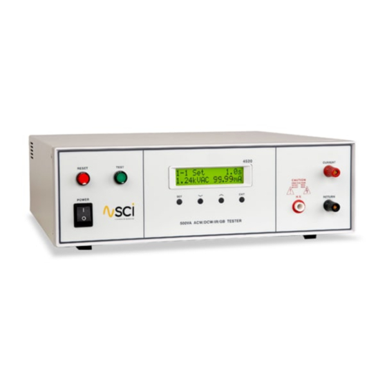
Page 8: Front Panel Controls
Front Panel Controls RESET BUTTON: This is a momentary contact switch used to reset the tester. If an out-of-range reading is detected during a test, the red failure lamp within the button will light. To reset the system for the next test, press and release this button. - Page 9 Front Panel Controls EXIT KEY: Use this key to enter the test mode screen to initiate a test. Also use this key to enter the System menu parameters and to exit from the System menu. HIGH VOLTAGE OUTPUT JACK: For the connection of the detachable 6-foot (1.8 m) red high voltage test lead.
-
Page 10: 4320 Rear Panel Controls
4320 Rear Panel Controls 1. POSITION FOR OPTIONAL REMOTE OUTPUT JACKS: Please refer section Optional Rear Panel Controls for details. 2. FUSE RECEPTACLE: To change the fuse unplug the power (mains) cord and turn the fuse cap counter clockwise to remove the fuse. -
Page 11: 4520 Rear Panel Controls
4520 Rear Panel Controls 1. POSITION FOR OPTIONAL REMOTE OUTPUT JACKS: Please refer section Optional Rear Panel Controls for details. 2. CALIBRATION ENABLE KEY: To enter the calibration mode press this key while the tester is being powered 3. REMOTE INPUT: 9 pin D subminiature male connector for remote control of test, reset, and interlock functions as well as remote memory tests selection. -
Page 12: Setup Instructions For Model 4320/4520
Setup Instructions for Model 4320/4520 Power-Up Sequence: 1. Check to be sure the correct input line voltage has been selected on the rear panel, either 115 volts AC or 230 volts AC. NOTE: The 4520 has an automatic input range selection. - Page 13 5. Turn on the POWER switch located on the lower left hand side of the front panel. Upon powering the tester up, a POWER ON SELF TEST (POST) will automatically be performed. This test will check for the condition of the ram chips, PCB’s and other critical components. In addition the display will show the following message, with the actual model number and software version number.
-
Page 14: Getting To Know Your Tester
Getting to Know Your Tester: 1. Working with Memories The model 4320/4520 is equipped with 6 memory programs numbered 1 through 6. Each memory location contains 6 separate steps that can be connected sequentially to the next consecutive step. Each step contains 4 separate locations, one for each function. Only one function can be selected for each step, but the other three function parameters remain stored in the memory. - Page 15 Follow the setup procedures to set the desired parameters. The display will show the either the Hipot test settings, the Insulation Resistance test settings or Ground Bond test settings depending on what has been selected: Display* Description AC Hipot test display DC Hipot test display Insulation Resistance test display Ground Bond test display...
-
Page 16: Selecting Memory And Step Locations
3. Selecting Memory and Step Locations... -
Page 17: Setting An Ac Hipot Test
4. Setting an AC Hipot Test... -
Page 18: Setting Adc Hipot Test
5. Setting a DC Hipot Test... -
Page 19: Setting An Ir Test
6. Setting an IR Test... -
Page 20: Setting Agnd Bond Test
7. Setting a GND Bond Test... -
Page 21: System Parameter Descriptions
System Parameter Descriptions System Parameter Setting Description Allows the user to initiate a test through the REMOTE INPUT on the rear panel of the tester. If PLC Remote = ON the front panel TEST button is disabled and a test PLC Remote ON/OFF may only be started through the rear panel I/O. -
Page 22: Setting System Parameters
Setting System Parameters... -
Page 23: Using The Display
Using the Display Test Mode Displays Test Mode Display Test Type Description Displayed when the test voltage is ramping up from 0.0 VAC/VDC to full test voltage. AC/DC Hipot Displayed when the test voltage or test current has AC/DC Hipot, reached full potential. -
Page 24: Failure Mode Displays
Displayed if there is a short circuit in the DUT during the test. AC Hipot 4320 only. Displayed if a flash over occurs in the DUT during the test, which results in an OFL condition due to the current AC Hipot exceeds the maximum metering range. - Page 25 4320 only. Displayed if the leakage current exceeds the metering range and neither a short circuit nor flash over DC Hipot occurred. 4520 only. Displayed if the leakage current exceeds the metering range and neither a short circuit nor flash over DC Hipot occurred.
-
Page 26: Error Messages
The failure light and Alarm can be cleared by pressing the RESET button. If Output Error occurs please call the Slaughter Company Customer Support Center at 1- 800-504-0055 for assistance. All of the buttons and keys are not active in this situation. -
Page 27: Using The Remote I/O
Using the Remote I/O: Two 9-pin “D” type connectors are mounted on the rear panel that provides REMOTE-INPUT-OUTPUT control and information. These connectors mate with standard 9 pin D-sub-miniature connector provided by the user. The output mates to a male (plug) connector while the input mates to a female (receptacle) connector. ... -
Page 28: Signals On Remote I/O
Signals on Remote I/O REMOTE INPUT/OUTPUT Remote Output Pins Description Output Signal The relay contact closes after detecting that the device under test passed all tests. The 1 and 2 PASS connection is opened when the next test is initiated or the reset function is activated. The relay contact closes after detecting that the device under test failed any test. - Page 29 Remote Memory Bit Selection Memory # BIT 3 BIT 2 BIT 1 Where: 1 = Momentary Contact closure between BIT and COMMON 0 = NO Contact closure between BIT and COMMON The memory select bits need to be set simultaneously and remain set for a minimum of 20ms to guarantee that the correct memory will be selected.
-
Page 30: Using The Tester Accessories
Using the Tester Accessories: NEVER CONNECT THE ADAPTER BOX OR TEST LEADS TO THE TESTER WHILE THE WARNING HIGH VOLTAGE OUTPUTS ARE ENERGIZED. Using the Test Leads Connect the black return lead (99-10008-01) to the front panel return output terminal and connect the other end of the lead to the dead metal on the chassis of the DUT. -
Page 31: Using The Adapter Box
The adapter box is an optional accessory and is not provided as standard equipment with the model 4320/4520. If you would like to acquire an adapter box for use with your tester, please contact The Slaughter Company using the contact information provided in the Safety section of this manual. -
Page 32: Appendix A - Installation And Test Operator Information
If the shipping carton is damaged, inspect the contents for visible damage such as dents, scratches, or broken meters. If the tester is damaged, notify the carrier and the Slaughter Company customer support department immediately. Please save the shipping carton and packing material for the carrier’s inspection. Our customer support department will assist you in the repair or replacement of your tester. -
Page 33: Contents Of The Carton
(model 4320 only). This may cause internal damage and represents a safety risk to the operator. NOTE For operation at 115 Volts AC and 230 Volts AC use a 6.3 A slow blow fuse (model 4320). For operation at 115 Volts AC and 230 Volts AC use a 15 A slow blow fuse (model 4520). -
Page 34: Power Cable
5. Power Cable BEFORE CONNECTING POWER TO THIS TESTER, THE PROTECTIVE GROUND (EARTH) WARNING TERMINALS OF THIS TESTER MUST BE CONNECTED TO THE PROTECTIVE CONDUCTOR OF THE LINE (MAINS) POWER CORD. THE MAIN PLUG SHALL ONLY BE INSERTED IN A SOCKET OUTLET (RECEPTACLE) PROVIDED WITH A PROTECTIVE GROUND (EARTH) CONTACT. -
Page 35: Packaging
Protect the control panel with cardboard. 5. Seal the container securely. 6. Mark the container "FRAGILE" to insure proper handling. 7. Please ship models 4320/4520 via Federal Express or UPS air. 8. Please refer in all correspondence to your RMA number. -
Page 36: Test Operator And Safety Considerations
Test Operator and Safety Considerations 1. Qualifications This tester generates voltages and currents which can cause harmful or fatal electric shock and must only be operated by a skilled worker trained in its use. The operator should understand the electrical fundamentals of voltage, current, and resistance. 2. -
Page 37: Test Station
Hot stick probes can be used to discharge any capacitance in the item under test as a further safety precaution. A hot stick is a non-conducting rod about two feet long with a metal probe at the end which is connected to a wire. - Page 38 If the tester is used in a matter not specified by Slaughter Company, Inc. the protection provided by the tester may be impaired.
-
Page 39: Appendix B - 4000 Series Tester Specifications
Appendix B - 4000 Series Tester Specifications Model 4320 Functional Specifications Unless otherwise stated, accuracy's are relative to a laboratory standard measurement. INPUT 115 / 230V selectable, 10 variation Voltage 50 / 60 Hz 5% Frequency Fuse 6.3 A slow blow 250V AC... - Page 40 Ramp Timer Range: 0.1 – 999.9 sec Resolution: 0.1 sec (0.1 + 0.05 sec) Accuracy: INSULATION RESISTANCE TEST MODE Output Voltage Range: 100 – 1000 V DC Resolution: (2 of reading + 5 V) Accuracy: Voltage Display Range: 0 –...
- Page 41 Why use the term “Counts”? Slaughter publishes some specifications using COUNTS which allows us to provide a better indication of the tester’s capabilities across measurement ranges. A COUNT refers to the lowest resolution of the display for a...
- Page 42 Model 4520 Functional Specifications Unless otherwise stated, accuracy's are relative to a laboratory standard measurement. INPUT 115 / 230V Auto Range, 15 variation Voltage 50 / 60 Hz 5% Frequency Fuse 15 A slow blow 250V AC HIPOT TEST MODE Output Rating 5 kV @ 100 mA AC...
- Page 43 Ramp Timer Range: 0.1 – 999.9 sec Resolution: 0.1 sec (0.1 + 0.05 sec) Accuracy: INSULATION RESISTANCE TEST MODE Output Voltage Range: 100 – 1000 V DC Resolution: (2 of reading + 2 counts) Accuracy: Voltage Display Range: 0 –...
- Page 44 Why use the term “Counts”? Slaughter publishes some specifications using COUNTS which allows us to provide a better indication of the tester’s capabilities across measurement ranges. A COUNT refers to the lowest resolution of the display for a...
-
Page 45: Appendix C - 4320/4520 Options
Appendix C - 4320/4520 Options Introduction This section contains a list and descriptions of available factory installed options at the time of this printing. The list of options contains an option code number which can be referenced on the model option label on the rear panel of the unit when options are present. - Page 46 This option may be added as a serial type communication protocol. This option provides all of the function control of the RS-232 interface. The 9-pin D-type subminiature connector labeled “RS-232” is for connection of the 4320/4520 to any compatible PC. When selecting RS232, the protocol for interfacing and communicating with a PC can be found on Annex D: Remote Bus Interface: RS232 of this manual.
-
Page 47: Appendix D - Remote Bus Interface: Rs-232
APPENDIX D - Remote BUS Interface: RS-232 This section provides information on the proper use and configuration of bus remote interface. The RS-232 remote interface is optional on all 4320/4520 models. Please see the OPTIONS section of the manual for details. - Page 48 The following conventions are used to describe the commands syntax for the 4320/4520. Braces ({ }) enclose each parameter for a command string. Triangle brackets (< >) indicate that you must substitute a value for the enclosed parameter. The Pipe ( | ) is used to separate different parameter options for a command. The command and the parameter data must be separated with a space.
- Page 49 File Editing Commands and Companion Queries The following commands are used to create or modify Test Setup Files. COMMAND DESCRIPTION VALUE FL <file number> File Load file number = 1-6 SS <step number> Step Select step number = 1-6 Step Add ACW test Step Add DCW test Step Add IR test Step Add GND test...
- Page 50 0.0, 0.5 – 999.9s 0.0 = Continuous EF {1|0} Edit Frequency 1=60Hz, 0=50Hz EH < value > Edit HI-Limit 4320: 0.0 – 20,000uA 4520: 0.0 – 99,990uA 4320: 0.0 – 5,000uA 4520: 0.0 – 10,000uA 0 - 1000M 0 - 510m...
- Page 51 COMMAND NAME TEST TYPES VALUE EL < value > Edit LO-Limit 0.0 – 20,000uA 0.0 – 5,000uA 0 - 1000M 0 - 510m EO < value > Edit Offset 0 - 100mΩ ERU < value> Edit Ramp-Up 0.1 - 999.9s ERU? EV <value>...
- Page 52 Query Commands These query commands will retrieve data from the tester. These commands include functions for retrieving test data, test results and remote hardware. COMMAND NAME VALUE List Testing Data Data from test in Process RD <step number>? Result Data Query Read Reset Query 1=Open, 0=Closed Read Interlock...
- Page 53 *ESR?, *ESE, *ESE? and *STB?. COMMAND NAME DESCRIPTION *IDN? Identification Query SLA, Model Number, Serial Number, Firmware Revision *RST Reset Command Resets 4320/4520 *TST? Self-Test Query 00H=OK 01H=TEST EEPROM ERROR *CLS Clear Status Command Clear Standard Event Status Register Clear Service Request Register *OPC...
- Page 54 *IDN? Read the tester identification string. Company =SLA. *RST Reset the tester to original power on configuration. Does not clear Enable register for Standard Summary Status or Standard Event Registers. Does not clear the output queue. Does not clear the power-on-status- clear flag.
- Page 55 *STB? Read the Status Byte. Returns the decimal value of the binary-weighted sum of bits. *SRE <value> Service Request enable register controls which bits from the Status Byte should be use to generate a service request when the bit value = 1. *SRE? Queries the Service Request enable register.
-
Page 56: Appendix E - Replacement Parts List - Model 4320/4520
Appendix E - Replacement Parts List - Model 4320/4520 Rev: D PART QTY. REFERENCE DESCRIPTION NUMBER DESIGNATOR 99-10320-01 CON4320 Main Control Board 4320 99-10639-01¹ CON4320 Main Control Board 4520 99-10321-01 AMP4320 Amplifier Board 4320 99-10637-01¹ AMP3780 Amplifier Board 4520 99-10322-01... - Page 57 99-10303-01 Microcontroller 8 Bit W78E516B 99-10304-01 IC24 Microcontroller 8 Bit SM8951A 99-10030-01 IC50 12 Bit D/A Converter 7541 99-10032-01 IC20 8 Bit D/A Converter DAC 0800 99-10671-01 Test/Pass Replacement Bulb 99-10672-01 Reset/Fail Replacement Bulb ¹ 4520 Only ² 4320 Only...
-
Page 58: Appendix F - Service And Maintenance
Service Interval The tester and its power cord, test leads, and accessories must be returned at least once a year to a Slaughter Company authorized service center for calibration and inspection of safety related components. Slaughter Company will not be held liable for injuries suffered if the tester is not returned for its annual safety check and maintained properly. -
Page 59: Appendix G - Calibration Procedure
Calibration". It is recommended that you have this tester recalibrated and a safety check done at least once per year. Slaughter recommends you use "Calibration Standards" that are NIST traceable, or traceable to agencies recognized by NIST to keep this tester within published specifications. - Page 60 To calibrate AC voltage please follow procedure on next paragraph, to calibrate other parameters use Up () or Down () arrow keys to scroll to the desired calibration point, then follow procedure on relative paragraph below. When the calibration process is completed successfully and the tester accepts the entered calibration data it will output one short “beep”...
- Page 61 Press the Up () or Down () arrow keys to enter the reading of the standard DC Voltmeter into the tester. Then press SET key to store the voltage setting and to advance to the next calibration point or press the RESET button to return to the calibration menu without changing the calibration setting.
- Page 62 Press the Up () or Down () arrow keys to enter the reading of the standard AC Milliammeter into the tester. Then press SET key to store the current setting and to advance to the next calibration point or press the RESET button to return to the calibration menu without changing the calibration setting.
- Page 63 7. To calibrate Insulation Resistance range Please connect a 100k standard resistor across the HV and RETURN connectors. Press the Up () or Down () arrow keys until the display shows: Then press the TEST button on the front panel. The tester will execute automatic calibration process. The process does not require data entry.
- Page 64 The tester will output one short “beep” and advance to the next calibration point when the automatic process is completed successfully, otherwise the tester will output two short “beeps” and will not advance to the next calibration point. When previous calibration point was completed successfully display will show: Please connect a 50M...
- Page 65 The tester will output one short “beep” and advance to the next calibration point when the automatic process is completed successfully, otherwise the tester will output two short “beeps” and will not advance to the next calibration point. 8. To calibrate Ground Bond test voltage Please connect a standard 6V AC Voltmeter across the CURRENT and RETURN connectors of the tester.
- Page 66 Press the Up () or Down () arrow keys to enter the reading of the standard AC Ammeter into the tester. Then press SET key to store the current setting and to advance to the next calibration point or press the RESET button to return to the calibration menu without changing the calibration setting.
Need help?
Do you have a question about the 4320 and is the answer not in the manual?
Questions and answers