Table of Contents
Advertisement
SAFETY CHECKLIST
KEEP unqualified/unauthorized personnel away from the test area
ARRANGE test stations in a safe and orderly manner
NEVER touch products or connections during a test
STOP the test first in the event of a problem
NEVER perform a Ground Bond test on energized circuitry or equipment
BE SURE to always connect the return test lead first
HANDLE test clips by insulation only, never touch clips directly
WARNING:
ELECTRICAL SAFETY TESTING. AN ELECTRICAL SAFETY TESTER PRODUCES VOLTAGES AND CURRENTS THAT
CAN CAUSE HARMFUL OR FATAL ELECTRIC SHOCK. TO PREVENT ACCIDENTAL INJURY OR DEATH, THESE
SAFETY PROCEDURES MUST BE STRICTLY OBSERVED WHEN HANDLING AND USING A TEST INSTRUMENT.
Safety Made Simple
THIS GUIDE WAS CREATED FOR OPERATORS HAVING SOME FAMILIARITY WITH
2900 Series
Quick Start Guide
For Models: 2955, 2965 & 2975
Advertisement
Table of Contents

Subscribe to Our Youtube Channel
Related Manuals for Slaughter 2900 Series


Summary of Contents for Slaughter 2900 Series
-
Page 1: Quick Start Guide
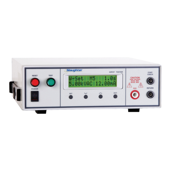
Safety Made Simple 2900 Series Quick Start Guide SAFETY CHECKLIST KEEP unqualified/unauthorized personnel away from the test area ARRANGE test stations in a safe and orderly manner NEVER touch products or connections during a test STOP the test first in the event of a problem... - Page 2 Front Panel Controls 2955/2965/2975 10 11 (2955 Front Panel) RESET BUTTON: Red momentary contact switch used to reset the instrument in case of a failure. Also serves as an abort signal to stop any test in progress. TEST BUTTON: Starts a test. LCD DISPLAY: 16 x 2 character display.
- Page 3 Back Panel Controls 2955/2965/2975 (2955 Back Panel) CALIBRATION KEY: Press this key while the instrument is being powered on to enter calibration mode. REMOTE INPUT/OUTPUT: 9-pin D subminiature male connector for remote control of TEST and RESET functions as well as for monitoring PASS, FAIL, and PROCESSING output relay signals.
- Page 4 4. Turn the instrument power switch ON. HIPOT TESTER RESET TEST POWER EXIT Upon power up, you will see the Slaughter company name, model number, and the current software version briefly appear on the display and then you will see the default test parameters as shown.
- Page 5 Editing Test Parameters If you wish to change the default test settings, you will need to begin by choosing a memory location first. 1. Press the SET key from the Perform Test screen to select a memory location. Use the up or down arrow keys to select memory locations 1 –...
- Page 6 Test Connections DUT Connection Connect the black return lead (102-069-904) to the front panel return output terminal and connect the other end of the lead to the dead metal on the chassis of the DUT. Connect a second black return lead (102-069-904) to the front panel continuity check terminal and connect the other end of the lead to the third prong on the line cord coming from the DUT .
- Page 7 Test Connections Adapter Box Connection The adapter box (99-10001-01) is available as an option accessory for the 2900 series. It provides an easy way to connect to a DUT that is terminated in a two-prong or three-prong line cord. Connect the black return lead (102-069-904) to the front panel return output terminal and connect the other end of the lead to the dead metal on the chassis of the DUT.
- Page 8 To stop the alarm press the red RESET button. Scan the QR code to get further support or visit www.hipot.com/ 29xx_Support/ Safety Made Simple www.hipot.com Toll Free +1-800-504-0055 or +1-847-932-3662 © 2013 Slaughter Company, Inc. 29XX 6/14...
Need help?
Do you have a question about the 2900 Series and is the answer not in the manual?
Questions and answers