Table of Contents
Advertisement
Advertisement
Table of Contents

Subscribe to Our Youtube Channel
Related Manuals for Slaughter 2205


Summary of Contents for Slaughter 2205
- Page 1 OPERATION AND SERVICE MANUAL Model 2205 0 – 1.0KV DC / 0.1MΩ – 200GΩ INSULATION RESISTANCE TESTER SERIAL NUMBER © Slaughter Company, Inc., 2002 Model 2205 28105 N. Keith Drive Lake Forest, Illinois, 60045-4546 U.S.A. Item 99-10268-01 Ver 1.04 Printed April 29, 2013...
-
Page 3: Warranty Policy
Warranty Policy Slaughter Company, certifies that the instrument listed in this manual meets or exceeds published manufacturing specifications. This instrument was calibrated using standards that are traceable to the National Institute of Standards and Technology (NIST). Your new instrument is warranted to be free from defects in workmanship and material for a period of (1) year from date of shipment. -
Page 5: Table Of Contents
TABLE OF CONTENTS INTRODUCTION ________________________________________________________2 INSTALLATION AND SAFETY___________________________________________________ 2 SERVICE AND MAINTENANCE __________________________________________________ 10 GLOSSARY OF TERMS _________________________________________________________ 12 SPECIFICATIONS _______________________________________________________14 CONTROLS ____________________________________________________________17 QUICK START __________________________________________________________21 SETUP _________________________________________________________________23 OPERATION ___________________________________________________________26 REMOTE I/O ___________________________________________________________29 CALIBRATION _________________________________________________________31 REPLACEMENT PARTS LIST ____________________________________________32 SCHEMATIC INDEX ____________________________________________________33... -
Page 6: Introduction
INTRODUCTION INTRODUCTION This section is prepared to assist the user of Slaughter manually operated bench type test equipment with the use, installation, inspection and maintenance of the equipment. Since any electrical equipment can be hazardous, all procedures described should be... - Page 7 INTRODUCTION To check the unit quickly, install any interface connectors, plug the unit into the proper voltage and follow the steps outlined under operating instructions. If the unit does not operate, contact the factory for instructions. Of prime consideration and importance in the layout and installation of a test station is to insure the safety both to the operator and any visitors or casual bystanders, invited or otherwise.
- Page 8 INTRODUCTION the case of a grounded part the conductive table or conveyor should not be touched during a test. Several models of high voltage test equipment are designed with the high voltage output "floating". There is no ground on either the High side or the Low side of the high voltage transformer.
- Page 9 INTRODUCTION bear in mind it is possible for some sections of the skin to have poor electrical connection and that they thereby, can become a potential safety hazard in the event of a fault. This is why isolation of the vehicle during the test is recommended. Once these safety precautions have been taken and it has been established that the frame and skin are properly grounded, the operator can proceed with the dielectric test.
- Page 10 INTRODUCTION Secondly, hipot testing is done as a quality control measure. Incipient failures in the insulation of any portion of the product, whether due to workmanship, components or materials are detected by the hipot test before the product is shipped out to cause inconvenience, dissatisfaction and expense in the field.
- Page 11 INTRODUCTION A hipot test attempts to detect or measure phenomena that indicate electrical problems such as leakage, breakdown and arcing. Leakage is a flow of current. Leakage becomes significant under two conditions. Any increase in resistive leakage is a "red flag" indication that quality in insulating materials used in the device has in some manner deteriorated.
- Page 12 INTRODUCTION The capacitive leakage is an inherent characteristic of the device controlled primarily by design details. The resistive leakage is a characteristic of insulating materials used and the amount of resistive leakage is generally an indication of the quality of the insulation. This is particularly true when identical devices are being comparatively tested.
- Page 13 INTRODUCTION The ability of high voltage test equipment to react to the excessive current flow or failure of the product under test is often referred to as "sensitivity." For many years, users of high potential (hipot) dielectric testers tolerated considerable sensitivity differences between individual testers.
-
Page 14: Service And Maintenance
The instrument and its power cord, test leads, and accessories must be returned at least once a year to a Slaughter Company authorized service center for calibration and inspection of safety related components. Slaughter Company will not be held liable for injuries suffered if the instrument is not returned for its annual safety check and maintained properly. - Page 15 Protect the control panel with cardboard. 4). Seal the container securely. 5). Mark the container "FRAGILE" to insure proper handling. 6). Please ship model 2205 via Federal Express or UPS air. 7). Please refer in all correspondence to your RMA number.
-
Page 16: Glossary Of Terms
INTRODUCTION GLOSSARY OF TERMS ACCURACY is the condition or quality of conforming exactly to a standard. The accuracy of an instrument is the extent to which the average of many measurements made by the instrument agrees with the true value or standard being measured. The difference between the average and the true value is the error. - Page 17 INTRODUCTION PRECISION or REPEATABILITY is the variation in readings obtained when repeating exactly the same measurement. The precision of an instrument is the ability to repeat a series of measurements on the same piece and obtain the same results for each measured value.
-
Page 18: Specifications
SPECIFICATIONS SPECIFICATIONS KEY FEATURES & BENEFITS OF MODEL 2205 1. Pass/fail operation A programmable limit can be set for pass/fail operation, eliminating operator judgments. An audio alarm and reject lamp notify the operator of failures. 2. No load setup of trip current and output voltage. - Page 19 SPECIFICATIONS Model 2205 Functional Specifications Insulation Resistance Tester INPUT 115 / 230 V selectable, ± 15% variation Voltage 50 / 60 Hz ± 5% Frequency Fuse 1 Amp 250VAC fast acting INSULATION RESISTANCE TEST Output Voltage Range: 30 – 1000VDC...
- Page 20 SPECIFICATIONS INSULATION RESISTANCE TEST Failure Settings Low Limit: 0.1MΩ – 999.9MΩ 1000MΩ – 9999MΩ 10.0GΩ – 200.0GΩ Dwell Time Setting 1.0 – 999.9 seconds, 0.1 second / step “ 0” for continuous running Delay Time Setting 0.1 – 999.9 seconds, 0.1 second / step Discharge Automatic Discharge of Device Under Test Indicator: Green <...
-
Page 21: Controls
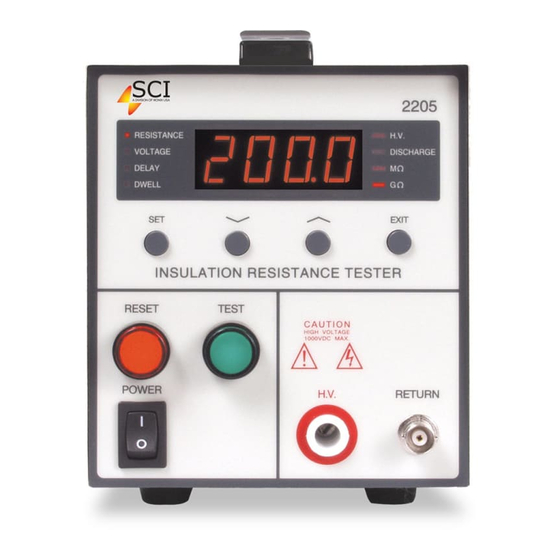
CONTROLS FRONT PANEL CONTROLS 2205 RESISTANCE H.V. VOLTAGE DISCHARGE Ω DELAY Ω DWELL EXIT INSULATION RESISTANCE TESTER RESET TEST CAUTION HIGH VOLTAGE 1000VDC MAX. POWER H.V. RETURN POWER SWITCH: Rocker-style switch with international ON ( | ) and OFF (0) markings. - Page 22 CONTROLS 2205 RESISTANCE H.V. VOLTAGE DISCHARGE Ω DELAY Ω DWELL EXIT INSULATION RESISTANCE TESTER RESET TEST CAUTION HIGH VOLTAGE 1000VDC MAX. POWER H.V. RETURN ∧) UP ARROW ( : Use this key to increment numeric values in the setup mode.
- Page 23 CONTROLS 2205 RESISTANCE H.V. VOLTAGE DISCHARGE Ω DELAY Ω DWELL EXIT INSULATION RESISTANCE TESTER RESET TEST CAUTION HIGH VOLTAGE 1000VDC MAX. POWER H.V. RETURN 14. DWELL LED INDICATOR: This indicator illuminates when dwell time is displayed in either test or setup mode.
- Page 24 CONTROLS REAR PANEL CONTROLS F1A 250V 115V 230V 1A MAX., 50Hz/60Hz INTERLOCK FAIL TEST PASS RESET PROCESSING CAL. 1. VENTILATION: To cool the instrument. 2. INPUT POWER SWITCH: Line voltage selection is set by the position of the switch. In the down position it is set for 115 volt operation, in the up position it is set for 230 volt operation.
-
Page 25: Quick Start
QUICK START QUICK START This quick start guide presumes the operator has some familiarity with hipot testing and desires to use the "default" settings on the instrument. The default settings shown will remain in memory unless you choose to override them with your own test program. The instrument default settings are as follows: DEFAULTS •... - Page 26 QUICK START see the model number briefly appear on the LED readout as well as the firmware version number and then clear itself. F). If the instrument DEFAULTS are acceptable, then be sure to connect the appropriate test leads to the device under test (DUT) or test fixture. Be certain that the unit is connected to suitable power with a known good ground before energizing this instrument, then connect the return lead first (black) to the test fixture or item followed by the high voltage output lead (red).
-
Page 27: Setup
SETUP Model 2205 SETUP INSTRUCTIONS FOR Check to be sure the correct input line voltage has been selected on the rear panel (115 volts AC or 230 volts AC). Connect the power input plug into its socket on the rear panel of the instrument. - Page 28 SETUP Use the Up/Down Arrow keys to enter the desired resistance low limit, then press the EXIT key to exit to the run mode or toggle to another setting using the SET key. The limit is set in either gigohms or megohms as shown by the two LED indicators to the lower right of the numeric display.
- Page 29 SETUP 4. To set the Dwell function Press the SET key until the Dwell LED is illuminated and flashing. Dwell time is the length of time the instrument will apply the programmed test voltage. Use the Up/Down Arrow keys to set the dwell time, then press the EXIT key to exit to the run mode or toggle to another setting using the SET key.
-
Page 30: Operation
OPERATION OPERATING INSTRUCTIONS FOR MODEL 2205 1. After the instrument's test parameters are programmed, connect the appropriate test leads to the device under test (DUT) or test fixture. Be certain the unit is connected to suitable power with a known good ground before energizing this instrument. Then connect the return lead first to the test fixture or the DUT followed by the high voltage lead. - Page 31 OPERATION Total cycle time is the delay time plus the dwell time. At the completion of the dwell time, the instrument will ‘ chirp’ to signal the operator that the test cycle has been completed. Press the TEST switch to initiate another test. Displayed Messages The following message is displayed when the IR test results in a DUT measurement that is greater than the range of the instrument.
- Page 32 OPERATION The following message is displayed when the unit detects a ground current that exceeds the GFI threshold. The high voltage power supply of the instrument is internally referenced to earth ground. The leakage current measuring circuits monitor only currents that flow through the Return lead.
-
Page 33: Remote I/O
REMOTE I/O REMOTE I/O All inputs are connected through the 9-pin “ D” type connector mounted on the back panel of the unit. This connector mates with the standard 9-pin “ D” subminiature female connector included with the unit. For best performance, a shielded cable should be used. To avoid ground loops, the shield should not be grounded at both ends of the cable The remote interface includes a SAFETY INTERLOCK. - Page 34 REMOTE I/O Remote I/O Connection Pins 1 and 6 provide the PROCESSING signal. Pins 6 and 7 provide the PASS signal. Pins 8 and 9 provide the FAIL signal. A description of the output relay operation follows: PROCESSING – The relay contact closes the connection between pin 1 and pin 6 while the instrument is performing a test.
-
Page 35: Calibration
Release the “ Cal.” button. The screen will display “ 2205” , the firmware version number and then “ Cal.” . • Step 4. Use the ∧ (up) or ∨ (down) button to select “ HI” . -
Page 36: Replacement Parts List
REPLACEMENT PARTS LIST REPLACEMENT PARTS LIST Rev. A ECO 5590 Part Number Qty. Reference Description Designator 102-045-901 Return Cable 102-055-913 High Voltage Cable 125-013-001 Power Cord (6 ft.) 175-974-003 Tilt-Up Leg Kit 330-112-001 Power Switch 330-113-001 Test Switch 330-113-002 Reset Switch 575-705-001 Red LED 99-10040-01... -
Page 37: Schematic Index
SCHEMATIC INDEX SCHEMATIC INDEX Drawing Number Description Reference Pages Designator S02205 Wiring Diagram 2205 S99-10259 Main Control Board CON2205 S99-10260 High Voltage Board DCP1KV S99-10261 Display Board DSP2205...
Need help?
Do you have a question about the 2205 and is the answer not in the manual?
Questions and answers