Advertisement
15 & 25PFR PLUNGER PUMP SERVICE MANUAL
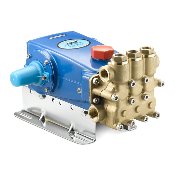
15 FRAME SPLIT MANIFOLD
25 FRAME SPLIT MANIFOLD
Optimum performance of the pump is dependent upon the entire liquid system and will be obtained only
with the proper selection, installation of plumbing, and operation of the pump and accessories.
SPECIFICATIONS
: Maximum speci cations refer to individual attributes. It is no t
implied that all maximums can be performed simultaneousl y. If more than one
maximum is considered, check with your CAT PUMP S supplier to con rm the proper
performance and pump selection. Refer to individual pump Data Sheets for complete
speci cations, parts list and exploded view.
LUBRICATION:
Fill crankcase with special CAT PUMP oil per pump speci cations
(15 P F R- 42 oz. , 25P FR-8 4 oz.). DO NOT R UN P UMP WI THO UT OI L IN CR ANK C ASE .
Change initial ll after 50 hours running period. Thereafter, change oil every 3 month s
or 500 hour intervals. Additional lubrication may be required with increased hours
of operation and temperature.
PUMP ROTATION : Pump was designed for forward rotation to allow optimum lubrica-
tion of the crosshead area. Reverse rotation is acceptable if the crankcase oil level
is increased slightly above center dot to assure adequate lubrication.
PULLEY
SELECTION:
Select size of motor pulley required to deliver the desired
ow from Horsepower Requirement and Pulley Selection Chart (refer to Tec h
Bulletin 003 or individual Data Sheet).
MOTOR SELECTION:
The motor or engine driving the pump must be of adequate
horsepower to maintain full RPM when the pump is under load. Select the electric
motor from the Horsepower Requirement Chart according to required pump
discharge
ow, maximum pressure at the pump and drive losses of approximately
3-5% . Consult the manufacturer of gas or diesel engine for selection of the proper
engine size.
MOUNTING:
Mount the pump on a rigid, horizontal surface in a manner to permit
drainage of crankcase oil. An uneven mounting surface will cause extensive
damage to the pump base. To minimize piping stress, use appropriate
hose to inlet and discharge
port s . Use the correct belt; make sure pulleys are
aligned. Excessive belt tension may be harmful to the bearings. Hand rotate pump
before starting to be certain shaft and bearings are free moving.
LOCATION : If the pump is used in extremely dirty or humid conditions, it is recommen d-
ed pump be enclosed. Do not store or operate in excessively high temperatur e
areas or without proper ventilation.
INLET CONDITIONS:
Refer to complete Inlet Condition Check-List
before starting system. DO NOT STARVE
Temperatures above 130°F are permissible. Add 1/2 PSI inlet pressure per eac h
degree F over 130°F. Elastomer or RPM changes may be required. See Tec h
Bulletin 002 or call CAT PUMPS for recommendations.
C. A .T. : Ins tallation of a C. A. T. (C aptive Acce leration Tu be) is recommended in
applications with stre s s ful inlet conditions s uch a s high temperatures , booste r
pump feed, long inlet lines or quick closing valves.
All systems require both a primary pressure regulating device (i.e., regulator, unloader) and a secondary pressure safety relief device (i.e., pop-o valve, safety valve).
Failure to install such relief devices could result in personal injury or damage to the pump or to system components. CAT PUMP S does not assume any liability or responsibilit y
for the operation of a customer's high pressure system
Pijttersen B.V.
Postbus 262,
Transportwei 26, 8501 ZP Joure
The Netherlands
:
:
INSTALLATION AND START-UP INFORMATION
exibl e
in this manual
THE PUMP OR RUN DRY .
WARNING
.
Tel.: +31 (0)513-414040
8500 AG Joure
Fax: +31 (0)513-414066
E-mail : info@pijttersen.nl / info@catpumps.nl
Internet : www.pijttersen.nl / www.catpumps.nl
1530, 1531, 1540, 1540E, 1560
2510, 2511
DISCHARGE
CONDITIONS:
OPEN ALL VALVES BEFORE
avoid deadhead overpressure condition and severe damage to the pump or sy
Install a Pulsation Dampenin g device on the discharge head or in the discharge line
as close to the head as possible. Be certain the pulsation dampener (Prrrrr-o-lator) is
properly precharged for the system pressure (refer to individual Data Sheet)
A reliable Pressur e Gaug e should be installed near the discharge outlet of the
high pressure manifold. This is extremely important for adjusting pressure regulating
devices and also for proper sizing of the nozzle or restricting ori ce. The pump is
rated for a maximum pressure; this is the pressur e which would be read at the
discharge manifold of the pump
, NOT AT THE GUN OR NOZZLE.
Use PTFE thread tape or pipe thread sealant (sparingly) to connect accessories or
plumbing. Exercise caution not to wrap tape beyond the last thread to avoid tape
from becoming lodged in the pump or accessories. This condition will cause a mal-
function of the pump or system.
PRESSURE
REGULATION:
All systems require both a primary pressure regulating
device (i.e., regulator, unloader) and a secondary pressure safety relief device (i.e.,
pop-o valve, safety valve). The primary pressure device must be installed on the
discharge side of the pump. The function of the primary pressure regulating device
is to protect the pump from over pressurization, which can be caused by a plugged
or closed o discharge line. Over pressurization can severely damage the pump,
other system components and can cause bodily harm. The secondary safety relief
device must be installed in-line between the primary device and the pump or on
the opposite side of the manifold hea d. This will ensure pressure relief of the
system if the primary regulating device fails. Failure to install such a safely device
will void the warranty on the pump.
When the high pressure system is left running with the trigger gun o , the by-pass
liquid can be routed to drain or to the pump inlet. If routed to the pump inlet, the
by-pas s liqui d ca n quic kl y dev elop exc ess ive heat and result in damage to
the pump . A THERMO
VALVE installed in the by-pass line is recommended to
protect the pump. An AUTO SHUT-OFF ASSEMBLY may also be used.
NOZZLES:
A worn nozz le will result in loss of pres sure. Do not adjust press ure regulat-
ing device to compensate. Replace nozzle and reset regulating device to syste m
pressure.
PUMPED LIQUIDS: Some liquids may require a ush between operations or befor e
storing. For pumping liquids other than water, contact your CA
STORING:
For extended storing or between use in cold climates, drain all pumped
liquids from pump and ush with antifreeze solution to prevent freezing an d
damage to the pump. DO NOT RUN PUMP WITH FROZEN LIQUID (refer to Tech
Bulletin 083).
STARTING
SYSTEM
to
s tem.
.
T PUMP S supplier.
Advertisement
Table of Contents

Subscribe to Our Youtube Channel
Related Manuals for CAT Pumps 1530


Summary of Contents for CAT Pumps 1530
- Page 1 F over 130°F. Elastomer or RPM changes may be required. See Tec h storing. For pumping liquids other than water, contact your CA T PUMP S supplier. Bulletin 002 or call CAT PUMPS for recommendations. STORING: For extended storing or between use in cold climates, drain all pumped C.
-
Page 2: Servicing The Valves
Inspect and service all system accessories on the same schedule as your pump. SERVICING THE VALVES Disassembly 1. Models 1530 1531, 1540, 1540E, 2510, 2511: Remove the hex 7. Place spring on valve and snap the spring retainer onto seat. valve plugs with o-ring. - Page 3 NOTE: Two screwdrivers on opposite sides of the manifold 5. Models 1530, 1531, 1540, 1540E, 1560: Use a screwdriver to may be used to assist separation. remove Lo-Pressure seal (LPS) from backside of manifold.
- Page 4 8. Models 1530, 1531, 1560, 2510, 2511: Place the female adapter with flat side down, “V” side up into each seal chamber. 9. Models 1530, 1531, 2510, 2511: Fit two new V-Packings together. Model 1560: Fit three new V-Packings together.
- Page 5 NOTE: It is highly recommended that antiseize lubricant (PN6119) be applied to the threads on all stainless steel 7. Models 1530, 1531, 1560, 2510, 2511: Install gaskets first, components to prevent galling. then o-rings and back-up-rings onto plunger retainers.
-
Page 6: Preventative Maintenance Check-List
Higher temperature liquids tend to vaporize and require positive heads and * If other than CAT PUMPS special custom-blend multi-viscosity ISO68 C. A.T. to assure adequate inlet supply. hydraulic oil is used, change cycle should be every 300 hours. - Page 7 Handy Formulas to Help You HOSE FRICTION LOSS PRESSURE DROP IN PSI PER 100 FT OF HOSE WITH TYPICAL WATER FLOW RATES Q. How can I find the RPM needed to get specific GPM Water* Hose Inside Diameters, Inches Flow (Gallons Per Minute) I want? 5/16 1"...
-
Page 8: Diagnosis And Maintenance
CAT PUMPS are very easy pumps to service and require far less frequent service than most pumps. Typically, only common tools are required, making in-field service convenient, however, there are a few custom tools, special to certain models, that do simplify the process. This service manual is designed to assist you with the disassembly and reassembly of your pump.
Need help?
Do you have a question about the 1530 and is the answer not in the manual?
Questions and answers