
Related Manuals for CAT Pumps 1XP Series


Summary of Contents for CAT Pumps 1XP Series
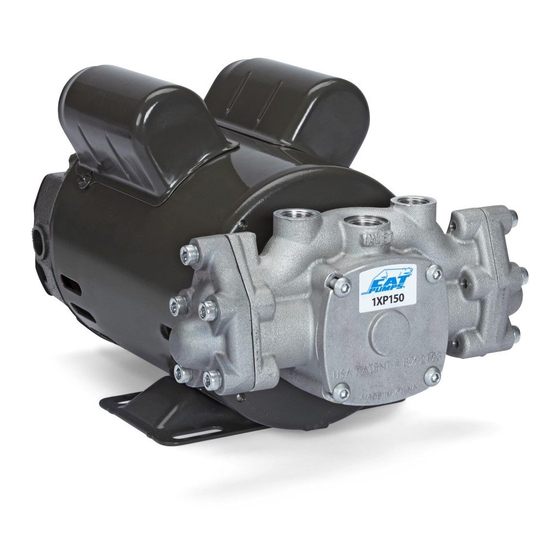
- Page 1 1XP Series Plunger Pump Installation, Operational and Repair Manual Product Quality, Reliability and Support You Expect www.catpumps.com...
-
Page 2: Table Of Contents
Preventative maintenance Troubleshooting (i.e., problem – cause – solution) Flow and Pressure Cat Pumps Warranty Safety Hazards A. FLAMMABLE OR EXPLOSIVE LIQUID HAZARD Do not operate pump with flammable or explosive liquids unless extraordinary safety precautions are observed. Leaks of flammable or explosive liquids, if exposed to elevated temperatures, static electricity, sparks or other hazards, will result in flame or possible explosion, causing serious personal injury, death or property damage. - Page 3 A. ELECTRICAL SHOCK HAZARD Do not service pump or electrical equipment while energized. Electricity can cause personal injury, death or property damage. 1. Adhere to “Lock Out” and “Tag Out” procedures for electrical equipment. 2. Before commencing pump service, turn power supply off. 3.
- Page 4 G. OXYGEN HAZARD Do not charge Prrrrr-O-Lators (Pulsation Dampeners) with oxygen. Oxygen may cause an explosion causing Continued personal injury, death or property damage. 1. Use nitrogen only when charging pulsation dampeners, DO NOT USE OXYGEN. 2. Use proper charging tools to charge pulsation dampeners. 3.
- Page 5 E. LIFTING DEVICE HAZARD Do not lift pump with unsuitable lifting devices. Use of unsuitable lifting devices may cause pump to fall Continued resulting in personal injury, damage to pump and/or pump with drive/base plate. 1. Lifting eyes installed on the pump must be used only to lift the pump. 2.
-
Page 6: Pump Models And Pump/Motor Assemblies
Technical Features There are eight (8) cams available for the 1XP Series Pumps. Each cam is numbered from 1 to 8, with the smallest number 1 indicating the lowest flow starting at 0.50 gpm, up to the largest number 8 indicating 2.00 gpm. If a label has been removed or destroyed, simply remove bearing cover and check stamped number on cam. - Page 7 Electrical power connection: Power Cord Connection 1.3 Connect to power source for AC 1.4 Connect to power source for DC (induction) motors 8133, 8135 and 8147 (permanent magnet) motor 8136, 8139 (115/208-230VAC). (120 Volt - rectified) and 8138 (240 Volt - rectified) Plumbing connection: NOTE: Standard pump to motor mounting is shown in figure 1.5 (inlet port facing out).
-
Page 8: (Electrical Power Connection And Plumbing Connection) Preliminary Inspection
Preliminary Inspection Parts List After inlet hose, discharge hose and/or accessories have been Item Part installed to ports of pump crankcase follow the preliminary steps as Number Matl Description outlined below prior to startup. 76801 Crankcase 2.1 Ensure all hoses and fittings are tight. 8133 Motor, 1/3 HP (AC), Keyed Shaft 8135... -
Page 9: Exploded View
Exploded View AC Motor (Threaded Shaft) DC Motor (Keyed Shaft) AC Motor (Keyed Shaft) -
Page 10: Pump Disassembly
Pump Disassembly Do not service pump or electical equipment while energized. Electricity can cause personal injury, death or property damage. 1. Adhere to “Lock Out” and “Tag Out” procedures for electrical equipment. 2. Before commencing pump service, turn power supply off. 3. - Page 11 NOTICE For Threaded Shaft Units: If old shaft seal cannot be removed, it may require removing motor cover. (See Service Bulletin 002) 5.7 Place 1/2" open wrench behind cam 5.8 Unthread threaded cam from motor Old Shaft Seal (8) onto motor shaft. Position tips of shaft spanner-wrench into two holes of cam and turn to loosen.
- Page 12 Pump Disassembly continued NOTE: Inlet valve, discharge valve, high pressure seal and plunger are identical in both cylinder heads. 5.14 Use a 5mm allen wrench to remove 5.15 Insert the short end of an allen wrench 5.16 Pivot 5M allen wrench against top five (5) M6x30 screws (13) holding head to remove discharge valve assembly.
-
Page 13: Pump Reassembly
Pump Reassembly 6.1 Lubricate and install slinger o-ring (11) 6.2 Lubricate and install motor flange 6.3 Lubricate and install shaft seal (10) into motor flange by sliding over motor o-ring (12) onto the motor flange. with stainless steel flange facing out shaft. - Page 14 Pump Reassembly continued 6.7 Lubricate and install woodruff key (9) 6.8 Lubricate and install cam (8) over 6.9 Install retaining ring (7) into snap into motor shaft keyway. (Keyed Shaft motor shaft and key. Position cam (8) ring groove on motor shaft to secure only).
- Page 15 6.16 Install spacer (19) small diameter down 6.17 Install spring (18) over spacer (19) and 6.18 Install washer (17) with curved surface into inlet valve (20). on to inlet valve (20). down on to spring (18). 6.19 Apply Loctite®242® to M6 threads on 6.20 Assemble the discharge valve as follows: 6.21 Place valve (25) cupped side over the plunger rod.
- Page 16 Pump Reassembly continued 6.25 Lubricate and install o-ring (15) into 6.26 Position head cover (14) onto 6.27 Use a 5mm allen wrench to torque to head cover. Repeat for other cylinder crankcase body (1) and hand thread 102 in-lbs in sequence as shown. head.
-
Page 17: Dc Motor (8136) Brush Replacement
DC Motor (8136 only) Brush Replacement DISASSEMBLY REASSEMBLY 7.1 Place flat tip of screwdriver between the 7.6 Position wire lead into opening of motor top of the white retaining clip and end with brush and attaching spring down cover and pry upwards to provide small into opening with brass end facing up. -
Page 18: Torque Specifications And Repair Tools
Water leaks operating condition. Perform the service Plumbing and inspection scheduled in the table. Use only genuine Cat Pumps parts or kits Seal change when performing repairs. Inlet valve change Discharge valve change... -
Page 19: Flow And Pressure
Flow and Pressure 1XP Pump with AC Induction Motor AC Induction Motor – 60 Hz, 120V (1750 rpm) AC Induction Motor – 50 Hz, 240V (1450 rpm) Pump Pump Max PSI Max PSI Assembly Assembly 1XP050.031 0.40 1XP050.031 0.75 1XP075.031 0.60 1XP075.031 0.85... -
Page 20: Cat Pumps Warranty
(available on-line at www.catpumps.com) for the Product. Cat Pumps makes no warranty on standard wear items such as, but not limited to, seals, valves, seats and o-rings. This warranty does not cover, and Cat Pumps shall not be liable for, defects...
Need help?
Do you have a question about the 1XP Series and is the answer not in the manual?
Questions and answers