
Related Manuals for CAT Pumps 2560


Summary of Contents for CAT Pumps 2560
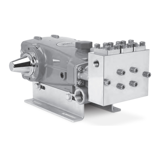
- Page 1 SERVICE MANUAL 25 FRAME PLUNGER PUMPS PUMP MODELS INCLUDED 2560 2565 2560 BH 2565 BH Product Quality, Reliability and Support You Expect www.catpumps.com...
-
Page 2: Table Of Contents
Table of Contents Safety Symbols IMPORTANT SAFETY INSTRUCTIONS Safety Symbols It is the responsibility of the user to read and understand all General Safety Information instructions, important safeguards and safety precautions before Seal & Valve Kits operating or servicing any pump. Failure to do so may result in Service Intervals property damage, personal injury or death. -
Page 3: General Safety Information
General Safety Information A. FLAMMABLE OR EXPLOSIVE LIQUID HAZARD Do not operate pump with flammable or explosive liquids unless extraordinary safety precautions are observed. Leaks of flammable or explosive liquids, if exposed to elevated temperatures, static electricity, sparks or other hazards, will result in flame or possible explosion, causing serious personal injury, death or property damage. - Page 4 General Safety Information and Symbols F. OVER PRESSURIZATION HAZARD CONTINUED Do not operate high-pressure pumping system unless extraordinary safety precautions are observed. A high-pressure pumping system can deadhead or over pressurize causing serious personal injury and property damage. 1. All high-pressure systems require a primary pressure regulating device (e.g., regulator or unloader) and a secondary pressure safety relief device (e.g., pop-off valve, safety valve, rupture disc) to assure proper pressure setting and overpressure protection.
- Page 5 1. Fill pump crankcase to specific capacity indicated on data sheet or service manual prior to startup. 2. Cat Pumps premium custom-blend oil is available worldwide in 21-ounce bottles, (single and 12-pack cases), 2.5 gallon jugs (single and 2-pack) or 30 gallon drums. Use of other oils may void the warranty.
-
Page 6: Seal & Valve Kits
The seals on our pumps, operating under normal conditions, will perform for a minimum of 1500 hours, with most lasting much longer. The valves typically perform for 3000 hours, with many lasting much longer. Cat Pumps always recommends replacing these items as a kit since components usually wear at about the same rate. -
Page 7: Seal & Valve Kit Pump Diagram
Seal & Valve Kit Pump Diagram SEAL KIT 2560 , 2560 BH: PN 76853 | Qty 1 2565 , 2565 BH: PN 76854 | Qty 1 VALVE KITS PN 31292 | Qty 1 LOW-PRESSURE VALVE KIT SEAL ASSEMBLY 31292 V-PACKINGS... -
Page 8: Servicing The Seals
Servicing the Seals MANIFOLD AND SEAL REMOVAL NOTE: One (1) seal kit is required to repair the pump (see data sheet PN 99DAT090). NOTICE: The discharge manifold is very heavy so use caution. Be sure to properly support the bottom of the manifold to avoid injury. - Page 9 Servicing the Seals MANIFOLD AND SEAL REMOVAL 1.09 Use a 10 mm hex socket to remove the 1.10 Using a rubber mallet, tap the manifold to 1.11 Insert two (2) flat tip screwdrivers on opposite four (4) HSH screws from the inlet manifold. create a separation between the crankcase sides to pry the manifold away from the and the manifold.
- Page 10 Servicing the Seals MANIFOLD AND SEAL REMOVAL NOTICE: Be careful not to score the inside of the manifold. 1.18 Use a flat tip screwdriver to pry the low- 1.19 Inspect the inside diameter of the low- pressure seal upward and remove. pressure seals for wear or damage.
-
Page 11: Plunger Removal
Servicing the Seals PLUNGER REMOVAL 1.20 Remove seal retainers from crankcase 1.21 Remove low-pressure seal washer. 1.22 Seal retainer can be separated to remove and housing. inspect the wicks. Replace as needed (wicks not included in the seal kit). 1.23 Using a 14 mm combination wrench, loosen 1.24 Before completely removing the plunger 1.25 Remove the plunger retainer from the the plunger retainer. -
Page 12: Plunger Reassembly
Servicing the Seals PLUNGER REASSEMBLY 1.32 Look for stepped side of plunger. This side 1.29 Install barrier slinger with dish side facing 1.31 Replace plunger retainer O-ring with new one goes towards the pump crankcase. away from crankcase. from seal kit and apply a lubricant to outside surface. -
Page 13: Seal Installation
Servicing the Seals SEAL INSTALLATION NOTICE: Examine manifolds, and male and female adapters for grooves, pitting or wear. Replace as needed. 1.41 Flip inlet manifold over so that valve spacer 1.39 Apply a lubricant to the outside surface of the 1.40 One side of the low-pressure seal has a bores are facing up. -
Page 14: Manifold Reassembly
Servicing the Seals MANIFOLD REASSEMBLY 1.50 Place a drop of Loctite® 242® on the threaded 1.48 Rotate crankshaft so outside two plungers are 1.49 Install inlet manifold by hand, ensuring even end of the four (4) HSH screws and install by even at furthest distance from crankcase. -
Page 15: Servicing The Valves
Servicing the Valves VALVE REMOVAL NOTE: One (1) valve kit is required to repair the pump (see data sheet PN 99DAT090). 2.01 Use a 10 mm hex socket to remove the four (4) 2.02 Using a small flat tip screwdriver, tap between 2.03 Remove the valve plug by hand. -
Page 16: Valve Disassembly
Servicing the Valves VALVE DISASSEMBLY 2.08 Insert a flat tip screwdriver through discharge 2.09 Remove discharge spring retainer by hand. 2.10 Inspect discharge valve spring retainer for spring retainer just above discharge valve. cracks, excessive wear or damage. Twist to create a small gap between discharge spring retainer and discharge valve seat. - Page 17 Servicing the Valves VALVE DISASSEMBLY 2.18 Remove inlet spring retainer by hand. 2.19 Inspect inlet valve spring retainer for cracks, 2.20 Inspect spring for proper tension or any excessive wear or damage. damage. 2.21 Inspect tapered surface of inlet valve for wear, 2.22 Inspect tapered surface of inlet valve seat for 2.23 Inspect inlet valve seat O-ring for cuts, nicks or pitting or damage.
-
Page 18: Valve Reassembly
Servicing the Valves VALVE REASSEMBLY 2.24 Replace inlet valve O-ring. 2.25 Hold inlet valve seat with tapered surface 2.26 Place inlet valve onto inlet valve seat with facing up. tapered surface facing down. 2.27 Place spring onto stepped side of inlet valve. 2.28 Place inlet valve spring retainer onto inlet 2.29 Push assembly together until it snaps into valve seat. - Page 19 Servicing the Valves VALVE REASSEMBLY 2.33 Place spring onto stepped side of discharge 2.34 Place discharge valve spring retainer onto 2.35 Push assembly together until it snaps into valve. discharge valve seat. place. 2.36 Apply a lubricant to the outside surface of the inlet valve seat O-ring.
-
Page 20: Valve Installation
Servicing the Valves VALVE INSTALLATION 2.37 Apply a lubricant to the outside surface of the 2.38 Insert valve assembly into manifold and press 2.39 Install valve plug backup ring, then O-ring, discharge valve seat O-ring. into place. and apply a lubricant to outside surface. NOTICE: Valve plug O-ring faces down when installed in the manifold. -
Page 21: Crankcase Component Inspection
If contamination is suspected, inspect and replace the seals in the pump manifold, then clean out the inside of the crankcase and change the oil. Spot-check the following areas for signs of leaks and contact Cat Pumps or a local distributor for servicing crankcase if needed. Oil Bubble Gauge... -
Page 22: Reference Information
Cat Pumps recommends using our custom-blend premium grade hydraulic oil formulated to meet Cat Pumps specifications. For best results, perform an initial oil change after the first 50 hours of operation and every 500 hours thereafter. -
Page 23: Torque Chart
Reference Information TORQUE CHART PUMP ITEM THREAD TOOL SIZE TOOL PART NUMBER TORQUE IN-LBS FT-LBS Plunger Retainers M14 Hex — 10.0 Inlet Manifold Screws M10 Allen — 40.0 Discharge Manifold Screws M10 Allen — 40.0 Valve Plug Cover Screws M10 Allen —... -
Page 24: Diagnosis And Maintenance
For International Inquiries go to www.catpumps.com and navigate to the “Contact” link. ©2021 Cat Pumps. All written and visual data contained in this document reflects the latest product information available at the time of publication. Cat Pumps reserves the right to make changes at any time without notice.
Need help?
Do you have a question about the 2560 and is the answer not in the manual?
Questions and answers