Table of Contents
Advertisement
Advertisement
Table of Contents

Related Manuals for Rhymebus RM6 Series


Summary of Contents for Rhymebus RM6 Series
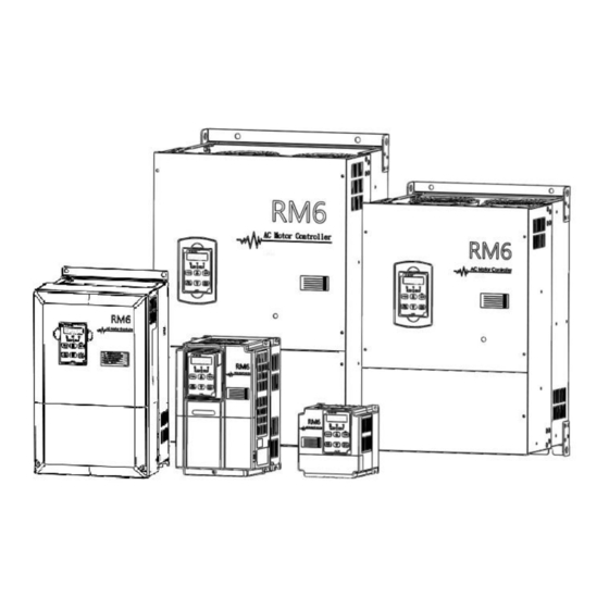
- Page 1 VARIABLE FREQUENCY DRIVE Operation Manual ISO 9001:2008 RM6 series (9426)
- Page 2 Quality․Satisfaction․Improvement․Innovation 2012.5.14 Edition http://www.rhymebus.com.tw 2018.10.24 Revised...
- Page 3 PREFACE Thank you for using RHYMEBUS RM6 series (9426) drive. For proper operations and safety purposes, please do read and follow specific instructions contained in this manual before using the product. The manual shall be placed on the top of the machine, and all the setup parameters and reference numbers must be properly recorded in Attachment 3 to facilitate future maintenance and repairs.
- Page 4 Please note the surrounding temperature shall not exceed 50°C when the installation needs to be placed inside the control panel. d. For the environment of storage and installation, please follow the instructions of the environmental conditions illustrated in the sections of the common specification of RM6 series (9426).
- Page 5 CAUTION a. The RM6 series (9426) are designed to drive a three-phase induction motor. Do Not use for single-phase motor or other purposes. b. The main circuit and control circuit must be wired separately; control circuit must use a shielded or twisted-pair shielded wires to avoid possible interferences.
- Page 6 Operation DANGER a. Do Not open or remove the cover while power is on or during the operation. Do close up the cover before powering on the drive. Do Not remove the cover except for wiring or periodic inspection when power off. b.
- Page 7 2. These devices are intended for use in Pollution Degree 2 environments. 3. Maximum surrounding air temperature 50C for RM6 series (9426). 4. Short circuit rating "Suitable For Use On A Circuit Capable Of Delivering Not More Than 5000 rms Symmetrical Amperes, 240V Maximum for 200V class."...
- Page 8 Compliance with UL standards and CSA standards (cUL-listed for Canada) (continued) CAUTION Three-Phase 400V Series Model number Fuse type Fuse current rating (A) RM6-4001-9426 RM6-4002-9426 Class RK5 RM6-4003-9426 RM6-4005-9426 RM6-4007-9426 RM6-4010-9426 Class T RM6-4015-9426 RM6-4020-9426 6. Main circuit terminal wiring "Use 60C / 75C Cu wire only."...
- Page 9 Compliance with UL standards and CSA standards (cUL-listed for Canada) (continued) CAUTION 400V Class Series Wire size AWG (mm Model number Input Output Grounding (R/L1, S/L2, T/L3) (U/T1, V/T2, W/T3) RM6-4001-9426 18 (0.8) 18 (0.8) 18 (0.8) RM6-4002-9426 RM6-4003-9426 16 (1.3) 16 (1.3) 16 (1.3) RM6-4005-9426...
- Page 10 INTRODUCTIONS Features a. PID control function for constant pressure. b. 4-pumps parallel control is available. Parallel control of 2 unit pumps to remain the constant pressure in pipelines. c. 3 operation modes (E-mode, F-mode, M-mode) to select the maximum efficiency and energy saving. d.
-
Page 11: Table Of Contents
Chapter 2 Installation and Confirmation Table of Contents Chapter 1 Cautions Before Installation --------------------------------- 1-1 Product Verification ----------------------------------------------------------------------- 13 1-2 Standard Specifications ----------------------------------------------------------------- 14 1-3 Common Specifications ----------------------------------------------------------------- 18 Chapter 2 Installation and Confirmation ------------------------------- 2-1 Basic Equipment --------------------------------------------------------------------------- 21 2-2 Installing the Drive ------------------------------------------------------------------------- 21 2-3 Descriptions of Terminal and Wiring Diagram ----------------------------------- 25 2-4 Wiring Diagram and Setting for Single-pump and Multi-pump... -
Page 12: Table Of Contents
Chapter 2 Installation and Confirmation Appendix F Selection of Zero-Phase Radio Frequency Filter ------------------------------------------------------------------------- Appendix G Selection of EMI Filter ------------------------------------- Appendix H Instruction of Remote Controller and External Display ------------------------------------------------------------- Appendix I Outline Dimension Drawing of Drives --------------- Attachment 1 Dimension of Keypad (KP-207) --------------------- Attachment 2 Default Value List ------------------------------------------ Attachment 3 Setting Memo------------------------------------------------ Attachment 4 Fault Display -------------------------------------------------... -
Page 13: Chapter 1 Cautions Before Installation
OUTPUT 3PH 200-240V 25A 0.1-400.0Hz Output Current & Capacity PGM NO. 9222-C(AZXXXXXX) Software Number SERIAL NO. BXXXXXXXX Product Serial Number Rhymebus Corporation, TAIWAN 1-1-2 The description of nomenclature: – 2 020 ( 1PH) 9426 Input Power Phase -1PH:Single-Phase Blank:Three-Phase Horse Power... -
Page 14: Standard Specifications
Chapter 2 Installation and Confirmation 1-1-3 Confirmation of Accessories One operation manual is inclusive. Please verify other accessories inclusively such as braking resistor, AC reactor, etc.. ※Please refer to the standard specifications to verify the product specifications with your requirements. 1-2 Standard Specifications 1-2-1 Single-Phase 100V Series Model name... - Page 15 Chapter 2 Installation and Confirmation 1-2-2 Three-Phase 200V Series Model name 2001/2 2001 2002 2003 2005 2007 2010 2015 □□□□ (RM6- -9426) Maximum applicable 0.5/0.4 1/0.75 2/1.5 3/2.2 5/3.7 7.5/5.5 10/7.5 15/11 motor (HP / kW) Rated output capability (kVA) Rated output current (A) Rated output voltage (V) Three-phase 200~240V...
- Page 16 Chapter 2 Installation and Confirmation Model name 2125 2150 2200 2250 - - - - □□□□ (RM6- -9426) Maximum applicable - - - - 125/90 150/110 200/160 250/200 motor (HP / kW) Rated output capability - - - - (kVA) -...
- Page 17 150% of drive rated output current for 1 min. Cooling method Fan cooling Applicable safety - standards Protective structure IP00 (IP20 OPTION) Weight / Mass(kg) ※The weight illustrated in the standard specifications of RM6 series (9426) does not include the weights of AC reactor(ACL) and DC reactor(DCL).
-
Page 18: Common Specifications
Chapter 2 Installation and Confirmation 1-3 Common Specifications 1-3-1 The Features of Control and Operation ․Voltage vector sinusoidal PWM control (V/F control). Control method ․Switching frequency: 800Hz~15KHz. Range of 0.1~400.00Hz frequency setting Resolution ․Digital Keypad: 0.01Hz of frequency ․Analog signal: 0.06Hz / 60Hz setting Resolution 0.01Hz... - Page 19 Chapter 2 Installation and Confirmation Operation method F_051=0(Operation Condition Memory) 4 sets programmable input terminals: X1~X4 Multi-function inputs Refer to the function setting description of F_052~F_055 ․Vin – GND: DC 0~10V ․Iin – GND: DC 4~20mA / 2~10V or DC 0~20mA / 0~10V Analog inputs Refer to the function setting description of F_040, F_041, and...
- Page 20 Chapter 2 Installation and Confirmation Non-corrosive or non-conductive, or non-explosive gas or Atmosphere liquid, and non-dusty Surrounding -10°C (14°F) ~ +50°C (122°F) (Non-freezing and non-condensing) temperature Storage -20°C (-4°F) ~ +60°C (149°F) temperature Relative humidity 90% RH or less (No-condensing atmosphere) Vibration Less than 5.9m/sec²...
-
Page 21: Chapter 2 Installation And Confirmation
Please be cautious to the motor rated current that must not exceed the drive current. Note: RM6 series (9426) is only used for pump with three-phase induction motor control, and must not be used for single-phase motor. 2-2 Installing the Drive For the safe operation of the drive, please be cautious to the environmental conditions where the drive is going to be installed. - Page 22 Chapter 2 Installation and Confirmation 2-2-3 Arrangement: Due to the heat generated at the machine operation, the drive must be installed in the ventilate space. The installations of drive are shown as below figure 1 and figure 2: a. Internal cooling Correct Incorrect Outlet...
- Page 23 Chapter 2 Installation and Confirmation b. External cooling Correct Incorrect Outlet Outlet Outlet Outlet RM5G/P RM5G/P Drive Drive Drive Drive Guide RM5G/P RM5G/P Drive Drive Drive Drive Inlet Inlet Inlet Inlet Intlet Intlet Intlet Intlet Correct Incorrect Outlet Outlet Outlet Outlet RM5G/P RM5G/P...
- Page 24 Chapter 2 Installation and Confirmation 2-2-4 Specifications of Associated Accessories: The specifications of the accessories must be according to the specifications of the drive. Otherwise, the drive will be damaged and the life span of the drive will be shorten. Do Not add any power factor leading capacitor(RC, LC or other capacitance component) between the drive and motor to avoid any accidents.
-
Page 25: Descriptions Of Terminal And Wiring Diagram
2-3-1 Wiring Diagram Model: RM6-1001/2-1PH-9426 ~ RM6-1002-1PH-9426; RM6-2001/2-1PH-9426 ~ RM6-2002-1PH-9426 Braking Resistor(option) Main Circuit Terminals Control Terminals Induction Motor Single-Phase, 50/60Hz AC Power Input RM6 series (9426) Analog Output Terminal (DC 0~10V) Forward Reverse ※1 Multi-function Input Terminal 1 SINK... - Page 26 U/T1 R/L1 R/L1 Three-Phase, 50/60Hz V/T2 S/L2 S/L2 AC Power Input T/L3 W/T3 T/L3 RM6 series (9426) Analog Output Terminal (DC 0~10V) Forward Reverse ※1 Multi-function Input Terminal 1 SINK Multi-function Input Terminal 2 Multi-function Output Terminal Multi-function Input Terminal 3...
- Page 27 U/T1 R/L1 R/L1 Three-Phase, 50/60Hz S/L2 V/T2 S/L2 AC Power Input W/T3 T/L3 T/L3 RM6 series (9426) Analog Output Terminal (DC 0~10V) Forward Reverse ※1 Multi-function Input Terminal 1 SINK Multi-function Input Terminal 2 Multi-function Output Terminal Multi-function Input Terminal 3...
- Page 28 U/T1 R/L1 Three-Phase, 50/60Hz AC S/L2 V/T2 S/L2 Power Input T/L3 W/T3 T/L3 RM6 series (9426) Analog Output Terminal (DC 0~10V) Forward Reverse ※1 Multi-function Input Terminal 1 SINK Multi-function Input Terminal 2 Multi-function Output Terminal Multi-function Input Terminal 3...
- Page 29 U/T1 R/L1 Three-Phase, 50/60Hz AC S/L2 V/T2 S/L2 Power Input W/T3 T/L3 T/L3 RM6 series (9426) Analog Output Terminal (DC 0~10V) Forward Reverse ※1 Multi-function Input Terminal 1 SINK Multi-function Input Terminal 2 Multi-function Output Terminal Multi-function Input Terminal 3...
- Page 30 Chapter 2 Installation and Confirmation 2-3-2 SINK / SOURCE Definition There are two ways of connection for multi-function input terminals: SINK (NPN) logic SOURCE (PNP) logic SINK SINK SOURCE SOURCE Drive Drive +24V X1~X4 X1~X4 +24V (b) Jumper at 2,3 position; SOURCE mode (a) Jumper at 1,2 position;...
- Page 31 Chapter 2 Installation and Confirmation 2-3-4 Description of Terminals Main Circuit Terminals Type Symbol Function Description Single-phase; sinusoidal power (L,N) source 110V terminals. AC power source input terminals Power R,S,T Three-phase; sinusoidal power Source (L1,L2,L3) source input terminal. DC power External DC power source terminal.
- Page 32 Chapter 2 Installation and Confirmation b. Main Circuit Connection *(1) *(1) Grounding Grounding Motor MCCB Resistor *(1): The grounding marking of 100V series is PE. Terminal Tightening Grounding Tightening Model number screw torque terminal torque size lb-in (kgf-cm) size lb-in (kgf-cm) RM6- ______ -9426: 13.8 (15) 13.8 (15)
- Page 33 Chapter 2 Installation and Confirmation Grounding Grounding Jumper MCCB Motor Resistor Terminal Tightening Grounding Tightening Model number screw torque terminal torque size lb-in (kgf-cm) size lb-in (kgf-cm) RM6- ______ -9426: 20.8 (24) 13.8 (15) 2007, 2010, 2015, 4007, 4010, 4015, 4020, 4025 /L2 /L3 Grounding Grounding...
- Page 34 Chapter 2 Installation and Confirmation /T1 /T2 Grounding MCCB Grounding Motor Terminal Tightening Grounding Tightening Model number screw torque terminal torque size lb-in (kgf-cm) size lb-in (kgf-cm) RM6- ______ -9426: 104 (120) 104 (120) 2050, 2060, 2075, 4075, 4100, 4125 /L2 /L3 /T1 /T2 Grounding...
- Page 35 Chapter 2 Installation and Confirmation c. Voltage Selection Board of Cooling Fan ※RM6-4075-9426 above models have the voltage selection board shown in above figure when removing the main circuit terminal cover of the drive. Please carefully select the jumper position according to the power source (actual power voltage level) to avoid the burnout of the fan or the overheating of the drive.
- Page 36 Common terminal of Y1, Y2. FM_P Reserved e. Control Terminals and Switch for Multi-Pump Application Type Symbol Function Description ․Connect the RM6 series (9426) drives by Signal transmission terminal(+) transmission cable, when the drives Signal transmission control multiple pumps. ․Maximum parallel units:4 units terminal(-)
- Page 37 Chapter 2 Installation and Confirmation 2-3-5 Control Board (1) RM6-1001/2-1PH-9426 ~ RM6-1002-1PH-9426 RM6-2001-9426 ~ RM6-2005-9426 RM6-4001-9426 ~ RM6-4005-9426 SINK SINK I mode V mode SOURCE SINK SOURCE SOURCE DSW3 SINK FWD Y1 SOURCE X1 FM_P CN1: External indicator (DM-501) socket. CN3: Digital keypad (KP-207) socket.
- Page 38 Chapter 2 Installation and Confirmation (2) RM6-2007-9426 ~ RM6-2250-9426 RM6-4007-9426 ~ RM6-4600-9426 SINK I mode SINK V mode SOURCE SOURCE SINK SINK SOURCE SOURCE FM_P CN1: External indicator (DM-501) socket. CN2: Digital keypad (KP-207) socket. TB1: Input/Output terminals. TB3: Connection terminals for multi-pump control. JP1: Input impedance selection of Iin (close: 250Ω...
- Page 39 The setting of switching frequency is determined by F_081 800Hz Note: 2.5KHz 1. When the setting value of F_081 exceeds 4(10kHz) in RM6 series (9426) drive, recommending decrease the 5KHz output current or selecting the higher rated output Switching F_081 7.5KHz...
- Page 40 Chapter 2 Installation and Confirmation d.Recommend wire size and Molded Case Circuit Breaker(MCCB) Single-Phase 100V Series Input wire size Control circuit Grounding Model number MCCB (R/L1,S/L2,T/L3) wire size wire size RM6-_____-9426 (mm²) (mm²) (mm²) 1001/2-1PH 1001-1PH 0.75~1.25 1002-1PH Single-Phase 200V Series Input wire size Control circuit Grounding...
- Page 41 Chapter 2 Installation and Confirmation Three-Phase 400V Series Input wire size Control circuit Grounding Model number MCCB wire size wire size (R/L1,S/L2,T/L3) RM6-_____-9426 (mm²) (mm²) (mm²) 4001 4002 4003 4005 4007 4010 4015 4020 4025 4030 4040 4050 4060 0.75~1.25 4075 4100 4125...
-
Page 42: Wiring Diagram And Setting For Single-Pump And Multi-Pump Applications
Chapter 2 Installation and Confirmation 2-4 Wiring Diagram and Setting for Single-pump and Multi-pump Applications JP4: Input signal type selection of Iin Single Pump Control(F_015=1) JP1: Input impedance selection of Iin DSW3: Terminal resistor switch Drive #0 F_015: Selection of Pump Control Mode 1. -
Page 43: Chapter 3 The Setting Of Keypad
Chapter 3 The Setting of Keypad Chapter 3 The Setting of Keypad 3-1 Functions of Keypad (KP-207) KEYPAD Running 3-1-1 Indicators of Keypad Symbol Name Description 1.Indicate the lead drive. Lead drive 2.In multi-pump control modes, the indicator KEYPAD indicator will be off, when pressing RESET Setting pressure... - Page 44 Chapter 3 The Setting of Keypad UP key Operation key PROG key DOWN key FUN/DATA key OFF/RESET key 3-1-2 Keys of Keypad Symbol Name Description 1.Enter the function setting mode Function key PROG 2.Back to the monitor mode 1.Enter the parameter setting mode Function/ 2.Back to the function setting mode DATA...
-
Page 45: The Operation Of Keypad(Kp-207) And Monitor Mode
Chapter 3 The Setting of Keypad 3-2 The Operation of Keypad(KP-207) and Monitor Mode 3-2-1 Operation of Keypad The operation of the digital keypad includes fault messages and three modes. The switching methods are shown as below figure: Parameter setting mode Function setting mode Monitor mode KEYPAD... - Page 46 Chapter 3 The Setting of Keypad 3-2-2 Description of Monitor Mode There are seven displays can be selected in the monitor mode. Press to switch the display in accordance with below sequence under DATA monitor mode. User can determine one of seven displays as the main display from function F_006 (Selection of Main Display).
- Page 47 Chapter 3 The Setting of Keypad a. Select one of seven displays as the main display in accordance with the table of p.36 from F_006 (Selection of Main Display). b. Determine one of seven displays as the main display according to the application. When the parameter of function is completed without pressing key, the drive PROG...
- Page 48 Chapter 3 The Setting of Keypad 3-2-3 Description of Function Setting Mode In function setting mode, there are 155 functions (F_000 ~ F_154) can be selected for RM6 series (9426) drive, and the setting steps are as below: Operation Steps Display KEYPAD 1.In the monitor mode, press...
- Page 49 Chapter 3 The Setting of Keypad 3-2-6 Start / Stop Operation of Drive To start / stop the drive, the display must switch to monitor mode. (by default display) Operation Steps Display KEYPAD 1.In monitor mode, press key to start the drive. 設定值...
- Page 50 Restore Default Value: RM6 series (9426) drive provide four default values for using. User can according to the demand to restore default values. (Restore the default value of drive for 60Hz)
- Page 51 Chapter 3 The Setting of Keypad Select the parameter as an example, and the operation steps as below: Operation Steps Display ▼ ▲ 1.Press key selecting the function to KEYPAD F_154 (Default Setting) and then press key to DATA 設定值 實際值...
-
Page 52: Chapter 4 Parameter List
Chapter 4 Parameter List Chapter 4 Parameter List Range of Func. Name Description Unit Def50 Page Setting 0: Software version (9222-C) 1: Drive model number Drive 2: Drive running hours ─ ─ ─ F_000 Information 3: Drive power supplying time 4: Software checksum code 5: Reserved Rotation direction... - Page 53 Chapter 4 Parameter List Range of Func. Name Description Unit Def50 Page Setting 0.1~255.0 220.0 Base The voltage correspond to the base ─ F_012 0.1V Voltage frequency in V/F pattern. 0.1~510.0 380.0 0: Disable. 1: Shift the pump operation after the operating Pump time (F_024).
- Page 54 Chapter 4 Parameter List Range of Func. Name Description Unit Def50 Page Setting Communica The communication baud rate setting for ─ ─ F_026 -tion Baud multi-pump control systems. Rate Secondary Multi-function input terminals select the 0.0~ ─ F_027 Acceleration secondary acceleration time. 3200.0 Time Secondary...
- Page 55 Chapter 4 Parameter List Range of Func. Name Description Unit Def50 Page Setting Filter Setting Filter the noise based on analog input signal ─ ─ F_047 of Analog 0~255 (F_002=0). Frequency According 10%~150% to the Motor Rated Set the value according to the motor rated of drive F_048 0.1A...
- Page 56 Chapter 4 Parameter List Range of Func. Name Description Unit Def50 Page Setting 0: Disable Multi-function ±1: Standby detection F_058 Output ±2: Constant speed detection Terminal Y1 ±3: Zero speed detection ±4: Frequency detection ±5: System overload detection (OLO) Multi-function ±6: Stall prevention detection -13 ~ +13 ─...
- Page 57 Chapter 4 Parameter List Range of Func. Name Description Unit Def50 Page Setting Stall 30%~200% Prevention While the stall is occurred during constant of drive ─ F_071 Level at speed running condition, the prevention of rated Constant stall is to decrease the speed of motor. current Speed Acceleration...
- Page 58 Chapter 4 Parameter List Range of Func. Name Description Unit Def50 Page Setting Pressure Boost for Boost the pressure up to detect if the water is 0.01 F_084 Water 0.05~1.00 0.15 used. Usage Detection Time Interval of Pressure Boost for Set the time interval for F_084 to detect if the F_085 0~250...
- Page 59 Chapter 4 Parameter List Range of Func. Name Description Unit Def50 Page Setting Digital Input When the digital input signal is under the ─ F_097 Response 5~16 setting time, program will not be activated. Time Grounding Fault 0: Disable ─ ─...
- Page 60 Chapter 4 Parameter List Range of Func. Name Description Unit Def50 Page Setting F_116 Reserved In constant pressure control mode (F_103≠0), Pressure F_117 Dead Band drive will activate PID control when the 0.0~10.0 0.1bar 0.3 Setting feedback signal exceeds the dead band. 0: Disable 1: Trip (Fb Lo): Press “RESET”...
- Page 61 Chapter 4 Parameter List Range of Func. Name Description Unit Def50 Page Setting 0: Output frequency. AM+ Analog 1: Frequency command. Output ─ ─ F_129 2: Output current. Signal 3: Vin frequency command. Selection 4: Iin frequency command. AM+ Analog ─...
- Page 62 Chapter 4 Parameter List Range of Func. Name Description Unit Def50 Page Setting Temperature Level of Fan Set the temperature level of fan activation. 25~60 1℃ F_145 Activation Minimum Set the minimum operation time of fan when Operation 0.1~25.0 F_146 the fan stops.
-
Page 63: Chapter 5 Parameter Setting Description
Chapter 6 Operation Procedures and Fault Protection Chapter 5 Parameter Setting Description Related Settings of Feedback Signal (pressure transmitter) and Pump (default: Iin analog input terminal) ․Feedback Signal (pressure transmitter) Func. Name Description ․Set the upper limit value of pressure in accordance with pressure transmitter specification. - Page 64 Chapter 6 Operation Procedures and Fault Protection Func. Name Description =0: Analog input terminal or preset speed. =1: Primary speed (F_031) or preset speed. Signal *In close-loop control, select the speed command source when Source feedback signal is bypassed in temporary. Selection F_125 *When the multi-function input terminal is set to + 13 (Under...
-
Page 65: Sequential Operation And Parallel Control Of Multi-Pump
Chapter 6 Operation Procedures and Fault Protection Sequential Operation and Parallel Control of Multi-pump ․Sequential Control for Multi-Pump Func. Name Description =0: Disable. =1: Shift the pump operation after the operating time (F_024). *The function is to shift the operation from one pump to Pump Sequential F_013 another when the operating time (F_024) reaches. -
Page 66: Parallel Control For Multi-Pump
Chapter 6 Operation Procedures and Fault Protection ․Parallel Control for Multi-Pump Func. Name Description =0: Disable the functions related to pump. =1: Single pump application. *Constant pressure is controlled by single pump. =2: Multi-pump applications; E-mode (Equal-mode). *Pumps run at identical speed to maintain the pressure in constant. - Page 67 Chapter 6 Operation Procedures and Fault Protection Func. Name Description ․In multi-pump control systems, set the detection time of pump for parallel start up. *In multi-pump control systems, the standby pumps will parallel control in sequence when the operating drive runs at full speed for a time by setting value of F_021.
- Page 68 Chapter 6 Operation Procedures and Fault Protection Func. Name Description ․In multi-pump control systems, set the cut-off Cut-off Frequency of F_023 Parallel Control frequency to cut off the pump operation. ․In multi-pump control systems, set the cut-off time to Cut-off Time of F_025 Parallel Control cut off the pump operation.
-
Page 69: Multi-Function Input / Output Terminals
Chapter 6 Operation Procedures and Fault Protection Multi-function Input / Output Terminals Func. Name Description = + 1 Jog command = + 2 Switch of secondary accel/decel time = + 3 Multi-speed level 1 command Multi-function = + 4 Multi-speed level 2 command *Manual control F_052 Input Terminal... - Page 70 Chapter 6 Operation Procedures and Fault Protection Func. Name Description =0 Disable = + 1 Standby detection Multi-function Output *Detection after “ON” key is pressed. F_058 Terminal Y1 *Example: Standby detection (F_060=1) Pressure Multi-function Output Setting F_059 pressure(SV) Terminal Y2 Time Multi-function Output Operation...
-
Page 71: Constant Pressure Control Mode And On / Off Mode
Chapter 6 Operation Procedures and Fault Protection Constant Pressure Control Mode and ON / OFF Mode ․Constant Pressure Control Mode Func. Name Description Pressure Boost for ․Boost the pressure up to detect if the water is used. F_084 Water Usage Detection ․Set the time interval for F_084 to detect if the water Time Interval of F_085... -
Page 72: On / Off Control Mode
Chapter 6 Operation Procedures and Fault Protection ․ON / OFF Control Mode Func. Name Description ․In ON/OFF mode, drive will auto start/stop the pump in accordance with the setting of setting value. ON / OFF Mode *Start level=SV(Setting pressure) - F_087 F_087 Pressure Dead Band Stop level=SV(Setting pressure) + F_087... -
Page 73: Pid Control Functions
Chapter 6 Operation Procedures and Fault Protection PID Control Functions Func. Name Description ․Compensate the gain for pressure command F_102 PID Compensation Gain control under constant pressure control. =0: Open-loop operation *Disable the feedback signal from the pressure transmitter. =1: Forward control; D postposition *When the actual pressure (PV) is lower than the setting pressure (SV), the drive will start to accelerate. - Page 74 Chapter 6 Operation Procedures and Fault Protection ․The block diagram of setting value and feedback value. F_047(Filter F_040(Vin Gain), Setting of Analog F_041(Vin Bias) Frequency) F_002(Selection F_103(PID terminal of Command) Control Mode Selection Multi-speed level 3,2,1 Setting value Error 0 0 0 Keypad Pressure command (KP-207)
- Page 75 Chapter 6 Operation Procedures and Fault Protection (1) Over-tuning suppression Increasing the integration time (I) and decrease the derivative time(D). Response Before adjustment After adjustment Time (2) Advance stabilizing Decreasing the integration time (I) and increase the derivative time (D). Response After adjustment Before adjustment...
-
Page 76: Pump Protection
Chapter 6 Operation Procedures and Fault Protection Pump Protection Func. Name Description =0: Disable *When the pump suffers from water shortage or conditions, the pump keeps running. *Warning: Pump will be easily damaged. =1: Trip (Fb Lo);Press “RESET” key to reset *When the pump suffers from water shortage conditions, the drive will trip to stop and display *Must press... -
Page 77: Cavitation Phenomenon
Chapter 6 Operation Procedures and Fault Protection ․Cavitation Phenomenon When the drive runs at full speed and actual pressure (PV) is lower than the setting value of F_119 (Water Shortage Detection by Pressure Level) with a time interval (F_121 Time of Water Shortage Detection), the drive will trip to avoid the cavitation phenomenon appearing in pump systems. -
Page 78: Noise Prevention
Chapter 6 Operation Procedures and Fault Protection Noise Prevention Func. Name Description Secondary Deceleration ․Default value: 0.5sec F_028 Time Drive Stop Frequency ․When the operation frequency is lower than the F_133 of Water Usage setting value, drive will ramp to stop. Detection =0: Disable *When the output frequency decreases to the setting of... -
Page 79: Water Pipe And System Protection – Over Pressure
Chapter 6 Operation Procedures and Fault Protection Water Pipe and System Protection – Over Pressure Func. Name Description =0: Disable =1: Alarm: Drive keeps operation. *The SV indicator of keypad (KP-207) will display blinking character and the pump keeps running till the actual pressure reaches the setting pressure. -
Page 80: Error Trip Disposals
Chapter 6 Operation Procedures and Fault Protection Error Trip Disposals Func. Name Description =0: Short time interval to auto-restart according to the setting of F_080 (OC,OE,GF only). *Drive will trip to stop, when the numbers of drive errors (only OC,OE,GF) occurs over the setting of F_080 (Numbers of Auto-Restart at Drive’s Error Trip). -
Page 81: Overheating Disposals
Chapter 6 Operation Procedures and Fault Protection Overheating Disposals Func. Name Description =0: Disable. *Disable the NTC thermistor. *The “Ht” fault detection is disabled. NTC Thermistor F_140 *The display 6 (terminal status and heat sink temperature) of Setting drive monitor mode will not display heat sink’s temperature. =1: Enable. -
Page 82: Other Functions
Chapter 6 Operation Procedures and Fault Protection Other Functions Func. Name Description ․Software version (9222-C) *This operation manual is only suitable for the drive with 9222-C software version. *Drives must have the same software version to do all parameter inter-copy process, otherwise the keypad (KP-207) will display Wr_F. - Page 83 Chapter 6 Operation Procedures and Fault Protection Func. Name Content Select the monitor mode of external indicator 1 F_099 External Indicator 1 *0: Disable Select the monitor mode of external indicator 2 F_100 External Indicator 2 *0: Disable Select the monitor mode of external indicator 3 F_101 External Indicator 3 *0: Disable...
- Page 84 Chapter 6 Operation Procedures and Fault Protection Func. Name Content *Disable =CLF *Clear fault records =dEF60 *Restore the default value of drive for 60Hz. =dEF50 *Restore the default value of single pump constant pressure control application with 60Hz power source. =dEF51 *Restore the default value of machine tool application.
-
Page 85: Chapter 6 Operation Procedures And Fault Protection
Chapter 6 Operation Procedures and Fault Protection Chapter 6 Operation Procedures and Fault Protection 6-1 Operation Procedures DANGER 1. Do Not remove wires when the internal indicator of the drive remains ON. CAUTION 1. Check if the shield of wire is broken after wiring is completed to avoid electric leakage or short circuit. - Page 86 Chapter 6 Operation Procedures and Fault Protection Example: a. Drive selection: Motor specification: 220VAC, 1HP ; rated current: 3.1A Base value of drive rated current=3.1 (A) × 2 = 6.2 (A) Drive specifications: 220VAC, 1HP drive = 5A (rated output current) 2HP drive = 8A (rated output current) ...
-
Page 87: Fault Protection Display And Troubleshooting
Chapter 6 Operation Procedures and Fault Protection 6-2 Fault Protection Display and Troubleshooting a: Description: The drive has well protection functions to protect drive and motor when faults occur. When the fault occurs, the drive trips by the protection functions and display fault message on keypad. - Page 88 Chapter 6 Operation Procedures and Fault Protection Error Trip Messages of Drive Display Description Cause Troubleshooting ●The output ●Check wires of Drive over current terminals of drive U/T1,V/T2,W/T3 are short. terminals to verify if The output current there is short ●The load is too of drive during between terminals.
- Page 89 Chapter 6 Operation Procedures and Fault Protection Display Description Cause Troubleshooting ●Motor is ●Check the load of Motor overload overloaded. motor. Operation current ●The voltage setting ●Check if the exceeds 150% of of V/F pattern is acceleration or motor’s rated (OL) too high or too low.
- Page 90 Chapter 6 Operation Procedures and Fault Protection Error Trip Messages of Drive at Constant Pressure Control Display Description Cause Troubleshooting (no Fb) The feedback signal PID feedback Check the feedback KEYPAD wire is loosen/ signal error signal wire. 設定值 實際值 tripped.
- Page 91 Chapter 6 Operation Procedures and Fault Protection Warning Messages of Drive *When the drive displays below messages, drive stops output. If the abnormal condition is removed, the drive auto recovers the normal operation. Display Description Cause Troubleshooting (PrEr) KEYPAD Check the software ---...
- Page 92 Appendix A Peripheral Equipment of Drive Appendix A Peripheral Equipment of Drive CAUTION 1. When the drive requires the following equipment, please select the proper external equipment. The incorrect setup will result the failure of drive, reducing drive’s life, and even damage the drive. 2.
- Page 93 Appendix B Selection of Motor Appendix B Selection of Motor A. Standard Motor a. Must be used the 3-phase induction motor as load. b. The speed of cooling fan will decrease when the motor is operated at low speed. Do Not operate the motor at low speed for a long time to prevent the temperature of motor from overheating.
- Page 94 Appendix B Selection of Motor B. Insulation Measurement of Drive and Motor 1. Measure the drive insulation impedance a. Please be extremely caution to following steps to test the main circuit insulation of drive. Any incaution operations while testing the drive insulation may possibly harm operating personnel and cause serious damages to drive.
-
Page 95: Appendix C Instruction Of Drive Charging
Appendix C Instruction of Drive Charging Appendix C Instruction of Drive Charging Caution: If the drive is unused or stored in the storage over 1 year, the surface of aluminum foil of electrolytic capacitor within the drive will be oxidized and cracked causing the L and C value up. -
Page 96: Appendix D Dynamic Brake Unit And Braking Resistor
Appendix D Dynamic Brake Unit and Braking Resistor Appendix D Dynamic Brake Unit and Braking Resistor a. Braking transistor is installed in the following models RM6-2001/2-9426 ~ RM6-2015-9426; RM6-4001-9426 ~ RM6-4020-9426 b. Outline of braking resistor (option) Aluminum Case Resistor c. - Page 97 Appendix D Dynamic Brake Unit and Braking Resistor d. Recommending specification of braking resistor AC 200V Series Approximate Braking resistor specification braking Model number of drive Minimum torque Recommending combination specification (10%ED) RM6-2001/2-9426 100Ω/100W RM6-2001-9426 MHL100-100*1 RM6-2002-9426 RM6-2003-9426 40Ω/500W MHL500-40*1 RM6-2005-9426 RM6-2007-9426 MHL500-40*2...
- Page 98 Appendix D Dynamic Brake Unit and Braking Resistor e. Recommending specification of dynamic brake unit (DBU6) and braking resistor AC 200V Series Approximate Drive Braking resistor specification specification braking torque Model Unit Unit Model number (set) Recommending combination (10%ED) (DBU6-) (set) MHL500-40*18 RM6-2100-9426...
- Page 99 1.) Wiring diagram a Main Circuit Terminal Control Terminal AC Motor Three-phase AC R/L1 R/L1 U/T1 power source S/L2 S/L2 V/T2 RM6 series (single-phase terminal are R/L1,S/L2) T/L3 T/L3 W/T3 (9426) (External Fault) Thermal Switch Braking Resistor (option) (OHD3-100B) (Figure 1)
- Page 100 AC Motor R/L1 R/L1 U/T1 S/L2 S/L2 V/T2 RM6 series T/L3 T/L3 W/T3 (9426) (Figure 2) When the drive power is controlled by the magnet contactor (MC), use the thermal switch to control magnet contactor (MC). When the braking resistor is overheating, the contactor (MC) is disconnected.
- Page 101 1.) Wiring diagram a Main Circuit Terminal Control Terminal AC Motor Three-phase AC R/L1 R/L1 U/T1 power source S/L2 S/L2 V/T2 RM6 series (single-phase terminal are R/L1,S/L2) T/L3 T/L3 W/T3 (9426) (External Fault) DBU6 RB1 RB2 Thermal guard Braking Resistor (option)
- Page 102 AC Motor R/L1 R/L1 U/T1 S/L2 S/L2 V/T2 RM6 series T/L3 T/L3 W/T3 (9426) (Figure 2) When the drive power is controlled by the magnet contactor (MC), use the thermal switch to control magnet contactor (MC). When the braking resistor is overheating, the contactor (MC) is disconnected.
-
Page 103: Appendix E Selection Of Reactor
Appendix E Selection of Reactor Appendix E Selection of Reactor CAUTION Due to the AC reactor(ACL) or DC reactor(DCL) possibly produce the heat (about 100℃) in use, please Do NOT touch the reactor and caution the environment conditions. a. Suppress the harmonic current of power and improve the power faction is the main function of the ACL and DCL. -
Page 104: Ac Reactor (Acl) Specifications
Appendix E Selection of Reactor AC Reactor (ACL) Specifications Input Output Input Output Drive model Drive model (R/L1,S/L2,T/L3) (U/T1,V/T2,W/T3) (R/L1,S/L2,T/L3) (U/T1,V/T2,W/T3) number number (mH) (mH) (mH) (mH) RM6-2001/2-9426 RM6-4001-9426 0.45 0.45 0.45 0.45 RM6-2001-9426 RM6-4002-9426 0.45 0.45 0.45 0.45 RM6-2002-9426 RM6-4003-9426 0.45 0.45... -
Page 105: Dc Reactor (Dcl) Specifications
Appendix E Selection of Reactor DC Reactor (DCL) Specifications 200V Series 400V Series Drive model Drive model number number (mH) (mH) RM6-2007-9426 RM6-4007-9426 RM6-2010-9426 RM6-4010-9426 RM6-2015-9426 RM6-4015-9426 RM6-2020-9426 RM6-4020-9426 RM6-2025-9426 RM6-4025-9426 RM6-2030-9426 RM6-4030-9426 RM6-2040-9426 0.25 RM6-4040-9426 RM6-2050-9426 RM6-4050-9426 RM6-2060-9426 RM6-4060-9426 RM6-2075-9426 0.15 RM6-4075-9426... - Page 106 Appendix E Selection of Reactor Outline dimensions of AC reactor (ACL) W(MAX) W(MAX) W(MAX) L(MAX) 6-ψI 6-ψI Hole L(MAX) Hole L(MAX) Hole Figure A Figure B Figure C W(MAX) W(MAX) 6-ψI 6-ψI Hole L(MAX) L(MAX) 4-G Hole Figure D Figure E Specifications of AC reactor (ACL) Weight Capacity...
- Page 107 Appendix E Selection of Reactor Outline dimensions of DC reactor (DCL) 圖A 圖B W(MAX) W(MAX) 2-ψI 2-ψI 固定孔 L(MAX) 固定孔 L(MAX) Hole Hole 圖A 圖B Figure A Figure B 圖C W(MAX) 2-ψI L(MAX) 圖C Figure C Specifications of DC reactor (DCL) Weight Capacity Figure...
- Page 108 Because the RFI filter is constructed by ferrite core, it is not related to the capacity and voltage of drive. 1. Specification of product: Model RM6 series (9426) (1) Clean place without high temperature, high humidity, and flammable gases. (2) If the zero-phase radio frequency filter is installed inside...
- Page 109 Appendix F Selection of Zero-Phase Radio Frequency Filter (2) Install the RFI filter at the output site of the drive Ex. 1 Pass all 3-phase power cords through RFI filter in same direction with same coil number, and then connect to motor terminals of the drive.
- Page 110 Appendix F Selection of Zero-Phase Radio Frequency Filter 4.Outline dimensions of RFI-01: (unit: mm) 5.Outline dimensions of RFI-02: ψ7 (unit: mm) App.F...
- Page 111 Appendix F Selection of Zero-Phase Radio Frequency Filter 6.Outline dimensions of RFI-03: ψ9 22.3 (unit: mm) 7. Outline dimensions of RFI-04: ψ9 22.3 (unit: mm) App.F...
-
Page 112: Appendix G Selection Of Emi Filter
Appendix G Selection of EMI Filter Appendix G Selection of EMI Filter ElectroMagnetic Interference(EMI) is a major bother of drive. In many countries especially in Europe have the strict limit for the AC motor drive generated the electromagnetic interference. Drive will generate high-frequency / low-frequency noise to interfere the peripheral equipment by radiation or conduction when the drive is running. -
Page 113: Appendix H Instruction Of Remote Controller And External Display
Appendix H Instruction of Remote Controller and External Display Appendix H Instruction of Remote Controller and External Display a. Remote controller: KP-207 Two types of the remote controller: Internal panel type and external panel type: 1. Dimension of internal panel type (consist of A-01, KP-207) ψ... - Page 114 Appendix H Instruction of Remote Controller and External Display b. External display: DM-501 Outline dimensions 90.6 Panel cutting dimension Unit:mm Appearance of display panel The standard length of 2.54/5P wires is 1.5 m and 3 m respectively. Do not exceed this length.
-
Page 115: Appendix I Outline Dimension Drawing Of Drives
Appendix I Outline Dimension Drawing of Drives Appendix I Outline Dimension Drawing of Drives Model Number: RM6-1001/2-1PH-9426 ~ RM6-1002-1PH-9426; RM6-2001/2-1PH-9426 ~ RM6-2002-1PH-9426; RM6-2001/2-9426 ~ RM6-2005-9426; RM6-4001-9426 ~ RM6-4005-9426 ψ6 hole 2-M4 screw (unit: mm) Model Number: RM6-2007-9426 ~ RM6-2015-9426; RM6-4007-9426 ~ RM6-4025-9426 Internal cooling type External cooling type Supporting frame accessory... - Page 116 Appendix I Outline Dimension Drawing of Drives Model Number: RM6-2020-9426 ~ RM6-2040-9426; RM6-4030-9426 ~ RM6-4060-9426 Internal cooling type External cooling type ψ ψ hole hole 4-M8 4-M8 screw screw Panel cutting dimen sion (unit: mm) Model Number: RM6-2050-9426 ~ RM6-2250-9426; RM6-4075-9426 ~ RM6-4600-9426 Internal cooling type External cooling type...
- Page 117 Appendix I Outline Dimension Drawing of Drives App.I...
- Page 118 Appendix I Outline Dimension Drawing of Drives App.I...
-
Page 119: Attachment 1 Dimension Of Keypad (Kp-207)
Attachment 1 Dimension of Keypad (KP-207) Attachment 1 Dimension of Keypad (KP-207) 2-M3 screw ψ 30 23x23 Scale: 1:1 Unit: mm Att.1... -
Page 120: Attachment 2 Default Value List
Attachment 2 Default Value List Attachment 2 Default Value List Func. Name Def60 Def50 Def51 Def52 Def53 - - - - - F_000 Drive Information F_001 Start Command Selection F_002 Selection of Command Selection of “STOP” Key F_003 Validity Monitor Mode Frequency F_004 Command Selection Selection of Frequency... - Page 121 Attachment 2 Default Value List Func. Name Def60 Def50 Def51 Def52 Def53 Cut-off Time of F_025 10.0 10.0 10.0 10.0 10.0 Parallel Control F_026 Communication Baud Rate F_027 Secondary Acceleration Time F_028 Secondary Deceleration Time Set S-curve for F_029 Accel/Decel Time F_030 V/F Pattern Selection F_031...
- Page 122 Attachment 2 Default Value List Func. Name Def60 Def50 Def51 Def52 Def53 Multi-function Input Terminal F_054 Multi-function Input Terminal F_055 F_056 Reserved F_057 Reserved Multi-function Output F_058 Terminal Y1 Multi-function Output F_059 Terminal Y2 Multi-function Output F_060 Terminal Ta1,Tb1 Constant Speed F_061 Detection Range F_062 Frequency Detection Range...
- Page 123 Attachment 2 Default Value List Func. Name Def60 Def50 Def51 Def52 Def53 Time of DC Braking F_076 after Stop Time of DC Braking F_077 before Start Operation Selection at F_078 Instantaneous Power Failure Auto-Restart Selection of F_079 Error Trip Numbers of Auto-Restart at F_080 Drive’s Error Trip F_081...
- Page 124 Attachment 2 Default Value List Func. Name Def60 Def50 Def51 Def52 Def53 F_099 External Indicator 1 F_100 External Indicator 2 F_101 External Indicator 3 F_102 PID Compensation Gain F_103 PID Control Mode Selection F_104 P Selection F_105 Proportional Gain(P) F_106 Integration Time(I) F_107 Derivative Time(D)
- Page 125 Attachment 2 Default Value List Func. Name Def60 Def50 Def51 Def52 Def53 F_128 Iin Bias (Analog Input) 0.00 0.00 0.00 0.00 0.00 AM+ Analog Output Signal F_129 Selection F_130 AM+ Analog Output Gain 1.00 1.00 1.00 1.00 1.00 Multi-function Output F_131 Terminal Ta2/Tc2 DC Braking Frequency...
-
Page 126: Attachment 3 Setting Memo
Attachment 3 Setting Memo Attachment 3 Setting Memo Actual Actual Func. Description Def50 Setting Func. Description Def50 Setting Value Value F_000 - F_025 10.0 F_001 F_026 F_002 F_027 F_003 F_028 F_004 F_029 F_005 F_030 F_006 F_031 0.00 F_007 10.0 F_032 20.00 F_008 F_033... - Page 127 Attachment 3 Setting Memo Actual Actual Func. Description Def50 Setting Func. Description Def50 Setting Value Value motor F_049 F_074 rated current F_050 F_075 F_051 F_076 F_052 F_077 F_053 F_078 F_054 F_079 F_055 F_080 F_056 F_081 - F_057 F_082 - F_058 F_083 F_059 F_084...
- Page 128 Attachment 3 Setting Memo Actual Actual Func. Description Def50 Setting Func. Description Def50 Setting Value Value F_098 F_125 F_099 F_126 F_100 F_127 1.00 F_101 F_128 0.00 F_102 F_129 F_103 F_130 1.00 F_104 F_131 F_105 F_132 F_106 F_133 F_107 0.00 F_134 F_108 0.00 F_135...
-
Page 129: Attachment 4 Fault Display
Attachment 4 Fault Display Attachment 4 Fault Display Error Trip Messages of Drive Display Description Display Description (EEr) (OH) KEYPAD KEYPAD EEPROM error Drive overheating 設定值 實際值 設定值 實際值 Running Running (AdEr) (Ht) KEYPAD A/D converter KEYPAD Drive overheating error 設定值... - Page 130 Attachment 4 Fault Display Warning Messages of Drive *When the drive displays below messages, drive will stop output. If the abnormal condition is removed, the drive will auto-restarting. Display Description Display Description (LE) (Ht) KEYPAD Power source KEYPAD Drive overheating under voltage 設定值...
- Page 131 Notes Notes...
- Page 132 Notes Notes...
Need help?
Do you have a question about the RM6 Series and is the answer not in the manual?
Questions and answers