Sign In
Upload
Manuals
Brands
Rhymebus Manuals
DC Drives
RM6-2002-9426
Rhymebus RM6-2002-9426 Manuals
Manuals and User Guides for Rhymebus RM6-2002-9426. We have
1
Rhymebus RM6-2002-9426 manual available for free PDF download: Operation Manual
Rhymebus RM6-2002-9426 Operation Manual (133 pages)
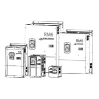
VARIABLE FREQUENCY DRIVE
Brand:
Rhymebus
| Category:
DC Drives
| Size: 5 MB
Table of Contents
Safety Precaution
4
Installation
4
Wiring
5
Operation
6
Main Circuit Terminal Wiring
8
Introductions
10
Features
10
Table of Contents
11
Product Verification
13
Confirmation of Appearance
13
HP (Horse Power) Table for Drive Horse Power Code Conversion
13
Chapter 1 Cautions before Installation
13
Confirmation of Accessories
14
Standard Specifications
14
Single-Phase 200V Series
14
Common Specifications
18
The Features of Control and Operation
18
Basic Equipment
21
Installing the Drive
21
Chapter 2 Installation and Confirmation
21
Internal Cooling
22
External Cooling
23
Drive Mounting Inside the Cabinet/Control Panel
23
Specifications of Associated Accessories
24
Cleaning of Environment
24
Descriptions of Terminal and Wiring Diagram
25
JP5: SINK / SOURCE Selection
25
SINK / SOURCE Definition
30
Using a PLC Circuit
30
Jumper at 1,2 Position; SINK Mode
30
Description of Terminals
31
Main Circuit Terminals
31
Main Circuit Connection
32
Voltage Selection Board of Cooling Fan
35
Control Terminals
35
Control Board
37
Wiring Cautions and Specifications
39
Recommend Wire Size and Molded Case Circuit Breaker
40
Single-Phase 100V Series
40
Wiring Diagram and Setting for Single-Pump and Multi-Pump Applications
42
Single Pump Control(F_015=1)
42
Multi-Pump Control(F_015=2,3,4)
42
Indicators of Keypad
43
Chapter 3 The Setting of Keypad
43
Functions of Keypad (KP-207)
43
Keys of Keypad
44
The Operation of Keypad(KP-207) and Monitor Mode
45
Error Message Display
45
Description of Monitor Mode
46
The Significance of Seven-Segment Displays
47
Description of Function Setting Mode
48
Description of Parameter Setting Mode
48
Operation at Monitor Mode
48
Start / Stop Operation of Drive
49
Parameter Copy
49
Restore Default Value
50
Chapter 4 Parameter List
52
Operation Procedures and Fault Protection
63
Chapter 5 Parameter Setting Description
63
Related Settings of Feedback Signal (Pressure Transmitter) and Pump (Default: Iin Analog Input Terminal)
63
Feedback Signal (Pressure Transmitter)
63
Sequential Control for Multi-Pump
65
Sequential Operation and Parallel Control of Multi-Pump
65
Parallel Control for Multi-Pump
66
Multi-Function Input / Output Terminals
69
Constant Pressure Control Mode
71
Constant Pressure Control Mode and on / off Mode
71
ON / off Control Mode
72
PID Control Functions
73
The Block Diagram of Setting Value and Feedback Value
74
The Block Diagram of PID Control
74
Over-Tuning Suppression
75
Advance Stabilizing
75
Reducing the Oscillation in the Short Period
75
Reducing the Oscillation of Continuous Period
75
Pump Protection
76
Cavitation Phenomenon
77
Dry Running
77
Noise Prevention
78
Water Pipe and System Protection – over Pressure
79
Error Trip Disposals
80
Overheating Disposals
81
Other Functions
82
Chapter 6 Operation Procedures and Fault Protection
85
Operation Procedures
85
Drive Selection
86
Parameter Settings
86
Fault Protection Display and Troubleshooting
87
Error Trip Messages of Drive
87
Warning Messages of Drive
90
Error Trip Messages of Drive at Constant Pressure Control
90
Peripheral Equipment of Drive
92
Selection of Motor
93
Standard Motor
93
Insulation Measurement of Drive and Motor
94
Measure the Drive Insulation Impedance
94
Measure the Motor Insulation Impedance
94
Drive Insulation Impedance Measurement
94
Connection Diagram between Autotransformer and Drive
95
Appendix C Instruction of Drive Charging
95
Braking Transistor Is Installed in the Following Models
96
Aluminum Case Resistor
96
Rated Specification of Braking Resistor
96
Appendix D Dynamic Brake Unit and Braking Resistor
96
Recommending Specification of Braking Resistor
97
Wiring Diagram of External Braking Resistor and Thermal Switch
99
Appendix E Selection of Reactor
103
AC Reactor (ACL) Specifications
104
DC Reactor (DCL) Specifications
105
Outline Dimensions of AC Reactor (ACL)
106
Outline Dimensions of DC Reactor (DCL)
107
Specifications of DC Reactor (DCL)
107
Specification of Product
108
Wiring for RFI
108
Appendix F Selection of Zero-Phase Radio Frequency Filter
108
Outline Dimensions of RFI-01
110
Outline Dimensions of RFI-02
110
Outline Dimensions of RFI-03
111
Outline Dimensions of RFI-04
111
Recommending Specification of EMI Filter
112
Dimension of Internal Panel Type
113
Dimension of External Panel Type
113
Appendix H Instruction of Remote Controller and External Display
113
Internal Cooling Type
115
External Cooling Type
115
Appendix I Outline Dimension Drawing of Drives
115
Attachment 1 Dimension of Keypad (KP-207)
119
Attachment 2 Default Value List
120
Attachment 3 Setting Memo
126
Error Trip Messages of Drive for Constant Pressure Control
129
Attachment 4 Fault Display
129
Advertisement
Advertisement
Related Products
Rhymebus RM6-2001/2-1PH-9426
Rhymebus RM6-2001-1PH-9426
Rhymebus RM6-2001-9426
Rhymebus RM6-2003-9426
Rhymebus RM6-2005-9426
Rhymebus RM6-2010-9426
Rhymebus RM6-2007-9426
Rhymebus RM6-2015-9426
Rhymebus RM6-2002-1PH-9426
Rhymebus RM6-2001/2-9426
Rhymebus Categories
DC Drives
Controller
Water Pump
More Rhymebus Manuals
Login
Sign In
OR
Sign in with Facebook
Sign in with Google
Upload manual
Upload from disk
Upload from URL