Advertisement
Quick Links
Advertisement

Related Manuals for Rhymebus RM6S2 Series


Summary of Contents for Rhymebus RM6S2 Series
- Page 1 AC MOTOR DRIVE Parameter Manual RM6S2/S3 series 2020.05.13 Revised...
-
Page 2: Safety Precaution
Thank you for using RHYMEBUS RM6S2/S3 series drive. For proper operations and safety purposes, please do read and follow specific instructions contained in this manual before using the product. Safety Precaution DANGER 1. Do Not conduct any wiring during the system power ON to avoid the electric shock. -
Page 3: Standard Specifications
Standard Specifications Single phase 200V Series Model 20P5 2001 2002 (RM6S2-□□□□E1) Maximum applicable motor 0.5/0.4 1/0.75 2/1.5 (HP / kW) Rated output capacity (kVA) 1.14 1.71 2.67 Rated output current (A) Three phase 200~240V Maximum output voltage (V) (corresponding input voltage) Range of output frequency 0.1~600.00Hz (Hz) - Page 4 Descriptions of Main Circuit Terminals Type Symbol Function Description Single-phase; sinusoidal power source input AC power R/L1,S/L2 Power terminal. source input Source Three-phase; sinusoidal power source input R/L1,S/L2,T terminals terminal. Drive outputs to Output three-phase variable frequency and Motor U,V,W motor terminals voltage to motor.
-
Page 5: Terminal Wiring Diagram
Terminal Wiring Diagram KP-601A/ Multi-function input PWR/ JPK1 ternimals Modbus FAULT Port Multi-function output terminal RM6S2/S3 (Relay type) AC250V、0.5A,COSθ=0.3 1KΩ Analog input DC 0~10V DC 4~20mA R/L1 Power source S/L2 Motor Description of Indicator Light User can monitor the condition of drive by LED light without the keypad. Condition Fault LED Light(Red) Power/Run LED Light (Green) -
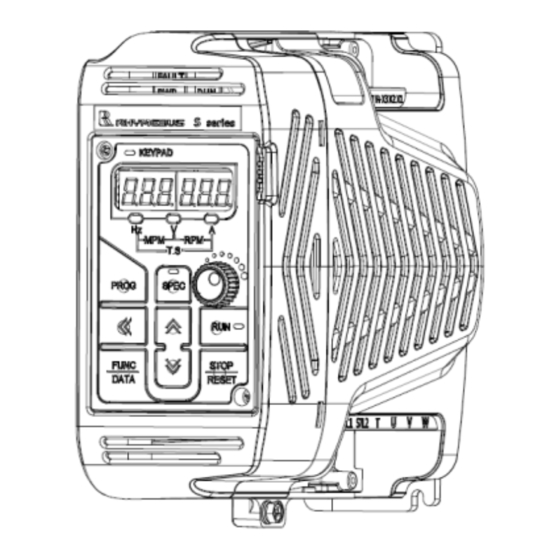
Page 6: Operation Of Keypad
Digital Type Keypad KP-601A (Optional) Display panel 1. ON: Primary frequency command is set by Unit indicator keypad or UP/DOWN terminal Pot knob 2. OFF: Primary frequency command is set by Blinking: Under acceleration multi-function input or deceleration terminals ON: Constant speed OFF: Stop 1. -
Page 7: Parameter List
Parameter List Function Group Name Initialization (4000H) System Keypad Selection (4040H) Function Selection (4065H) Parameters Maintenance Selection (4080H) Operation Mode Selection (4100H) DC Braking (4120H) Application Speed trace (4130H) Multi-Function Component (4140H) Parameters PID Control (4160H) Holding Function (41A0H) Acceleration and Deceleration Times (4200H) S-Curve Characteristics (4220H) V/F Control Compensation (4240H) - Page 8 A System Parameters All Modes A1 Initialization (4000H) Func. Name Description Range Unit Default 0:V/F Control Control Method 2:Sensorless Vector Control ─ A1-02 Selection 6:PM Sensorless Control 1 (I/F+EMF) 7:PM Sensorless Control 2 (HFI+EMF) 0:Disable Auto tuning 1:Rotational auto tuning ─...
- Page 9 Func. Name Description Range Unit Default Gain 1 of main 0.01~ ─ A3-11 1.00 display value Display value = (A3-06) × (A3-11) × (A3-12) 100.00 Gain 2 of main 0.1~ ─ A3-12 display value 1000.0 Main Display The max digits of decimal value on Main ─...
-
Page 10: Application Parameters
b Application Parameters b1 Operation Mode Selection (4100H) Func. Name Description Range Unit Default All Modes Primary 0: Keypad ─ Frequency b1-00 0~10 1: Digital Input terminal (X1~X6) Selection 2: Analog input terminal (AI) 3: Communication interface 7: Machine speed 0 (range:0~65000) Secondary 8: Machine speed 1 (range:0~6500.0) ─... - Page 11 b2 DC Braking (4120H) Func. Name Description Range Unit Default DC Braking All Modes b2-00 Frequency at 0.1~60.0 Active frequency level of DC braking at stop. Stop 0~150 % All Modes of drive DC Braking b2-01 Level rated Set the current level of DC braking. current DC Braking 0.001~...
- Page 12 All Modes b4 Multi-Function Component (4140H) Func. Name Description Range Unit Default Counter Mode 0: Up counter mode ─ b4-00 1: Down counter mode Counter Value ─ b4-01 Set the couter value 1 0~60000 Counter Value ─ b4-02 Set the couter value 2 0~60000 Counter Cycle ─...
- Page 13 Func. Name Description Range Unit Default 0: None PID Feedback 1: Alarm ─ b5-23 loss Detection 2: Ramp to stop Selection 3: Coast to stop PID Feedback -320.00~ ─ b5-24 Low Detection Set the level for PID feedback low detecion. 320.00 320.00 Level...
- Page 14 C Frequency Parameters (4200H) Acceleration and Deceleration Times Func. Name Description Range Unit Default Reference 50.00 All Modes Frequency of 0.01~ C1-00 The frequency corresponding to Accel. / Accel. / Decel. 600.00 60.00 Decel. time. Time All Modes Acceleration 0.0~ C1-01 3200.0 Time 0...
- Page 15 All Modes C2 S-Curve Characteristics (4220H) Func. Name Description Range Unit Default S-Curve 0.00~ C2-00 Characteristics Set S-Curve Characteristics at Accel Start. 0.00 10.00 at Accel Start S-Curve 0.00~ Characteristics Set S-Curve Characteristics at Accel End C2-01 0.00 10.00 at Accel End S-Curve 0.00~ C2-02...
- Page 16 Func. Name Description Range Unit Default Motor 2 Current Oscillation 0.0~ ─ Adjust the output voltage according to the C3-14 Compensation 500.0 current oscillation comensation for motor 2. Gain (0.0:off) Motor 2 Current Oscillation C3-15 0~1.000 0.010 Set the response time of current oscillation Compensation compensation for motor 2.
- Page 17 Func. Name Description Range Unit Default Speed Estimator ─ C5-09 0.00~10.0 0.50 Proportional Adjust the propotional gain of speed Gain estimator. Speed ─ C5-10 Estimator 0.0~200.0 25.0 Integral Gain Adjust the intergral gain of speed estimator. Proportional ─ C5-11 Gain 2 For High 0.1~5 Adjust the propotional gain in high speed.
- Page 18 d Reference Setting All Modes d1 Preset Speed (4300H) Description Multi-speed Multi-speed Multi-speed Multi-speed Func. Name Range Unit Default level 4 level 3 level 2 level 1 command command command command d1-00 Preset Speed 0 60.00 d1-01 Preset Speed 1 10.00 d1-02 Preset Speed 2...
- Page 19 Func. Name Description Range Unit Default UP/DOWN 0.00~ Frequency Adjust UP/DOWN frequency by keypad. d4-03 0.00 600.00 Adjustment Frequency Resolution Set the frequency resolution of UP/DOWN 0.01~ during frequency command during continuous d4-04 4.00 25.00 Continuous Accel./Decel. Accel./Decel. d5 Torque Control (4380H) Func.
-
Page 20: E Motor Parameters
E Motor Parameters E1 Motor 1 V/F Pattern (4400H) Func. Name Description Range Unit Default Maximum 50.0 All Modes E1-00 Output 0.1~600.0 60.0 Set the maximum output frequency of drive. Frequency 0.0~255.0 220.0 Maximum All Modes E1-01 Output Voltage Set the maximum output voltage of drive. 0.0~510.0 380.0 All Modes... - Page 21 Func. Name Description Range Unit Default Motor Iron-Core Sets the motor iron saturation coefficient at ─ E2-08 0.01~1.00 Saturation 75% of magnetic flux. Coefficient 2 Motor Iron-Core Sets the motor iron saturation coefficient at ─ E2-09 0.01~1.00 Saturation 130% of magnetic flux. Coefficient 3 PM Motor Set the value according to the motor...
- Page 22 All Modes E4 Motor 2 parameter (4460H) Func. Name Description Range Unit Default 10%~150% of Motor Rated Set the value according to the motor rated ─ E4-01 drive rated Current current. current Motor Rated Set the value according to the motor rated ─...
- Page 23 G Pump Setting G2 Pump Control Parameter (4830H) Func. Name Description Range Unit Default Pressure Boost Boost the pressure up to detect if the water is ─ G2-00 (Water Usage 0.000~1.000 0.015 used. Detection) Pressure Boost Set the time of G2-00 (Pressure Boost for Time G2-01 Water Usage Detection) to detect if the water...
- Page 24 H Terminal Function All Modes H1 Multi-Function Digital Input (4A00H) Func. Name Description Range Unit Default Multi-function H1-00 Input Terminal (X1) Multi-function H1-01 Input Terminal Parameters of multi-function digital input. (X2) Shown as below. Multi-function (1)If one terminal is set 2 or 3, others terminal H1-02 Input Terminal can’t be set 4 or 6.
- Page 25 All Modes H2 Multi-Function Digital Output (4A20H) Func. Name Description Range Unit Default Multi-function digital output Parameters of multi-function digital output ─ H2-00 -47 ~ +47 terminal shown as below. (Ta1,Tb1) Multi-function Output Selections 0: Disable ±25: PID feedback low detection ±1: Detection during operation ±26: PID feedback high detection ±2: Constant speed detection...
- Page 26 All Modes H3 Multi-Function Analog Input (4A40H) Func. Name Description Range Unit Default Analog Input ─ H3-01 Parameter selection (AI) shown as below. 0~19 Selection (AI) -10.000~ ─ H3-02 The gain ratio of analog input terminal AI. 1.000 Gain (AI) 10.000 -10.000~ ─...
-
Page 27: L Protection Functions
L Protection Functions All Modes L1 Drive & Motor Protection (4C00H) Func. Name Description Range Unit Default 0: Disable Motor Overload 1: Overload protection for dependent cooling ─ L1-02 Protection fan type motor: Enabled (OL) (OL) 2: Overload protection for independent cooling fan type motor: Enabled (OL) Motor overload (150% motor rated current) Motor Overload... - Page 28 All Modes L2 Restart After Instant Power Failure (4C20H) Func. Name Description Range Unit Default 0:Drive cannot be resatrted 1:Drive can be restarted 2:Ramp to stop Operation 3:Restart if the power restore during ramp to Selection at stop. ─ L2-00 Instant Power 4:Ramp to stop with KEB (Enable when start Failure...
- Page 29 L3 Stall Prevention (4C40H) Func. Name Description Range Unit Default Stall Prevention If stall is occurred during acceleration, the L3-00 Level at motor keeps running at constant speed. 30~200 Acceleration (200%: off) Stall Prevention If stall is occurred during constant speed, Level at L3-01 reduce the speed of motor .
- Page 30 Func. Name Description Range Unit Default 0:Disable 1:Detect OL3 during constant speed.(Alarm) 2:Detect OL3 during run. (Alarm) Toreque 3:Detect OL3 during constant speed. (Fault) ─ L4-10 Detection 4:Detect OL3 during run. (Fault) Selection 1 5:Detect UL3 during constant speed.(Alarm) 6:Detect UL3 during run. (Alarm) 7:Detect UL3 during constant speed.
- Page 31 Func. Name Description Range Unit Default Analog Input Detection 2 Set the level of Analog input detection 2: fault 0.000~ ─ L6-04 0.000 Fault Level level detection(H2-□□=31) 1.000 (A2 Err) Analog Input Detection 2 Set the level of Analog input detection 2: warn 0.000~ ─...
- Page 32 P Program Control All Modes P1 Sequence Control (5000H) Func. Name Description Range Unit Default Sequence Control 0:Direct Change ─ P1-00 Change Mode 1:Stop before Change Sequence Control 0:Single direction ─ P1-01 Two-Way Mode 1:Dual direction The cycle times of the sequence control Sequence Control ─...
- Page 33 Func. Name Description Range Unit Default Hold Time of P1-32 Set the hold time of sector 13. 0.0~360.0 Sector 13 Accel/Decel Time P1-33 Set the Accel/Decel time of sector 14. 0.0~360.0 of Sector 14 Hold Time of P1-34 Set the hold time of sector 14. 0.0~360.0 Sector 14 Accel/Decel Time...
- Page 34 o Current Control o1 Current Loop Gain Setting (5900H) Func. Name Description Range Unit Default Gain Adjust the gain of the D-Axis current 0.01~10.0 ─ o1-00 (D-Axis Current) controller. Gain Adjust the gain of the Q-Axis current 0.01~10.0 ─ o1-01 (Q-Axis Current) controller.
- Page 35 U Monitor Parameter U1 Operation Status Monitor (6000H) Func. Name Description Unit 0:V/F Control 2:Open Loop Vector Control ─ U1-00 Control Method 6:PM Open Loop Control 1 7:PM Open Loop Control 2 Frequency U1-01 Display the frequency command 0.01Hz Command U1-02 Output Frequency Display the output frequency 0.01Hz...
- Page 36 U2 Fault Trace (6100H) Func. Name Description Unit Display the fault history item set by ─ U2-00 Fault Histroy Item A5-00 ─ U2-01 Error Code Display the error code of U2-00. Display the frequency command of U2-02 Frequency command 0.01Hz U2-00.
- Page 37 U4 Maintenance Monitor (6300H) Func. Name Description Unit Cumulative Power On U4-00 Display the cumulative power on time. 1 HR Time Cumulative Operation U4-01 Display the cumulative operation time. 1 HR Time Cooling Fan Operation Display the cumulative operation time of the U4-02 1 HR Time...
- Page 38 U5 PID Monitor (6400H) Func. Name Description Unit U5-01 PID Setpoint Display the PID setpoint. U5-02 PID Feedback Display the feedback of PID control. PID Differential U5-03 Display the PID differential feedback. Feedback Display the PID adjusted feedback. If differential feedback isn’t used, the value U5-04 PID Adjusted Feedback will be same with U5-02.
- Page 39 PM Control Items Func. Name Description Range Unit Default Control Method 6:PM Sensorless Control 1 (I/F+EMF) ─ A1-02 Selection 7:PM Sensorless Control 2 (HFI+EMF) Auto tuning ─ A1-03 4:PM stationary Auto tuning Function ─ ─ ─ A1-05 Default Setting dFPM:Restore the default value of PM control ASR Proportional Adjust the ASR proportional gain in high ─...
- Page 40 Error Trip Messages of Drive Display Description Display Description (EEr) (PAdF) KEYPAD KEYPAD Keypad connection EEPROM Error interrupted (EEr0) (OH0) KEYPAD KEYPAD EEPROM Error 0 Drive overheat (AdEr) (OH2) KEYPAD KEYPAD A/D converter error Motor overheat (SC) (A1ERR) KEYPAD KEYPAD Fuse open Analog input protection 1 (LE1)
- Page 41 Error Trip Messages of Drive Display Description Display Description (OLO) (OL4) KEYPAD KEYPAD Motor over torque 2 System overload (UL3) (UL4) KEYPAD KEYPAD Motor under torque 1 Motor under torque 2 (oS) (dEV) KEYPAD KEYPAD Over speed Speed deviation Warning Messages of Drive Display Description Display...
- Page 42 Outline Dimension (1)Outline Dimension of Drive (Exclude KP and KP Accessory) Ø 4.5 165.5 Unit:mm (2) Outline Dimension (Include KP and KP Accessory) Ø 4.5 165.5 Unit:mm...
Need help?
Do you have a question about the RM6S2 Series and is the answer not in the manual?
Questions and answers
What does LE1fault code mean
The LE1 fault code for the Rhymebus RM6S2 Series indicates a power source under voltage trip.
This answer is automatically generated