Advertisement
Quick Links
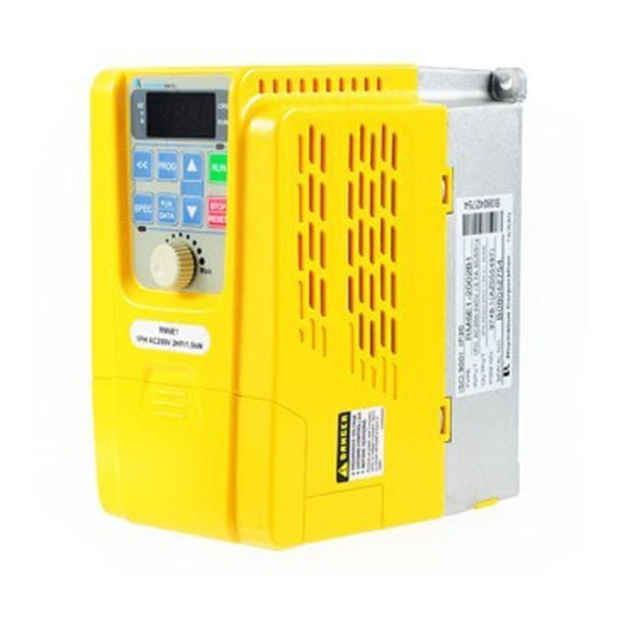
RM6E1 Series
Simple Version
Operation Manual
Thank you for using RHYMEBUS RM6E1 series drive.
For proper operations and safety purposes, please read complete manual carefully (enclose
CD inside the box) or visit RHYMEBUS website:
the operation manual. To prevent any possible dangers ,only the qualified personnel may
proceed with the installation. Please pay attention to the safety precautions marked with
"DANGER" or "CAUTION" in complete manual before installation.
DANGER
CAUTION
※Although the "
incurred if the caution is not under user's attention.
Terminals of Main Circuit
Type
Symbol
Power
R/L1,S/L2,T/L3
Source
Motor
U/T1,VT2,W/T3
P⊕,NΘ
Power
and Brake
P⊕,PR
Grounding
User may cause the casualty or serious damages if user does not abide by the
instructions of the manual to execute the tasks.
User may cause injuries to the people or damage the equipment if user does not
abide by the instructions of the manual to execute the tasks.
" mark may indicate minor damages, serious damages or injuries may be possibly
Function
AC power source input
terminals
Drive outputs to motor
terminals
Dynamic braking unit
connecting terminal
External braking resistor
connectingterminal
Grounding terminal
http://www.rhymebus.com.tw
http://www.rhymebus.com.tw
Three-phase; sinusoidal power source input
terminal. For the single-phase power source
110/220V, please connect only R/L1,S/L2
terminals.
The terminals output three phase variable
frequency and voltage to motor.
The terminals between P⊕and NΘ connect
dynamic braking unit (option).
The terminals between P⊕and PR connect
external braking resistor (option).
Ground the drive in compliance with the NEC
standard or local electrical code.
1
2020.08.28 Edition
XB200161
to download
Description
Advertisement

Related Manuals for Rhymebus RM6E1 Series


Summary of Contents for Rhymebus RM6E1 Series
- Page 1 RM6E1 Series Simple Version Operation Manual http://www.rhymebus.com.tw 2020.08.28 Edition Thank you for using RHYMEBUS RM6E1 series drive. XB200161 For proper operations and safety purposes, please read complete manual carefully (enclose CD inside the box) or visit RHYMEBUS website: http://www.rhymebus.com.tw to download the operation manual.
-
Page 2: Descriptions Of Terminal And Wiring Diagram
Descriptions of Terminal and Wiring Diagram Braking Resistor (option) Three-phase, Induction Motor R/L1 R/L1 U/T1 50/60Hz RM6E1 AC power input: S/L2 S/L2 V/T2 (Single Phase-Only T/L3 W/T3 T/L3 R/L1, S/L2 Terminals) SINK SOURCE Multi-function Input 1 Multi-function Input 2 Analog Output Multi-function Input 3 DC0~10V(0~20mA) - Page 3 Symbol Function Description Type Multi-function input Short the terminal of X5 with COM and set the function F5.23. terminal 5 (default: disable) Multi-function input Short the terminal of X6 with COM and set the function F5.24. terminal 6 (default: disable) Input/output The common terminal of input control signal.
- Page 4 Parameter List [ F1 Operation Parameter ] Range of Func. Name Descriptions Unit Default Setting Start command Rotation direction FWD or REV command FWD or REV command FWD command REV command FWD, REV command Forward Operation panel Start Command Reverse ─...
- Page 5 Range of Func. Name Descriptions Unit Default Setting Number of Motor F1.12 Determination of RPM display value. 2~10 Poles Machine Speed Set the ratio of machine speed. This function determines F1.13 0.00~500.00 0.01 20.00 Ratio MPM display value. Digits of Decimal Select the digits of decimal values displaying the machine ─...
- Page 6 Range of Func. Name Descriptions Unit Default Setting Primary The deceleration time of primary speed, preset speed 0.0~ F2.19 DecelerationTime 5~16, and jog speed. 3200.0 F2.20 Acceleration Time 0.0~ Acceleration time of preset speed 2 of Preset Speed 2 3200.0 Deceleration Time 0.0~ F2.21...
- Page 7 Parameter List [ F3 Control Parameter ] Range of Func. Name Descriptions Unit Default Setting The drive accelerate to the holding frequency and Holding Frequency 0.0~400.00 0.1Hz F3.00 running at constant speed. The drive runs at holding frequency by constant F3.01 Holding Time Interval 0.0~360.0 0.1sec...
- Page 8 Range of Func. Name Descriptions Unit Default Setting 75.0~96.0 87.5 *Note 3 *Note 3 The Voltage Level Set the voltage level of power source for ramp to 150.0~192.0 175.0 F3.31 Setting at Power stop. When the voltage of power input is lower than 0.1V *Note 4 *Note 4...
- Page 9 Range of Func. Name Descriptions Unit Default Setting Drive Overheat Set the temperature level of warning alarm. 45~105 1℃ F4.14 Pre-alarm Level Drive Overheat Dead Set the temperature dead band of temperature F4.15 0.1~10.0 0.1℃ Band warning and fan active level. 0: Forced air: Start the fan at power on.
- Page 10 Range of Func. Name Descriptions Unit Default Setting 0: Disable PID Feedback High ─ F4.45 1: Warning, drive continuous operation. Detection Setting 2: Error, drive trip to stop. PID Feedback High F4.46 Detect if the PID feedbackis higher than setting level 0~100 Detection Level F4.47 PID Feedback High...
- Page 11 Range of Func. Name Descriptions Unit Default Setting 0:DC 4~20mA (2~10V) FM Range ─ F5.15 0, 1 Option 1:DC 0~20 mA (0~10V) 0: Disable ±16: Clean UP/DOWN Multi-function ±1: Jog command frequency command -31 ~ +31 ─ F5.19 Input Terminal ±2: Secondary accel / decel ±17: UP/DOWN command *Note 7...
- Page 12 Range of Func. Name Descriptions Unit Default Setting 1~5: Terminal adjust the response time. Continuous UP/DOWN acceleration or deceleration when over the ─ F5.32 Calibrating Time setting time 6: Edge trigger UP/DOWN Frequency Adjust UP/DOWN frequency on keypad directly 0.00~400.00 0.01Hz 0.00 F5.33 Adjustment 0: Up counting mode...
- Page 13 Range of Func. Name Descriptions Unit Default Setting Accel/Decel Time of Sector 4 Set the accel/decel time of sector 4 of sequential F6.11 0.0~360.0 0.1sec of Sequential operation control. Operation Control Hold Time of Sector 4 Set the hold time of sector 4 of sequential operation F6.12 0.0~360.0 0.1sec...
- Page 14 Range of Func. Name Descriptions Unit Default Setting Accel/Decel Time of Sector 12 of Set the accel/decel time of sector 12 of sequential F6.27 0.0~360.0 0.1sec Sequential operation control. Operation Control Hold Time of Sector 12 Set the hold time of sector 12 of sequential operation F6.28 0.0~360.0 0.1sec...
- Page 15 Range of Func. Name Descriptions Unit Default Setting -100~100%of Integration Lower F6.48 Set the lower limitation value of integrator. maximum Limitation frequency -100~100% Integrator Set the initial value of the integrator before PID of maximum F6.49 Initialized Value starts. frequency PID Output Upper Set the PID control output frequency 0.00~1.00...
- Page 16 Fault Displays Error Trip Messages of Drive Display Description Display Description noFb IGBT module error PID feedback signal error AdEr Grounding fault A/D converter error Drive over current External fault PAdF Keypad interruption Motor overload during copy Drive overload EEPROM error EEr1 Drive current limit...
Need help?
Do you have a question about the RM6E1 Series and is the answer not in the manual?
Questions and answers