Advertisement
Quick Links
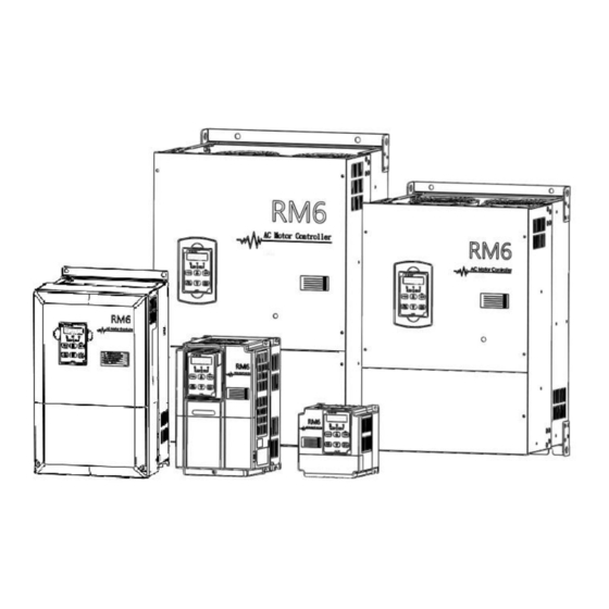
RM6 Series
Simple Version
Operation Manual
Thank you for using RHYMEBUS RM6 series drive.
For proper operations and safety purposes, please read manual carefully .
Only the qualified personnel may proceed with the installation.
Visit RHYMEBUS website:
Please pay attention to the safety precautions marked with "DANGER" or "CAUTION" in
complete manual before installation.
DANGER
CAUTION
Terminals of Main Circuit
R,S
(L,N)
R,S,T
(L1,L2,L3)
○ +
○ -
, N
U,V,W
(T1,T2,T3)
P(+), N○ -
Dynamic brake unit
P○ + , N○ -
P, N
P, PR
P(+), PR
P○ + , PR
P(+), P1
P○ + , P1
PE(or G)
Grounding terminal Ground the drive in compliance with the NEC standard
http://www.rhymebus.com.tw
User may cause the casualty or serious damages if user does not abide
by the instructions of the manual to execute the tasks.
User may cause injuries to the people or damage the equipment if user
does not abide by the instructions of the manual to execute the tasks.
AC power source
input terminals
DC power source
input terminals
Drive outputs to
motor terminals
terminal
External
brakingresistor
terminal
External reactor
terminal
http://www.rhymebus.com.tw
Single-phase; sinusoidal power source input terminals.
Three-phase; sinusoidal power source input terminals.
External DC power source terminal.
※Only 2007 ~ 2015, 4007 ~ 4020 models have the terminal.
Output three-phase variable frequency and voltage to
motor.
The terminals can connect to dynamic braking
unit(option).
The terminals can connect to external brake resistor
(option).
The terminal can connect to DC reactor (DCL) for
improving power factor. The default setting is
connected by a jumper.
or local electrical code.
1
2020.02.06 Edition
for complete operation manual.
Advertisement

Related Manuals for Rhymebus RM6 Series


Summary of Contents for Rhymebus RM6 Series
- Page 1 RM6 Series Simple Version Operation Manual http://www.rhymebus.com.tw 2020.02.06 Edition Thank you for using RHYMEBUS RM6 series drive. For proper operations and safety purposes, please read manual carefully . Only the qualified personnel may proceed with the installation. Visit RHYMEBUS website: http://www.rhymebus.com.tw for complete operation manual.
- Page 2 Decription of terminal and wiring diagram Model:RM6-1001/2-1PH~RM6-1002-1PH ; RM6-2001/2-1PH~RM6-2002-1PH Model:RM6-2001/2~RM6-2005 ; RM6-4001~RM6-4005 ※2: Braking Resistor(option) Induction Motor ※Single-Phase connect to R/L1 R/L1 U/T1 R/L1,S/L2 terminal. S/L2 S/L2 ※Three-Phase connect to V/T2 T/L3 T/L3 R/L1,S/L2 ,T/L3 terminal. W/T3 Model:RM6-2007 ~ RM6-2015; Model:RM6-4007 ~ RM6-4025;...
- Page 3 Model: RM6-2050 ~ RM6-2075; Model: RM6-4075 ※1:DC reactor(DCL; option) Jumper Induction Motor P(+) R/L1 R/L1 U/T1 Three-Phase, S/L2 S/L2 50/60Hz AC Power Input V/T2 T/L3 T/L3 W/T3 Model(B Type): RM6-2050B ~ RM6-2075B; Model(B Type): RM6-4075B ~ RM6-4175B ※2: Braking Resistor(option) Induction Motor R/L1 R/L1...
- Page 4 Multi-function output ․Capacity: DC48V, 50mA Max terminals (open collector type) Common terminal of Y1, Y2. Signal transmission ․Connect the RM6 series drive by transmission cable, terminal(+) when the drive is controlled by RS-485 communication interface. Signal transmission ․Communication protocol: Modbus...
- Page 5 Description of Terminal and Wiring Diagram Forward Analog Output Terminal Reverse (DC 0~10V) Multi-function Input Terminal 1 (GND) Multi-function Input Terminal 2 ※1 Multi-function Input Terminal 3 SINK Multi-function Input Terminal 4 Multi-function Output Terminal Multi-function Input Terminal 5 (Relay Type) Multi-function Input Terminal 6 SOURCE...
-
Page 6: Operation Of Keypad
Digital Type Keypad (KP-603) for RM6 Display panel 1. ON: Primary frequency command is set by Unit indicator keypad or UP/DOWN terminal Pot knob 2. OFF: Primary frequency command is set by Blinking: Under acceleration multi-function input or deceleration terminals ON: Constant speed OFF: Stop... - Page 7 Description of Monitor Mode There are eight displays can be selected in the monitor mode. Press to switch the DATA display in accordance with below sequence under monitor mode. User can determine one of eight displays as the main display from function F_006 (Selection of Main Display). Please refer to the following illustrations: Display 1 Display 2...
- Page 8 Range of Func. Name Description Unit Default Setting 0: Frequency command by analog signal via terminal. 1: Frequency command by keypad. Primary 2: Motor speed (RPM) command by keypad. Frequency 3: Machine speed (MPM) command by keypad. ─ F_002 Command 4: Frequency command by UP/DOWN terminal.
- Page 9 Range of Func. Name Description Unit Default Setting F_026 Deceleration Time Deceleration time of preset speed 3. of Preset Speed 3 Secondary Switch to secondary acceleration time by 0.0~ 15.0 F_027 Acceleration Time multi-function input terminal. 3200.0 (Note5) Secondary Switch to secondary deceleration time by F_028 Deceleration Time multi-function input terminal.
- Page 10 Range of Func. Name Description Unit Default Setting Motor Slip According to the load condition, set the compensation -9.9~10.0 0.1Hz F_050 Compensation for motor running at constant speed. (0.0: off) Number of Motor Determinate the RPM display value of monitor mode. 2~10 F_051 Poles...
- Page 11 Range of Func. Name Description Unit Default Setting System Overload 0: Disable ─ F_065 Detection (OLO) 1: Enable System Overload 0: Detection during constant speedonly ─ F_066 Detecting Selection 1: Detection during operation only 0: Drive keeps operation when “OLO” is detected Output Setting after ─...
- Page 12 Range of Func. Name Description Unit Default Setting F_089 Delay Time before Set the delay time before the speed tracing and 0.1~5.0 0.1sec Speed Tracing coast stop+ DC braking. The V/F Pattern of Set the percentage of V/F output voltage at the speed F_090 0~100% Speed Tracing...
- Page 13 Range of Func. Name Description Unit Default Setting Communication 0: 8,N,2 1: 8,E,1 ─ F_112 Protocol 2: 8,O,1 3: 8,N,1 When the message transmission is interrupted or Communication 0.0~ delays during communication transmission, drive F_113 Overtime (Cot) 100.0 displays “Cot” message. (0.0: disable) 0: Warning (Cot);Continue operation Communication ─...
- Page 14 Range of Func. Name Description Unit Default Setting ─ F_136 PID Error Gain Set the gain for the error of PID. 0.1~8.0 If “stop command” is activation at multi-funtion input Delay Time before F_137 0~1200 1 sec Stop terminal, drive will delay the setting time before stop. F_138 Overheating Level 0.0~25.0 0.1℃...
- Page 15 Range of Func. Name Description Unit Default Setting Feedback Signal 0: Direct proportion signal. ─ F_165 Selection 1: Inverse proportion signal. PI Control) 2nd PI control starts when the deviation value is F_166 0.0~25.0 Active Range within the setting range(SV±F_166) (0.0: Disable) PI Control) control work with the time duration and then F_167...
- Page 16 Range of Func. Name Description Unit Default Setting Feedback Limit Set the physical volume according to the specification -800.0~ F_191 Level of transmitter(refer to F_151, F_152) 800.0 0: Detection when “PV” > F_191 Feedback Limit ─ F_192 1: Detection when “PV” < F_191 Detection Setting Feedback Limit When the feedback signal exceeds the setting value...
-
Page 17: Eeprom Error
Error Trip Messages of Drive Display Description Display Description (EEr) (OLO) KEYPAD KEYPAD EEPROM error System overload (AdEr) (thr) KEYPAD KEYPAD A/D converter error External fault (SC) (PAdF) KEYPAD KEYPAD Keypad interruption Fuse open during copy (LE1) (OH) KEYPAD KEYPAD Under voltage Drive overheating during operation... - Page 18 Warning Messages of Drive Display Description Display Description (LE) (Err_00) KEYPAD KEYPAD Power source Err_00: Keypad cable under voltage trip.(before connecting) (bb) (Err_01) KEYPAD KEYPAD Drive output Err_01: Keypad cable interruption trip.(connected) (Fr) (Wr_F) KEYPAD Different software KEYPAD Coast to stop version inter-copy (PUF1) (db)
Need help?
Do you have a question about the RM6 Series and is the answer not in the manual?
Questions and answers