Table of Contents
Advertisement
Quick Links
Advertisement
Table of Contents
Troubleshooting

Related Manuals for Rhymebus RM6E1 Series


Summary of Contents for Rhymebus RM6E1 Series
- Page 1 VARIABLE FREQUENCY DRIVE Operation Manual RM6E1 series...
- Page 2 Quality․Satisfaction․Improvement․Innovation http://www.rhymebus.com.tw 2015.05.05 Revised...
- Page 3 PREFACE Thank you for using RHYMEBUS RM6E1 series drive. For proper operations and safety purposes, please do read and follow specific instructions contained in this manual before using the product. The manual shall be placed on the top of the machine, and all the setup parameters and reference numbers must be properly recorded in Attachment 1 to facilitate future maintenance and repairs.
- Page 4 SAFETY PRECAUTION Please read this manual thoroughly and pay attention to the safety precautions marked with ― DANGER ‖ or ― CAUTION ‖ before the installation, wiring, maintenance, or troubleshooting. Only the qualified personnel may proceed with the installation, wiring, testing, troubleshooting, or other tasks.
- Page 5 U/T1,V/T2,W/T3 terminal of drive at first. CAUTION a. The RM6E1 series outputs are designed to drive a three-phase induction motor. Do Not use for single-phase motor or using for other purposes. b. The main circuit and control circuit must be wired separately; control circuit must...
- Page 6 Operation DANGER a. Do Not open or remove the cover while power is on or during the drive operation. Do close up the cover before powering on the drive. Do Not remove the cover except for wiring or periodic inspection when power off. b.
- Page 7 INTRODUCTIONS Features a. With the temperature management and fan control functions to increase the lifetime of cooling fan and saving the energy. a. User can monitor the temperature of drive and setting the pre-alarm level to forecast the maintenance cycle of cooling fan. b.
-
Page 8: Table Of Contents
TABLE OF CONTENTS --------------------------- 1 HAPTER AUTIONS EFORE NSTALLATION 1-1 PRODUCT VERIFICATION ----------------------------------------------------------------- 1 1-1-1 Confirmation of Appearance -------------------------------------------------------- 1 1-1-2 The description of nomenclature -------------------------------------------------- 1 1-1-3 Confirmation of Accessories -------------------------------------------------------- 2 1-2 STANDARD SPECIFICATIONS ----------------------------------------------------------- 2 1-2-1 Single-Phase 100V Series ---------------------------------------------------------- 2 1-2-2 Single-Phase 200V Series ---------------------------------------------------------- 3 1-2-3 Three-Phase 200V Series ----------------------------------------------------------- 3 1-2-4 Three-Phase 400V Series ----------------------------------------------------------- 4... - Page 9 3-3-6 The Operation in the Monitor Mode --------------------------------------------- 31 3-3-7 Start/Stop of the Drive -------------------------------------------------------------- 31 3-3-8 Save and Restore the Setting Value. ------------------------------------------- 32 ----------------------------------------------- 34 HAPTER ARAMETER F0 SYSTEM PARAMETERS------------------------------------------------------------------- 35 F1 OPERATION PARAMETERS ------------------------------------------------------------- 36 F2 FREQUENCY PARAMETERS ------------------------------------------------------------ 39 F3 CONTROL PARAMETERS ---------------------------------------------------------------- 42 F4 PROTECTION PARAMETERS ----------------------------------------------------------- 45 F6 SPECIAL PARAMETERS ------------------------------------------------------------------ 52...
- Page 10 PPENDIX HASE ADIO REQUENCY ILTER ELECTION ------------------------------------- 156 PPENDIX ELECTION OF OTOR ----------------------- 158 PPENDIX NSTRUCTION OF RIVE HARGING ------------------------- 159 PPENDIX YNAMIC RAKE AND ESISTOR ------------------------- 163 PPENDIX UTLINE IMENSION RAWINGS ------------------------------------------ 166 TTACHMENT ETTING ----------------------------------------- 171 TTACHMENT AULT ISPLAYS...
- Page 11 No Text on This Page viii...
-
Page 12: Chapter 1 Cautions Before Installation
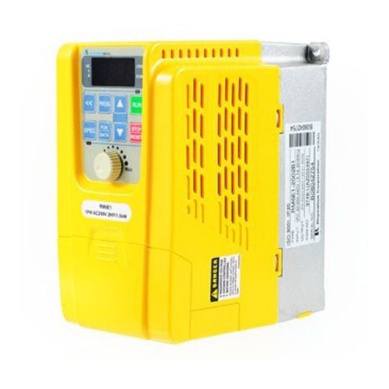
3PH AC200-240V 8A 0.1-400.00Hz Output Current & Capacity PGM NO. 9748-1 Software Number SERIAL NO. XXXXXXX Product Serial Number Rhymebus Corporation, Taiwan 1-1-2 The description of nomenclature — 2 002 B 3 RM6E1 Input Power Phase 1: Single-Phase 3: Three-Phase Brake Type... -
Page 13: Confirmation Of Accessories
Chapter 1 Cautions Before Installation 1-1-3 Confirmation of Accessories One user manual is inclusive. Please verify other accessories inclusively such as braking resistor, AC reactor, etc.. ※Please refer to the standard specifications to verify the product specifications with your requirements. 1-2 Standard Specifications 1-2-1 Single-Phase 100V Series Model name... -
Page 14: Single-Phase 200V Series
Chapter 1 Cautions Before Installation 1-2-2 Single-Phase 200V Series Model name 20P5 2001 2002 2003 □□□□ (RM6E1- Maximum applicable 0.5 / 0.4 1 / 0.75 2 / 1.5 3 / 2.2 motor (HP / kW) Rated output capability (kVA) Rated output current (A) Rated output voltage (V) Three-phase 200~240V Range of output... -
Page 15: Three-Phase 400V Series
Chapter 1 Cautions Before Installation Model name 2003 2004 2005 □□□□ (RM6E1- Maximum applicable 3 / 2.2 4 / 3 5 / 3.7 motor (HP / kW) Rated output capability (kVA) Rated output current (A) Rated output voltage (V) Three-phase 200~240V Range of output 0.1~400.00Hz frequency (Hz) - Page 16 Chapter 1 Cautions Before Installation Model name 4005 4007 □□□□ (RM6E1- Maximum applicable 5 / 3.7 7.5 / 5.5 motor (HP / kW) Rated output capability (kVA) Rated output current (A) Rated output voltage (V) Three-phase 380~480V Range of output 0.1~400.00Hz frequency (Hz) Power source (ψ, V, Hz)
-
Page 17: Common Specifications
Chapter 1 Cautions Before Installation 1-3 Common Specifications 1-3-1 The Features of Control and Operation ․Voltage vector sinusoidal PWM control(V/F control); Control method ․Switching frequency: 800Hz~16kHz Range of 0.1~400.00Hz frequency setting Resolution ․Operation panel: 0.01Hz of frequency ․Analog signal: 0.06Hz / 60Hz setting Resolution of output... - Page 18 Chapter 1 Cautions Before Installation Command the drive via 6 programmable multi-function input terminals(X1~X6): Forward command / Reverse command, Start method 3-wire start/stop control, 16 sets preset speed control. Communication control. 6 programmable input terminals: X1~X6 Multi-function Response time:1~255 ms inputs Refer to the chapter of function setting description for F5.19~F5.24.
-
Page 19: The Disassembled Sketch Of Rm6E1
Chapter 1 Cautions Before Installation Power source under voltage(LE), Drive output interruption(bb), Coast to stop(Fr), Braking transistor is active (db), Keypad cable trip before connecting(Err_00), Keypad Warning cable trip during operation(Err_01), System overload(OLO), messages of Power source under voltage(Hv), Power source under drive voltage(LE), Drive overheat(OHt), Motor overheat(OH1), FWD/REV command input simultaneously(dtF)、Different... - Page 20 Chapter 1 Cautions Before Installation No Text on This Page...
-
Page 21: Chapter 2 Installation And Confirmation
Chapter 2 Installation and Confirmation Chapter 2 Installation and Confirmation 2-1 Basic Equipment The drive needs the several components for the conjunctive operation. These components are called ―basic equipment‖, listed in the following: 2-1-1 Power Source: The voltage with three-phase or single-phase of the power source must meet the drive specifications. - Page 22 Chapter 2 Installation and Confirmation 2-2-3 Arrangement: The fluent air ventilation inside the control panel/cabinet must be considered when a drive is installed inside. Please refer to as below figure 1: Correct Incorrect Outlet Outlet Outlet Outlet RM5G/P RM5G/P Drive Drive Driver Driver...
- Page 23 Chapter 2 Installation and Confirmation 2-2-4 Specifications of Associated Accessories: The specifications of the accessories must be according to the specifications of the drive. Otherwise, the drive will be damaged and the lifetime of the drive will be shorten. Do Not add any power factor leading capacitor(RC, LC or other capacitance component) between the drive and motor to avoid any accidents.
-
Page 24: Descriptions Of Terminal And Wiring Diagram
Chapter 2 Installation and Confirmation 2-3 Descriptions of Terminal and Wiring Diagram 2-3-1 Wiring Diagram Braking Resistor (option) Main Circuit Terminals Control Terminals Induction Motor Three-phase, 50/60Hz R/L1 R/L1 U/T1 AC power input: RM6E1 S/L2 S/L2 V/T2 (Single Phase-Only R/L1, S/L2 Terminals) T/L3 W/T3... -
Page 25: Sink / Source Definition
Chapter 2 Installation and Confirmation 2-3-2 SINK / SOURCE Definition There are two ways of connection for multi-function input terminals: a. JP2: “SINK” position PLC(NPN) RM6E1 Drive RM6E1 Drive X1~X6 X1~X6 SOURCE SOURCE SINK SINK When JP2 is switched to ―SINK‖ position and short-circuit the X1~X6 terminals with COM terminal, drive is activate. -
Page 26: Description Of Terminals
Chapter 2 Installation and Confirmation 2-3-3 Description of Terminals a. Terminals of Main Circuit Type Symbol Function Description Three-phase; sinusoidal power source AC power input terminal. Power R/L1,S/L2,T/L3 source input For the single-phase power source Source terminals 110/220V, please connect only R/L1,S/L2 terminals. - Page 27 Chapter 2 Installation and Confirmation b. Main Circuit Connection i. 100 / 200V single-phase AC power Tightening Screw size Tightening torque Screw size Model no. torque of of main circuit grounding main circuit terminal screw grounding RM6E1- terminal screw terminal Ib-in(kgf-cm) terminal Ib-in(kgf-cm)
- Page 28 Chapter 2 Installation and Confirmation ii. 200 / 400V three-phase AC power Tightening Screw size Tightening torque Screw size Model no. torque of of main circuit grounding main circuit terminal screw grounding RM6E1- terminal screw terminal Ib-in(kgf-cm) terminal Ib-in(kgf-cm) 20P5B3 2001B3 21P5B3 2002B3...
- Page 29 Chapter 2 Installation and Confirmation c. Control Terminals Control Terminal Mapping X3 COM X2 X1 FM GND AI V+ Type Symbol Function Description DC+12V position: Maximum supplied current Power terminal for is 20mA. DC+24V position: Maximum supplied current analog input control *Note 3 is 50mA.
-
Page 30: Wiring Cautions And Specifications
Chapter 2 Installation and Confirmation . KP-601 Keypad / Modbus Port (RJ-45) Type Function Description Communication Differential input of RS-485 transmission terminal (DX+) *Note 1 Communication Modbus (RS-485) communication transmission only uses pin1, 2. terminal (DX-) Modbus(RS-485) Power terminal of Only for KP-601 linking /KP-601 KP-601(+16V) - Page 31 Chapter 2 Installation and Confirmation d.Recommended wire size and Molded Case Circuit Breaker(MCCB) Single-phase 100V series Control Input Output Grounding Model no. Input MCCB circuit wire (R/L1,S/L2,T/L3) (U/T1,V/T2,W/T3) wire size current wire size wire size size RM6E1- (mm²/ AWG) (mm²/AWG) (mm²/AWG) (mm²/AWG) 10P5B1...
- Page 32 Chapter 2 Installation and Confirmation Three-phase 400V series Control Input Output Grounding Model no. Input MCCB circuit wire (R/L1,S/L2,T/L3) (U/T1,V/T2,W/T3) wire size current wire size wire size size RM6E1- (mm²/ AWG) (mm²/AWG) (mm²/AWG) (mm²/AWG) 4001B3 0.5/20 0.5/20 2.1/14 4002B3 0.8/18 0.5/20 2.1/14 0.75~1.25/...
- Page 33 Chapter 2 Installation and Confirmation No Text on This Page...
-
Page 34: Chapter 3 The Setting Of Operation Panel & Remote Controller
Chapter 3 The Setting of Operation Panel & Remote Controller Chapter 3 The Setting of Operation Panel & Remote Controller 3-1 Functions of Operation Panel KP-601/Modbus ▲ << PROG ▼ FUNC STOP SPEC DATA RESET SPEC 3-1-1 Indicators of Operation Panel Symbol Name Description... -
Page 35: Keys Of Operation Panel
Chapter 3 The Setting of Operation Panel & Remote Controller ▲ Shift key Operation key << PROG UP key Program key ▼ Down key Function/Data key FUNC STOP SPEC DATA RESET STOP/RESET key Special function key Pot knob 3-1-2 Keys of Operation Panel Symbol Name Description... -
Page 36: Functions Of Remote Controller(Kp-601 Keypad)
Chapter 3 The Setting of Operation Panel & Remote Controller 3-2 Functions of Remote Controller(KP-601 keypad) KEYPAD SPEC PROG SPEC 《 ︽ ︾ FUNC STOP DATA RESET 3-2-1 Indicators of Keypad Symbol Name Explanation Frequency Indicating the unit of frequency indicator Voltage indicator Indicating the unit of voltage... -
Page 37: Keys Of Keypad
Chapter 3 The Setting of Operation Panel & Remote Controller KEYPAD Special function key Program key PROG SPEC Pot knob UP key 《 ︽ Operation key Shift key Down key ︾ FUNC STOP Function/Data key Stop/Reset key DATA RESET 3-2-2 Keys of Keypad Symbol Name Descriptions... -
Page 38: The Operation Of The Operation Panel And Monitor Mode
Chapter 3 The Setting of Operation Panel & Remote Controller 3-3 The Operation of the Operation Panel and Monitor Mode 3-3-1 The Operation of Operation Panel The operation of the operation panel includes fault messages and three modes. The switching methods are shown as below figure: Monitor mode Function setting mode Parameter setting mode... -
Page 39: Monitor Mode
Chapter 3 The Setting of Operation Panel & Remote Controller 3-3-2 Monitor Mode There are eight monitor modes can be selected in the monitor mode. User can determine one of eight monitor modes as the main display on the operation panel. And the monitor mode can be switched as shown in below figure: Enter monitor mode Display 1... -
Page 40: The Status Of Multi-Function Terminals
Chapter 3 The Setting of Operation Panel & Remote Controller 3-3-3 The Status of Multi-function Terminals The default setting of ―Display 6‖ is the status of multi-function input terminals and the definition of each segment on the seven-segment display for 4 digits is shown as below figure: Ta/Tc The definition of display shown in the below table: Display... -
Page 41: Parameter Setting Mode
Chapter 3 The Setting of Operation Panel & Remote Controller c.The selection of function number: Operation Steps Display 1.Press key to switch to the function number setting << mode after the function group is selected. And the function number is flashing. ▲... -
Page 42: The Operation In The Monitor Mode
Chapter 3 The Setting of Operation Panel & Remote Controller 3-3-6 The Operation in the Monitor Mode Frequency command, motor speed(RPM), machine speed(MPM) are changeable under monitor mode. For example of frequency command change, the setting steps are shown in the following table. The operation steps are shown in the below table: Operation Steps Display... -
Page 43: Save And Restore The Setting Value
Chapter 3 The Setting of Operation Panel & Remote Controller 3-3-8 Save and Restore the Setting Value. a.The operation steps of saving drive function setting are shown in the below table: Operation Steps Display 1.Press key and enter the function setting mode. PROG 2.Press key and switch to the function number setting... - Page 44 Chapter 3 The Setting of Operation Panel & Remote Controller No Text on This Page...
-
Page 45: Chapter 4 Parameter List
Chapter 4 Parameter List Chapter 4 Parameter List Group List Group Function System status Parameter locking System Password protection Parameters Power source voltage setting Fault record Default setting Start command selection Frequency command selection Operation Main display selection Parameters SPEC key setting Switching frequency Stop mode Preset speed... -
Page 46: F0 System Parameters
Chapter 4 Parameter List F0 System Parameters Range of Func. Name Descriptions Unit dF60 Page Setting 0: Software version 1: Drive model number 2: Drive rated current Drive ─ ─ ─ F0.00 Information 3: Drive running hours 4: Drive supply power time 5: Software checksum code Parameter 0: Parameters are changeable... -
Page 47: F1 Operation Parameters
Chapter 4 Parameter List F1 Operation Parameters Range of Func. Name Descriptions Unit dF60 Page Setting Start command Rotation direction FWD or REV FWD or REV command command FWD command REV command FWD, REV command Forward Operation panel Reverse Start Reverse ─... - Page 48 Chapter 4 Parameter List Range of Func. Name Descriptions Unit dF60 Page Setting Validity of 0: Start command from the terminal, STOP of the STOP key disabled. ─ F1.05 0, 1 Operation 1: Start command from the terminal, Panel STOP key enabled. Frequency 0: In the monitor mode, frequency Command...
- Page 49 Chapter 4 Parameter List Range of Func. Name Descriptions Unit dF60 Page Setting SPEC Key -28 ~ +28 ─ F1.17 Same function as multi-function input Setting *Note 7 SPEC Key 0: Disable ─ F1.18 Self-Holding 0, 1 1: Enable Function 0: Ramp to stop + DC braking ─...
-
Page 50: F2 Frequency Parameters
Chapter 4 Parameter List F2 Frequency Parameters Range Func. Name Descriptions Unit dF60 Page Setting Multi-speed Multi-speed Multi-speed Multi-speed Primary 50.00 level 4 level 3 level 2 level 1 Speed 0.00~ 0.01 *Note 1 command command command command F2.00 (Preset 400.00 60.00 Speed 1) - Page 51 Chapter 4 Parameter List Range Func. Name Descriptions Unit dF60 Page Setting Primary The deceleration time of primary speed, 0.0~ F2.19 Deceleration preset speed 5~16, and jog speed. 3200.0 Time Acceleration Time of 0.0~ F2.20 Acceleration time of preset speed 2 Preset 3200.0 Speed 2...
- Page 52 Chapter 4 Parameter List Range of Func. Name Descriptions Unit dF60 Page Setting 50.0 Maximum *Note 1 F2.32 Output Maximum output frequency of drive 0.1~400.00 0.1Hz 60.0 Frequency *Note 2 Starting frequency of drive’s output Starting F2.33 0.1~10.0 0.1Hz Frequency frequency.
-
Page 53: F3 Control Parameters
Chapter 4 Parameter List F3 Control Parameters Range of Func. Name Descriptions Unit dF60 Page Setting The drive accelerate to the holding Holding frequency and running at constant 0.0~400.00 0.1Hz F3.00 Frequency speed. The drive runs at holding frequency Holding Time by constant speed and running the 0.0~360.0 0.1sec... - Page 54 Chapter 4 Parameter List Range of Func. Name Descriptions Unit dF60 Page Setting Response Time of Set the response time of automatic 1~255 F3.13 boost voltage range. Automatic Boost Voltage Voltage Compensation Adjust the voltage according to the 0.00~2.55 0.01 0.10 F3.15 for Current...
- Page 55 Chapter 4 Parameter List Range of Func. Name Descriptions Unit dF60 Page Setting Pulse Setting Set the pulse width of drive baking F3.28 of Braking 10~90 signal. Transistor 0: Drive cannot be restarted 1: Drive can be restarted Operation 2: Ramp to stop (please refer to the Selection at ─...
-
Page 56: F4 Protection Parameters
Chapter 4 Parameter List F4 Protection Parameters Range of Func. Name Descriptions Unit dF60 Page Setting Grounding Fault 0: Disable ─ F4.00 0, 1 Protection 1: Enable(GF) (GF) Grounding 30~100% Detecting if the unbalanced current is F4.01 Detection of drive over the setting level Level rated current... - Page 57 Chapter 4 Parameter List Range of Func. Name Descriptions Unit dF60 Page Setting Drive Overheat Set the temperature level of 1℃ F4.14 45~105 Pre-alarm Level warning alarm. Set the temperature dead band of Drive Overheat 0.1℃ F4.15 temperature warning and fan 0.1~10.0 Dead Band active level.
- Page 58 Chapter 4 Parameter List Range of Func. Name Descriptions Unit dF60 Page Setting Current over F4.36 the rated 30%~200% Current Limit current of drive during operation, F4.36 of drive (I-limit) the drive may adjust PWM ouput rated current and limit output current. The gain of the current limitation F4.37 Gain of I-limit 0.00~1.00...
- Page 59 Chapter 4 Parameter List F5 Multi-function Parameters Range of Func. Name Descriptions Unit dF60 Page Setting ―Pot knob‖ 0: Analog input gain Selection 1: Frequency command ─ F5.00 (Analog 2: Current limit Input) 3: Variable voltage of V/F pattern 0: Analog input gain 1: Frequency command AI Selection 2: Current limit...
- Page 60 Chapter 4 Parameter List Range of Func. Name Descriptions Unit dF60 Page Setting FM Analog F5.14 Analog output adjustment offset. -1.00~1.00 0.01 0.00 Output Bias FM Range 0:DC 4~20mA (2~10V) ─ F5.15 0, 1 Option 1:DC 0~20 mA (0~10V) 0: Disable ±1: Jog command Multi-function ±2: Secondary accel/decel command...
- Page 61 Chapter 4 Parameter List Range of Func. Name Descriptions Unit dF60 Page Setting 0: Disable ±1: Running detection ±2: Constant speed detection ±3: Zero speed detection ±4: Frequency detection ±5: Overload detection(OLO) ±6: Stall prevention detection ±7: Low voltage detection(LE) ±8: Braking transistor is active detection(db) ±9: Restart after instantaneous...
- Page 62 Chapter 4 Parameter List Range of Func. Name Descriptions Unit dF60 Page Setting 1~5: Terminal adjust the response time. Continuous acceleration or UP/DOWN ─ F5.32 Calibrating deceleration when over the Time setting time 6: Edge trigger UP/DOWN Adjust UP/DOWN frequency on F5.33 0.00~400.00 0.01Hz 0.00...
-
Page 63: F6 Special Parameters
Chapter 4 Parameter List F6 Special Parameters Range of Func. Name Descriptions Unit dF60 Page Setting 0: Sequential operation control disable. 1: Sequential operation control operates one cycle and stops. 2: Sequential operation control Operation operates in circulation. Mode for ─... - Page 64 Chapter 4 Parameter List Range of Func. Name Descriptions Unit dF60 Page Setting Accel/Decel Time of Sector 3 Set the accel/decel time of sector 3 of F6.09 0.0~360.0 0.1sec of Sequential sequential operation control. Operation Control Hold Time of Sector 3 Set the hold time of sector 3 of F6.10 of Sequential...
- Page 65 Chapter 4 Parameter List Range of Func. Name Descriptions Unit dF60 Page Setting Hold Time of Sector 7 Set the hold time of sector 7 of F6.18 of Sequential 0.0~360.0 0.1sec sequential operation control. Operation Control Accel/Decel Time of Sector 8 Set the accel/decel time of sector 8 of F6.19 0.0~360.0 0.1sec...
- Page 66 Chapter 4 Parameter List Range of Func. Name Descriptions Unit dF60 Page Setting Accel/Decel Time Set the accel/decel time of sector 12 of of Sector 12 F6.27 0.0~360.0 0.1sec of Sequential sequential operation control. Operation Control Hold Time of Sector 12 Set the hold time of sector 12 of F6.28 of Sequential...
- Page 67 Chapter 4 Parameter List Range of Func. Name Descriptions Unit dF60 Page Setting Hold Time of Sector 16 Set the hold time of sector 16 of F6.36 0.0~360.0 0.1sec of Sequential sequential operation control. Operation Control Sequential operation control Direction direction is defined with binary Control of format.
- Page 68 Chapter 4 Parameter List Range of Func. Name Descriptions Unit dF60 Page Setting Propotional 0: postposition P ─ F6.52 Gain(P) 1: preposition P Selection Feedback 0: Direct signal ─ F6.53 Signal 1: Reverse signal Selection Derivative Time Set the derivative time for feedback F6.54 0.00~2.50 0.01sec 0.00...
- Page 69 Chapter 4 Parameter List Range of Func. Name Descriptions Unit dF60 Page Setting 0: 8,N,2 1: 8,E,1 Communication ─ F6.57 Protocol 2: 8,O,1 3: 8,N,1 When the data transmission during communication transmission is Communication interrupted, has no data F6.58 0.0~100.0 0.1sec Overtime (Cot) transmitting, or delays, drive displays ―Cot‖...
- Page 70 Chapter 4 Parameter List 6. The default value is ―105‖ for 2003B3/4005B3 models and the default value is ―90‖ for remained models. 7. + : Represents a contact (Normal open), ─ : Represents b contact (Normal close) UP/DOWN control wiring must not exceed over 20m when multi-function terminals are used for UP/DOWN control.
- Page 71 Chapter 4 Parameter List No Text on This Page...
-
Page 72: Chapter 5 Parameter Setting Description
Chapter 5 Parameter Setting Description Chapter 5 Parameter Setting Description F0 System Parameters 【F0.00】 Drive Information a. The function can display the horse power and software version. Check if the capacity of drive corresponding to the drive by this function. b. - Page 73 Chapter 5 Parameter Setting Description 【F0.04】 Reserved 【F0.05】 Power Source a. The power source setting as the following table Power source specification Range 100V series 100.0~120.0V 200V series 190.0~240.0V 400V series 340.0~480.0V b. The power source setting must be according to the actual power source and the setting will affect the activation validity of LE, LE1 and the validity of V/F outputs.
- Page 74 Chapter 5 Parameter Setting Description 儲存變頻器 KP-601 Read the settings Write the settings 的參數資料 寫入參數資 of parameter to of parameter to 至KP-601 料至變頻器 KP-601 keypad the drive Drive Drive 變頻器 變頻器 Defult setting(F0.20) Default setting(F0.20) 公用參數 公用參數 rdEE UrEE rdEE WrEE The drive parameter settings can be written to the keypad (KP-601), and these parameter settings in the keypad can be written to another drive as well.
-
Page 75: F1 Operation Parameters
Chapter 5 Parameter Setting Description F1 Operation Parameters 【F1.00】 Start Command Selection a. F1.00 = 0 (I) Motor forward and reverse directions are controlled by multi-function input terminals(X1~X6). (II) Start and motor rotating direction commands are controlled by multi-function input terminals(X1~X6) for forward and reverse command. (III) The motor stops running when the multi-function input terminals are set (closed) or open simultaneously. - Page 76 Chapter 5 Parameter Setting Description c. F1.00 = 2 (I) Motor rotating direction are controlled by multi-function input terminals (X1~X6). (II) Start command by ―RUN‖ key of the operation panel and the rotation direction by forward or reverse command defined by multi-function input terminals (X1~X6).
- Page 77 Chapter 5 Parameter Setting Description h. F1.00 = 8 (I) Start command and the motor rotating direction are controlled by communication. (II) Forward and reverse commands are disabled. i. F1.00 = 9 (I) Multi-function input terminals(X1~X6) define as the reverse command and the motor runs at the reverse direction (counterclockwise).
- Page 78 Chapter 5 Parameter Setting Description b. F1.01 = 1 The frequency command can be set by function F2.00 using operation panel and ▲ ▼ key in the monitor mode as well. c. F1.01 = 2 RPM command is set using the operation panel. d.
- Page 79 Chapter 5 Parameter Setting Description 【F1.05】 Validity of STOP of the Operation Panel a. The settings are listed as below: 0: When the start command is controlled by multi-function terminal, the STOP key is disabled. 1: When the start command is controlled by multi-function terminal, the STOP key is enabled.
- Page 80 Chapter 5 Parameter Setting Description 【F1.09】 Display Mode 6 【F1.11】 Display Mode 8 The settings are listed as below: 0: Terminal status 1: Temperature of heat sink 2: Motor rotation speed(RPM) 3: Machine speed(MPM) 4: The sector of sequential operation control 5: The cycle of sequential operation control 6: Counting value 7: Current limit level...
- Page 81 Chapter 5 Parameter Setting Description 【F1.19】 Stop Mode a. The settings are listed as below: 0: Ramp to stop + DC braking (see functions F3.21 ~ F3.35) 1: Coast to stop (inertia stop) 2: Coast to stop + DC braking b.
- Page 82 Chapter 5 Parameter Setting Description d. Switching frequency limit: The limit of switching frequency will be auto-adjusted according to the load condition (see the below diagram for load condition vs. switching frequency auto-de-rating). e. The setting value of switching frequency is higher and the motor noise is lower. Switching Load current frequency...
-
Page 83: F2 Frequency Parameters
Chapter 5 Parameter Setting Description F2 Frequency Parameters 【F2.00】 Primary Speed (Preset Speed 1) 【F2.15】 Preset Speed 16 【F2.16】 Jog Speed a. Setting range: 0.00~400.00Hz b. The settings are listed as below: (I) Set the acceleration / deceleration time of multi-speed (F2.18~ F2.28) (II) Set multi-function input terminals(F5.19~ F5.24) c. - Page 84 Chapter 5 Parameter Setting Description d. Multi-speed and acceleration/deceleration time Freuqency Primary acc. time Primary Primary Preset acc. time acc. time speed 8 Preset Primary speed 7 Acc. time Preset acc. time Primary of preset speed 6 dec. time speed 4 Preset speed 5 Dec.
- Page 85 Chapter 5 Parameter Setting Description (F2.18/F2.19). c. The secondary acceleration/deceleration time has the higher control priority, and the command is input by the multi-function input terminals. The illustration is shown as below: Secondary accel./decel. switching and prohibited command curve Output frequency Secondary decel.
- Page 86 Chapter 5 Parameter Setting Description with 500.0V) as below figure: Output voltage High voltgae voltage 500V 250V V/F voltage limit pattern Output frequency Base freq./40 Base freq.(F2.35) 【F2.31】 V/F Pattern Selection a. The settings are listed as below: 0: Linear 1: Energy saving mode (Auto-adjust V/F according to the loads) 2: Square curve 3: 1.7...
- Page 87 Chapter 5 Parameter Setting Description 【F2.33】 Starting Frequency Set the starting frequency of the drive, and the setting range is 0.1~10.0Hz 【F2.34】 Starting Voltage Set the output voltage of starting frequency to give more power to overcome the load inertia. 100V/200V series range: 0.1~50.0V 400V series range: 0.1~100.0V 【F2.35】...
- Page 88 Chapter 5 Parameter Setting Description ※The interrelationships are as follows: (I) Base frequency>V/F frequency 2>V/F frequency 1>Start frequency (II) V/F frequency 2<V/F frequency 1, the V/F frequency (voltage) 2 have no effect (III) When V/F frequency 1 and 2<Starting frequency, the V/F frequency (voltage) 1 and 2 have no effect (IV) No limitation between F2.34, F2.36, F2.38, F2.40 【F2.42】...
- Page 89 Chapter 5 Parameter Setting Description 【F2.48】 Frequency Lower Limit Set the ratio of the frequency lower limit (1.00=maximum output frequency), and the setting range is 0.00~1.00 × Output frequency lower limit = Frequency lower limit (F2.48) Maximum output frequency (F2.32) Output frequency 60.0Hz...
-
Page 90: F3 Control Parameters
Chapter 5 Parameter Setting Description F3 Control Parameters 【F3.00】 Holding Frequency The drive accelerates to the holding frequency and then operating in constant speed. The setting range is 0.00~400.00Hz 【F3.01】 Holding Time Interval The operation time of drive running at the holding frequency, and the setting range is 0.0~360.0sec. - Page 91 Chapter 5 Parameter Setting Description Stall prevention Stall prevention level at the level at the constant speed acceleration Output Deceleration time Output frequency for stall prevention frequency Acceleration time for stall prevention Time Time Stall prevention Stall prevention level at the level at the acceleration constant speed...
- Page 92 Chapter 5 Parameter Setting Description b. When the output frequency of drive is over 120Hz, the de-rating curve of compensation is shown as below figure: Compensation gain ratio 補償增益倍數 100% Output 輸出頻率 frequency 120Hz 160Hz c. Adjust the function F3.12 to the lowest value of the current consumption (highest power factor).
- Page 93 Chapter 5 Parameter Setting Description 【F3.22】 DC Braking Response Time According to the DC braking conditions to adjust the response time. The setting range is 0~255. 【F3.23】 Time Interval of DC Braking at Start Set the DC braking for motor random running at start. The setting range is 0.0~60.0. 【F3.24】...
- Page 94 Chapter 5 Parameter Setting Description 【F3.30】 Operation Selection at Instantaneous Power Failure a. The settings are listed as below: 0: Drive cannot be restarted at instantaneous power failure. 1: Drive can be restarted at instantaneous power failure. (see the function description of the restart after instantaneous power failure detection of multi-function output setting (F5.26) ) 2: Ramp to stop 3: When the power is restored during the ramp to stop interval, the drive is...
- Page 95 Chapter 5 Parameter Setting Description Deceleration to stop at power failure Power source Output freq. Subtracted Deceleration time 1 at F3.32 power failure F3.33 Turning Deceleration time 2 at power failure F3.34 freq. Time 【F3.37】 The Current Level of Speed Tracing a.
-
Page 96: F4 Protection Parameters
Chapter 5 Parameter Setting Description F4 Protection Parameters 【F4.00】 Grounding Fault Protection (GF) The settings are listed below: 0: Disable 1: Enable(GF) 【F4.01】 Grounding Detection Level a. Detecting if the unbalanced current is over the setting level, then trip to GF protection. - Page 97 Chapter 5 Parameter Setting Description 【F4.08】 Motor 1 Rated Current Motor rated current : Bases on the motor nameplate to set the value of F4.08. The setting range: 10~150% of drive rated current ; Unit: Amp. 【F4.09】 Motor 1 No-Load Current Motor No-Load Current: about 1/3 of motor rated current.
- Page 98 Chapter 5 Parameter Setting Description 【F4.15】 Drive Overheat Dead Band When the drive heat sink temperature is over the pre-alarm level, the drive displays ― OHt ‖ until the temperature drops below the drive overheat dead band (F4.15). The setting range: 0.1~10℃ Temperature Drive overheat pre-alarm level...
- Page 99 Chapter 5 Parameter Setting Description 【F4.19】 Minimum Operation Time of Fan Set the minimum operation time of drive cooling fans activation, and then according to the setting of F4.17 to set the operation method of cooling fan. The setting range is 0.1~25 min.
- Page 100 Chapter 5 Parameter Setting Description Drive Resistance value(Ω) 1330 PTC2 Branch Resistor PTC1 Thermistor Temperature (℃) Tr-5℃ Tr+5℃ PTC temp – resistance characteristics curve //20K) PTC1 Warning lev el //20K)] PTC1 //20K) PTC2 Trip lev el ...
- Page 101 Chapter 5 Parameter Setting Description 【F4.27】 Output Setting of System Overload The settings are listed as below: 0: Drive continues running after the system overload is detected 1: Drive trips after the system overload is detected. 【F4.28】 System Overload Detection Level Setting the level of current for system overload detection, and the setting range is 30~200% of drive rated current.
- Page 102 Chapter 5 Parameter Setting Description 【F4.36】Current Limit (I-limit) Current over F4.36 the rated current of drive during operation, the drive may adjust PWM ouput and limit output current. 【F4.37】Gain of I-limit The gain of the current limitation response(P). Higher P setting value will result the current limitation response more fast but higher setting value would cause the effect of oscillating current.
- Page 103 Chapter 5 Parameter Setting Description 【F4.41】 Motor 2 Overload Protection (OL) a. The motor overload protection is listed as below : 0: Motor overload protection: Disabled 1: Motor overload protection: Enabled (OL) 2: Motor overload protection of motor independent cooling fans: Enabled (OL) b.
- Page 104 Chapter 5 Parameter Setting Description 【F4.48】PID Feedback Low Detection Setting 0: Disable 1: Warning, drive continuous operation. 2: Error, drive trip to stop. 【F4.49】PID Feedback Low Detection Level Detect if the PID feedback is lower than setting level 【F4.50】PID Feedback Low DetectionTime Feedback signal is lower than setting level and reach the detection time, the drive will be activated.
-
Page 105: F5 Multi-Function Parameters
Chapter 5 Parameter Setting Description F5 Multi-function Parameters 【F5.00】 ― Pot knob‖ Selection (Analog Input) The settings are listed as below: 0: Analog input gain 1: Frequency command 2: Current limit 3: Variable voltage of V/F pattern 【F5.01】 Analog Input AI Selection The settings are listed as below: 0: Analog input gain 1: Frequency command... - Page 106 Chapter 5 Parameter Setting Description 【F5.02】 AI Input Source Selection a.The settings are listed as below: 0: DC 4~20mA(2-10V) 1: DC 0~20mA(0-10V) b. Al-GND analog input terminal (1) Insert JP1 jumper to V position The range of AI is 0~10V or 2~10V; Range is set by function F5.02 (2) Insert JP1 jumper to I position The range of AI is 0~20 mA or 4~20mA;...
- Page 107 Chapter 5 Parameter Setting Description Example: Analog input gain= 1.00 Max. output frequency= 60.0Hz Max. output frequency= 60.0Hz Analog input gain= 0.05 Analog input gain= -0.05 Output freq. Output freq. 60.0Hz 60.0Hz 3.0Hz Analog Analog command command 10V(20mA) 0V(4mA) 10V(20mA) -3.0Hz 0.5V(4.8mA) 0V(4mA)
- Page 108 Chapter 5 Parameter Setting Description 【F5.10】 Deceleration Time of V a. Adjusting V/F voltage(Variable voltage (V) of V/F pattern) from analog input terminal when F5.00 or F5.01 = 3 b. Setting the deceleration time of drive from zero voltage to base voltage (F2.36). The setting range is 0.0~3200.0.
- Page 109 Chapter 5 Parameter Setting Description Max. output freq. = 60.0Hz Max. output freq. = 60.0Hz FM function setting = 6 FM function setting = 7 FM gain = 1.00 FM gain = 1.00 FM bias = 0.05 FM bias = -0.05 AI inputs Pot inputs frequency...
- Page 110 Chapter 5 Parameter Setting Description ±9: Interruption of output command (bb) Interrupt the output voltage of the drive Interruption of output command Operation command Output voltage 0.3 sec Output frequency ±10: Coast to stop command(Fr) Interrupt the drive output voltage immediately Coast to stop Start command...
- Page 111 Chapter 5 Parameter Setting Description ±12: Speed search from the frequency setting Terminal operation command Speed search command >0.1sec dec. time is 2sec Setting freq. normal acc. time Output freq. Delay time for speed searching F3.38 return to normal V/F Output voltage V/F pattern of speed Speed searching...
- Page 112 Chapter 5 Parameter Setting Description ±19: Primary and secondary frequency command option a contact ; The frequency command = Primary frequency command(F1.01) Set to 19 b contact ; The frequency command = Secondary frequency command(F1.02) a contact ; The frequency command = Secondary frequency command(F1.02) Set to -19 b contact ;...
- Page 113 Chapter 5 Parameter Setting Description ±25: DC braking enable (Stop) Start command DC braking enable Output freq. DC braking Starting frequency at frequency braking braking F3.25 stop F2.33 active active Time (1) When the drive stops and DC braking command is ON, DC braking is active to stop the motor.
- Page 114 Chapter 5 Parameter Setting Description ±29: Selection for motor switching ±30: PID Switching (open-loop selection) ±31: PID Integrator reset 【F5.25】 Digital Input Response Time a. Setting the input response time of multi-function terminals (X1~X6) .(digital debouncing) b. If the signal length of digital inputs is smaller than the digital input response time, drive software will reject the input signal and do no process to input signal.
- Page 115 Chapter 5 Parameter Setting Description ±6: Stall prevention detection Output freq. Time Output current Stall Prevention Level at the Constant Speed F3.04 Time Outupt terminal ±7: Low voltage detection(LE) Power source Low voltage detection signal Output terminal ±8: Braking transistor is active detection(db) Detection when the DC bus voltage of drive is higher than the dynamic brake voltage.
- Page 116 Chapter 5 Parameter Setting Description ±9: Restart after instantaneous power failure detection Enable when F3.30 is set to 1. Restart after instantaneous power failure detection Power source Low voltage detection signal Output freq. Delay time for speed searching F3.38 The V/F pattern of speed searching F3.39 Output voltage...
- Page 117 Chapter 5 Parameter Setting Description ±11: Fault detection Fault condition Output terminal ±12: Start detection of sequential operation control Detection when sequential operation control starts. ±13: One complete operation sector detection of sequential operation control After one complete operation phase of sequential operation control, Ta/Tb/Tc terminals will output the detection signal for 0.1 seconds.
- Page 118 Chapter 5 Parameter Setting Description < PID Feedback High Detection,PID Forward> Feedback value PID Feedback High Detection Level F4.46 Time < Detection Time Time(t) PID Feedback Time(t) High Detection Level PID Feedback High Detection Time F4.47 < PID Feedback High Detection,PID Reverse> Feedback high detection level Feedback...
- Page 119 Chapter 5 Parameter Setting Description < PID Feedback High Detection,PID Reverse> Feedback value PID Feedback Low Detection Level F4.49 Time < Detection Time Time(t) Feedback low Time(t) detection Feedback low detection time F4.50 【F5.30】 UP/DOWN Memory Selection 0: Erasing the frequency command setting in memory to 0.00Hz when power is interrupted.
- Page 120 Chapter 5 Parameter Setting Description 【F5.31】 UP/DOWN Frequency Calibration The calibrating range of frequency command of UP/DOWN command Setting Value Unit The Calibrating Range of Frequency Command 0.01Hz 0.01Hz 1~8: ×0.05Hz Setting 8 to calibrate frequency command. 0.05Hz 0.05Hz 10~250: ×0.1Hz Setting 250 to calibrate frequency command.
- Page 121 Chapter 5 Parameter Setting Description 【F5.35】 Counting Mode The settings are listed as below : 0: Up counting mode 1: Down counting mode 【F5.36】 Counter Value 1 Setting the number of counting value to conduct the relay outputs for 100ms; The setting of counting value: 0~9999 times(see the setting of counting value detection in 5.26).
- Page 122 Chapter 5 Parameter Setting Description 【F5.39】 Constant Speed Detection Range Setting range: 0.0~10.0Hz; see the constant speed detection setting of multi-function output terminal (F5.26) 【F5.40】 Frequency Detection Range Setting range: 0.0~10.0Hz; see the frequency detection setting of multi-function output terminal (F5.26) 【F5.41】...
-
Page 123: F6 Special Parameters
Chapter 5 Parameter Setting Description F6 Special Parameters 【F6.00】Operation Mode for Sequential Operation Control The operation mode settings are listed as below: 0: Sequential operation control disable 1: Sequential operation control operates one cycle and stops 2: Sequential operation control operates in circulation 3: Sequential operation control operates one cycle and stops (by STOP key on the operation panel) 4: Sequential operation control operates in circulation (by STOP key on the... - Page 124 Chapter 5 Parameter Setting Description 【F6.05/ F6.06】Accel/Decel time/hold time of sector 1 of Sequential Operation Control 【F6.35/ F6.36】 Accel/Decel time/hold time of sector 16 of Sequential Operation Control a. The operation speed of each sector of sequential operation control is defined by function F2.00~F2.15 b.
- Page 125 Chapter 5 Parameter Setting Description Sequential operation control operates one cycle and stops Freq. Preset speed 6 Preset speed 5 Preset speed 4 Preset speed 3 Preset speed 2 Preset speed 1 Time (*) F6.05 F6.06 F6.07 F6.08 F6.09 F6.10 F6.11 F6.12 F6.13 F6.14 F6.15 F6.16 sector sector 3 sector 4...
- Page 126 Chapter 5 Parameter Setting Description Sequential operation control operates in circulation Freq. Preset speed 6 Preset speed 5 Preset speed 4 Preset speed 3 Preset speed 2 Preset speed 1 Time F6.05 F6.06 F6.07 F6.08 F6.09 F6.10 F6.11 F6.12 F6.13 F6.14 F6.15 F6.16 F6.05 F6.06 F6.07 F6.08 F6.09 F6.10 sector...
- Page 127 Chapter 5 Parameter Setting Description Sequential operation control operates one cycle and stops (by STOP) Freq. Preset speed 6 Preset speed 5 Preset speed 4 Preset speed 3 Preset speed 2 Preset speed 1 Time (*) (*) (*) (*) (*) (*) F6.05 F6.06...
- Page 128 Chapter 5 Parameter Setting Description Sequential operation control operates in circulation (by STOP) Freq. Preset speed 6 Preset speed 5 Preset speed 4 Preset speed 3 Preset speed 2 Preset speed 1 Time (*) (*) (*) (*) (*) (*) (*) (*) F6.05 F6.06...
- Page 129 Chapter 5 Parameter Setting Description 【F6.41】 Feedback Signal Detection a. The settings are listed as below: 0: Open loop detection disable 1: Open loop detection enable (noFb) b. Applicable for the 4~20mA output feedback signal. When the drive detects 0mA from output feedback signal - the signal wire cutoff, the drive stops running and displaying ‖noFb‖...
- Page 130 Chapter 5 Parameter Setting Description 【F6.51】 PID Compensation Gain (PID command – PID feedback)*F6.51 【F6.52】 Propotional Gain(P) Selection 0: postposition P 1: preposition P 【F6.53】 Feedback Signal Selection 0: Direct signal 1: Reverse signal 【F6.54】 Derivative Time of Feedback Set the derivative time for feedback signal. Setting range:0.00~2.50 sec.
- Page 131 Chapter 5 Parameter Setting Description PID adjustment method The system response can be adjusted by P, I, D to improve system efficiency. Over setting PID can cause system oscillated, and PID adjusting steps are listed as below: Increasing the value of proportional gain(P) Decreasing the value of integration time(I) Increasing the value of derivative time(D) (1) Suppressing the over-tuning...
- Page 132 Chapter 5 Parameter Setting Description (4) Reducing the oscillation of continuous period If the system appears the continuous oscillation caused by higher derivative value, shortening the derivative time can reduce the system oscillation. Response Before adjustment After adjustment Time 【F6.55】 Communication Address a.
- Page 133 Chapter 5 Parameter Setting Description 【F6.58】 Communication Overtime (Cot) a. Setting the detection time when communication timeout b. The communication overtime happens only when the data transmission during communication transmission is interrupted, has no data transmitting, or delays. ―Cot‖ time setting can monitor the communication status between device and can detect if there is communication failure.
- Page 134 Chapter 5 Parameter Setting Description 【F6.65】PID Sleep Delay Time Setting the time for PID Sleep Process Setting range:0~250 sec 【F6.66】PID Output Lower Limit PID control for output frequency. Setting range:0.00~1.00 PID sleep and wakeup selection is used to make the motor start and stop automatically.
-
Page 135: Chapter 6 Communication Description
Chapter 6 Communication Description Chapter 6 Communication Description 6-1 KP-601 / Modbus Port (RJ-45) Type Function Description Communication Differential input of RS-485 transmission terminal *Note 1 (DX+) Modbus (RS-485) Communication communication only uses pin1, transmission terminal (DX-) Modbus(RS-485)/ Power terminal of Only for KP-601 linking KP-601 KP-601(+16V) -
Page 136: The Setting Of Communication Parameter
Chapter 6 Communication Description 6-2 The Setting of Communication Parameter ●F6.55 Communication Address:00~254(00—Disable) ●F6.56 Baud Rate: 0: 4800bps 1: 9600bps 2: 19200bps ●F6.57 Communication Format: 0: 8,N,2 for RTU 1: 8,E,1 for RTU 2: 8,O,1 for RTU 3: 8,N,1 for RTU ●F6.58 Communication Overtime (Cot):... -
Page 137: Message Format
Chapter 6 Communication Description 6-4 Message Format Address … OP Code Data n Data 1 Data 0 CRC 0 CRC1 (Drive) Drive Operation Data Message Address (Data length ―n‖: depending on Transmitting Message Checksum ≧10ms (1 Byte) OP Code) (1 Byte) ●Address: Drive address number for host to control 00H: The host broadcasts messages to all receivers (drives). - Page 138 Chapter 6 Communication Description ●Operation Code(OP Code) Description: ※03H (Read multi-registers): Example: Read data from registers 2101H and 2102H of the drive 1 Message Code (Host to Drive) Register Starting Register Numbers to CRC Checksum Address Code Readout This example shows the host to read the drive data from 2 registers of the drive. The host identifies drive 1 by calling the drive address (02H) with the ―read‖...
- Page 139 Chapter 6 Communication Description ※08H (Drive detection): Only use when testing the communication OP code – 08H is to detect if the drive is correctly receiving the data from the host. The main purpose of using this OP code is to ensure the host data to be correctly sent to the drive.
-
Page 140: Crc Checksum Algorithm
Chapter 6 Communication Description Return Code (Drive to Host) Register Starting Register CRC Checksum Numbers to Write Address Code The host writes 2 data (1011H and 1770H) with total data length 4 byte to 2000H and 2001H registers of drive. The drive receives and writes the data to the registers, and then returns the message to the host. -
Page 141: Processing Time Of Communication Transmission
Chapter 6 Communication Description The following example of using C language to create a sample program for CRC checksum algorithm Example: C language sample program unsigned char *data; // Message pointer unsigned char length; // Message length unsigned int crc_chk(unsigned char *data,unsigned char length) int i;... -
Page 142: Communication Troubleshooting
Chapter 6 Communication Description 6-7 Communication Troubleshooting 1. When error occurs at the communication network, the drive provides the self-testing function to identify where error occurs. Please check communication function settings to verify the validity of functions. 2. When the host receives returned error messages from a drive, the host sends the invalid operation command to drive. -
Page 143: Drive Registers And Command Code
Chapter 6 Communication Description 6-8 Drive Registers and Command Code ● Registers – Write Operation Reg. No. Name Description Drive function setting/monitoring; AGnnH Function setting G: function group; nn: function number (see Note4) Example: F1.20=A114H 00: No use 01: Stop b0~b1 10: Start 11: JOG command... - Page 144 Chapter 6 Communication Description ● Registers – Read Operation Reg. No. Name Description 00H No error 01H Drive over current (OC) 02H Over voltage (OE) 03H Drive overheat (OH) 04H Drive overload (OL1)(OL2) 05H Motor overload (OL) 06H External fault (EF) 07H Short protection (SC) 08H A/D converter error (AdEr) 09H Reserved...
- Page 145 Chapter 6 Communication Description 210FH Reserved Reserved Reserved 1: X1 terminal operation 1: X2 terminal operation 1: X3 terminal operation 1: X4 terminal operation 1: X5 terminal operation 1: X6 terminal operation 2300H I/O terminal status 1: Y1 terminal detection Reserved Reserved Reserved...
- Page 146 Chapter 6 Communication Description Note: 1. When the function is enabled, multi-function command –Multi-speed 1, 2, 3, will be inactive. 2. 0: Analog 1: Primary speed 2~16: Multi-speed 2~16 17: Jog speed 18: UP/DOWN command 19: Frequency command of sequential operation control 21: Communication 3.
-
Page 147: Programming Examples - Register And Command
Chapter 6 Communication Description 6-9 Programming Examples – Register and Command 6-9-1 Access Drive Function Setting – Write Operation Write a single register to access drive function setting: a. Set function F2.00 (primary speed) = 30 Hz b. Speed setting is directly input by function setting c. - Page 148 Chapter 6 Communication Description 4.Primary Acceleration/Deceleration Time Setting: Set the acceleration/deceleration time = 1.5 seconds (resolution: 0.1 seconds) a. Set F2.18 (Primary accel time) = 1.5 seconds Convert F2.18 to hexadecimal value for generating register number: 18 (decimal) = 12H Convert 1.5 seconds to hex value: 1.5 x 10 (by resolution) = 15 (decimal) = 000FH b.
- Page 149 Chapter 6 Communication Description 2. Drive Frequency Output Readout: Example: If the drive frequency outputs = 40.65Hz, read the data output from the drive and display 40.05Hz in the host. a. The host sends the below codes to access the drive register to read out the frequency output data (read only one register data) -Drive register: 2103H...
- Page 150 Chapter 6 Communication Description No Text on This Page...
-
Page 151: Chapter 7 Operation Procedures And Fault Protection
Chapter 7 Operation Procedures and Fault Protection Chapter 7 Operation Procedures and Fault Protection 7-1 Operation Procedures DANGER 1. Do Not remove wires when the internal indicator of the drive remains ON. CAUTION 1. Check if the shield of wire is broken after wiring is completed to avoid electric leakage or short circuit. - Page 152 Chapter 7 Operation Procedures and Fault Protection b. Connect the wires of single-phase power with R/L1,S/L2 terminals. c. Parameter setting: Please reset above parameters. If the parameters are not modified, the motor and drive could be possibly damaged. F4.08 (Motor Rated Current)=3.1A (the setting must be based on the motor rated current) F4.28 (Overload Detection Level)=80 (the half of the default setting value 160%)
-
Page 153: Fault Protection Display And Troubleshooting
Chapter 7 Operation Procedures and Fault Protection 7-2 Fault Protection Display and Troubleshooting A: Description: The drive has well protection functions to protect drive and motor when faults occur. When the fault occurs, the drive trips by the protection functions and display the fault message on operation panel. - Page 154 Chapter 7 Operation Procedures and Fault Protection Drive error trip message Display Description Cause Troubleshooting ●Motor overload. ●Check the load of Drive overload ●Operation current ●The voltage setting motor if overload. ●Check if the exceeds 150% of of V/F pattern is too drive’s rated high or too low.
- Page 155 Chapter 7 Operation Procedures and Fault Protection Drive error trip message Display Description Cause Troubleshooting ●Phase failure of Under voltage Increase the power during operation input power. capacity by ●Instantaneous The internal DC bus selecting higher voltage is below 70% power off.
- Page 156 Chapter 7 Operation Procedures and Fault Protection Drive error trip message Display Description Cause Troubleshooting ●EEPROM data ●Please reset all EEPROM error write fault. parameters to ●EEPROM default value and component restart the drive. ●Return the drive to defected. repair, when the fault cannot be eliminated.
- Page 157 Chapter 7 Operation Procedures and Fault Protection Drive warning message *Drive will stops output when displaying below messages. After the fault conditions are troubleshooted, the drive will recover to normal condition. Display Description Cause Troubleshooting --- System overload Check the usage of ●Load is too heavy mechanical and the operation...
- Page 158 Chapter 7 Operation Procedures and Fault Protection Drive warning message Display Description Cause Troubleshooting Drive output Drive stops the Clear drive output interruption output when the interruption output interruption command. command is activated. Clear ―coast to stop‖ Coast to stop Drive stops the output when the command.
- Page 159 Chapter 7 Operation Procedures and Fault Protection No Text on This Page...
-
Page 160: Appendixa Peripheral Equipment Of Drive
Appendix A Peripheral Equipment of Drive Appendix A Peripheral Equipment of Drive CAUTION 1. When the drive requires the following equipment, please select the proper external equipment. The incorrect system setup will result the failure of drive, reduce the of drive’s service life time, and even damage the drive. 2. -
Page 161: Appendixb Selection Of Ac Reactor (Acl)
Appendix B Selection of AC Reactor(ACL) Appendix B Selection of AC Reactor(ACL) CAUTION Due to the ACL possibly produce the heat in use, please Do NOT touch the ACL and caution the environment conditions. a. Suppress the harmonic current of power and improving the power factor are the main function of the ACL. - Page 162 Appendix B Selection of AC Reactor(ACL) AC 200V Series Input(R/L1,S/L2,T/L3) Output(U/T1,V/T2,W/T3) Drive Model (mH) (mH) RM6E1-20P5B3 RM6E1-2001B3 RM6E1-21P5B3 0.45 0.45 RM6E1-2002B3 RM6E1-2003B3 RM6E1-2004B3 RM6E1-2005B3 0.13 RM6E1-2007B3 AC 400V Series Input(R/L1,S/L2,T/L3) Output(U/T1,V/T2,W/T3) Drive Model (mH) (mH) RM6E1-4001B3 RM6E1-4002B3 0.45 0.45 RM6E1-4003B3 RM6E1-4005B3 RM6E1-4007B3 h.
-
Page 163: Appendixc Selection Of Emc Filter
Appendix C Selection of EMC Filter Appendix C Selection of EMC Filter ElectroMagnetic Interference(EMI) is a major bother of drive. Drive will generate high-frequency / low-frequency noise to interfere the peripheral equipment by radiation or conduction during running. In many countries especially in Europe have the strict limit for the AC motor drive generated the electromagnetic interference. - Page 164 Appendix D Zero-Phase Radio Frequency Filter Selection Appendix D Zero-Phase Radio Frequency Filter Selection Please read this manual carefully to understand the correct and safety operations before using the product to prevent possible personnel injuries caused by false operations. CAUTION (1) Do Not touch zero-phase radio frequency filter to prevent the scald burn from the extreme high temperature when power is on, just off, or during the operation.
- Page 165 Appendix D Zero-Phase Radio Frequency Filter Selection (2) Install the RFI filter at the output site of the drive Ex. 1 Pass all 3-phase power cords through RFI filter in same direction with same coil number, and then connect to motor Motor terminals of the drive.
- Page 166 Appendix D Zero-Phase Radio Frequency Filter Selection 4. Outline dimensions of RFI-01: (unit: mm) App.E...
-
Page 167: Motor
Appendix E Selection of Motor Appendix E Selection of Motor a. Standard Motor a. Must be used the 3-phase induction motor as load. b. Motor cannot run at the low-speed operation for a long time because the cooling fan speed can be decreased as well as the motor temperature can be increased. - Page 168 Appendix E Selection of Motor c.Insulation Measurement of Drive and Motor 1. Measure the drive insulation impedance a. Please extremely cautious the following steps to test the main circuit insulation of drive. Any incaution operations while testing the drive insulation may possibly harm operating personnel and cause serious damages to drive.
-
Page 169: Drive Charging
Appendix F Instruction of Drive Charging Appendix F Instruction of Drive Charging CAUTION If the drive is unused or stored in the storage over 1 year, the surface of aluminum foil of electrolytic capacitor within the drive will be oxidized and cracked causing the L and C value up. -
Page 170: Brake And Resistor
Appendix G Dynamic Brake and Resistor Appendix G Dynamic Brake and Resistor a. RM6E1 full series are built-in the braking transistor. b. Braking resistor outline (option) Aluminum Case Resistor c. Braking resistor specification Dimensions(mm) Max. Weight Model Specification MHL100-100 100W/100Ω MHL100-400 100W/400Ω... - Page 171 Appendix G Dynamic Brake and Resistor d. Braking Resistor List AC 100V Series Approximate Minimum Drive Model Standard Braking Resistor Braking Torque Specification (10%ED) 400Ω RM6E1-10P3B1 MHL100-400*1pc RM6E1-10P5B1 100Ω RM6E1-1001B1 MHL100-100*1pc RM6E1-1002B1 40Ω RM6E1-1003B1 MHL500-40*1pc AC 200V Series Approximate Minimum Drive Model Standard Braking Resistor Braking Torque...
- Page 172 Appendix G Dynamic Brake and Resistor Output Note: frequency 1. %ED (Effective Duty Cycle) = Tb/Ta*100% (continuous operation time Tb<15 sec).The definition is shown as above figure. 2. Above wattages of table is defined at 10%ED. 3. The active level of dynamic braking for RM6E1 Time series, please refer to the description of F3.27.
- Page 173 Appendix G Dynamic Brake and Resistor e. The Wiring of Braking Resistor DANGER Strongly recommend to install the thermal switch for the brake protection to prevent the brake from any possible damages caused by the overheating on the braking resistor. Please refer to the figure 1 and 2 for the wiring diagram. Main Circuit Terminal Control Terminal AC Motor...
-
Page 174: Imension Drawings
Appendix H Outline Dimention Drawings Appendix H Outline Dimension Drawings (1) Outline Dimension of Keypad 2-M3 screw Figure 1: KP-601 keypad (unit: mm) ※The length specifications of connecting cable for KP-601, please refer to p.19 (2) Overall Dimensions of Drive Model:RM6E1-10P5B1 ~ RM6E1-1001B1;RM6E1-20P5B1 ~ RM6E1-2002B1;... - Page 175 Appendix H Outline Dimension Drawings Model:RM6E1-1002B1 ~ RM6E1-1003B1;RM6E1-2003B1; RM6E1-2004B3 ~ RM6E1-2005B3;RM6E1-4005B3 ~ RM6E1-4007B3 140.0 128.0 70.0 ψ5-.2-2 116.5 4-M4 Screw Figure 3:Drive (Unit: mm) ※The size base on the actual object. App.I...
- Page 176 Appendix H Outline Dimention Drawings No Text on This Page App.I...
-
Page 177: Memo
Attachment 1 Setting Memo Attachment 1 Setting Memo Actual Actual Function Function Descriptions Default Setting Descriptions Default Setting Setting Setting Value Value ─ F0.00 F1.00 F0.01 F1.01 F0.02 F1.02 ─ F0.03 F1.03 ─ F0.04 F1.04 110.0 (100V Series) 220.0 F0.05 F1.05 (200V Series) 380.0... - Page 178 Attachment 2 Setting Memo Actual Actual Function Function Descriptions Default Setting Descriptions Default Setting Setting Setting Value Value 50.00 F2.00 F2.24 (60.00) F2.01 10.00 F2.25 F2.02 20.00 F2.26 F2.03 30.00 F2.27 F2.04 0.00 F2.28 F2.05 0.00 F2.30 F2.06 0.00 F2.31 50.00 F2.07 0.00...
- Page 179 Attachment 1 Setting Memo Actual Actual Function Function Descriptions Default Setting Descriptions Default Setting Setting Setting Value Value F3.03 F4.01 F3.04 F4.02 ─ F3.05 F4.04 F3.06 F4.05 F3.07 F4.07 Rated F4.08 F3.09 current of motor 1/3 rated F3.10 F4.09 current of motor F3.12 F4.10...
- Page 180 Attachment 2 Setting Memo Actual Actual Function Function Descriptions Default Setting Descriptions Default Setting Setting Setting Value Value F4.44 F5.36 F4.45 F5.37 F4.46 F5.39 F4.47 F5.40 F4.48 F5.41 F4.49 F6.00 F4.50 10.0 F6.01 F5.00 F6.02 F5.01 F6.04 F5.02 F6.05 F5.03 1.00 F6.06 F5.04...
- Page 181 Attachment 1 Setting Memo Actual Actual Function Function Descriptions Default Setting Descriptions Default Setting Setting Setting Value Value F6.31 F6.58 F6.32 F6.59 F6.33 F6.61 F6.34 F6.62 0.00 F6.35 F6.63 F6.36 F6.64 0.00 F6.37 F6.65 F6.40 F6.66 0.00 F6.41 F6.42 F6.43 F6.44 F6.45 F6.46...
-
Page 182: Displays
Attachment 2 Setting Memo Attachment 2 Fault Displays Error Trip Messages of Drive Display Description Display Description noFb PID feedback signal IGBT module error error AdEr Grounding fault A/D converter error Drive over current External fault PAdF Keypad interruption Motor overload during copy Drive overload EEPROM error... - Page 183 Attachment 1 Setting Memo Warning Messages of Drive Display Description Display Description System overload Parameter locking Parameter ULOC Power source Password over voltage Unlock PUF1 Braking transistor is First time you enter active wrong PUF2 Power source Second time you under voltage enter wrong PUF3...
- Page 184 Note Note...
Need help?
Do you have a question about the RM6E1 Series and is the answer not in the manual?
Questions and answers