
Related Manuals for Pepperl+Fuchs SLCT Series


Summary of Contents for Pepperl+Fuchs SLCT Series
- Page 1 FACTORY AUTOMATION ORIGINAL INSTRUCTIONS SLCT* and SLCT*/35 Safety Light Curtains AOPD 3AA2...
- Page 2 SLCT* and SLCT*/35 safety light curtains With regard to the supply of products, the current issue of the following document is applicable: The General Terms of Delivery for Products and Services of the Electrical Industry, published by the Central Association of the Electrical Industry (Zentralverband Elektrotechnik und Elektroindustrie (ZVEI) e.V.) in its most recent version as well as the supplementary clause: "Expanded reservation of proprietorship"...
-
Page 3: Table Of Contents
SLCT* and SLCT*/35 safety light curtains Contents 1 Introduction................. 5 Content of this Document ................5 Symbols Used....................5 2 Safety information .............. 7 3 Product Description ............9 Use and Application ..................9 Indicators and Operating Controls ..............11 Interfaces and Connections ................11 Scope of Delivery ..................13 4 Installation................. - Page 4 SLCT* and SLCT*/35 safety light curtains Contents Accessories....................49 8.6.1 Mounting Aid OMH-SLCT-01 ..............55 8.6.2 Mounting Aid OMH-SLCT-02 ..............55 8.6.3 Mounting Brackets OMH-SLCT-03 and OMH-SLCT-04 ......56 8.6.4 Mounting Aid OMH-SLCT-05 ..............56 8.6.5 OMH-SLCT-12 -500 Muting Arm with Round Rod........56 8.6.6 OMH-07-01 Mounting Bracket for Circular Profiles ........
-
Page 5: Introduction
The documentation consists of the following parts: Original instructions (present document) EU declaration of conformity Datasheet For more information about Pepperl+Fuchs products with functional safety, see www.pepperl-fuchs.com/sil. Symbols Used This document contains symbols for the identification of warning messages and of informative messages. - Page 6 SLCT* and SLCT*/35 safety light curtains Introduction Caution! This symbol indicates a possible fault. Non-observance could interrupt the device and any connected systems and plants, or result in their complete failure. Informative Symbols Note! This symbol brings important information to your attention. Action This symbol indicates a paragraph with instructions.
-
Page 7: Safety Information
Before selecting and using the product, an assessment must be made to determine whether this product is suitable for the intended application. Pepperl+Fuchs has no influence on the selection and use of this product. The warranty therefore only covers the consistent quality of the product. - Page 8 SLCT* and SLCT*/35 safety light curtains Safety information Operation, maintenance, repair If you are operating the device in applications related to safety, note the requirements for functional safety. Do not remove the nameplate. Do not remove the warning markings. Record the results of inspections and maintenance carefully. Do not repair, modify, or manipulate the device.
-
Page 9: Product Description
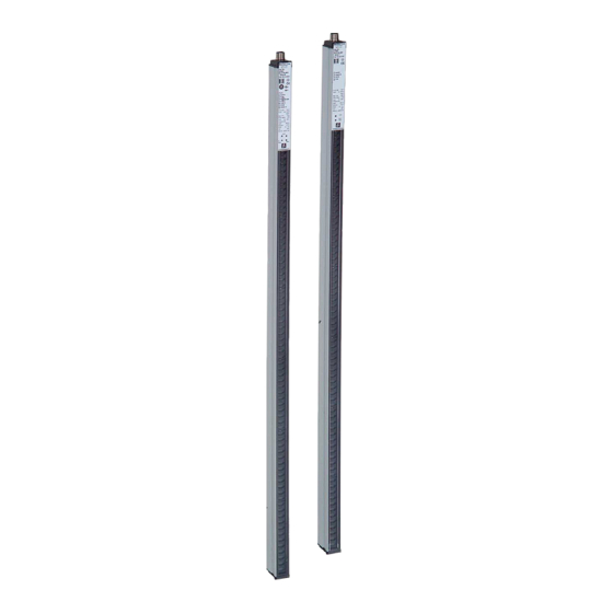
SLCT* and SLCT*/35 safety light curtains Product Description Product Description Use and Application Product description The SLCS safety light curtain is noncontact electro-sensitive protective equipment (ESPE) for securing danger zones and hazardous areas. The SLCT safety light curtain consists of a transmitter unit and receiver unit. The protection field is formed by infrared light beams sent from the transmitter unit to the receiver unit. - Page 10 Selectable relay monitor Simple layout Two OSSDs Further information about the product The following information about the SLCT series is provided in the appendix at the end of this document: Technical data: . Available profile lengths/dimensions: see chapter 8.2. Dimensional drawings: see chapter 8.3.
-
Page 11: Indicators And Operating Controls
SLCT* and SLCT*/35 safety light curtains Product Description Indicators and Operating Controls The transmitter has two LEDs to display its operating status. The receiver has five LEDs to display its operating status. Transmitter Receiver 1 Power green 2 Mode A/B, Status yellow 3 OSSD OFF 4 OSSD ON green... - Page 12 SLCT* and SLCT*/35 safety light curtains Product Description Connect the power supply, the fail-safe outputs (OSSD), the status/select output and the inputs for the startup enable, relay monitor and A/B mode to the receiver unit. The housing profile is connected internally with approx. 2.3 MOhm// 33 nF each at +24 V and 0 V.
-
Page 13: Scope Of Delivery
SLCT* and SLCT*/35 safety light curtains Product Description Scope of Delivery The scope of delivery includes: Scope of delivery: transmitter Transmitter Scope of delivery: receiver Receiver I/O Manual Test rod Bracket and cable are not included in the scope of delivery. Visit www.pepperl- fuchs.com for a selection of compatible fixing brackets and recommended cables. -
Page 14: Installation
SLCT* and SLCT*/35 safety light curtains Installation Installation Planning and Preparation Warning! Danger to life due to ineffective protective equipment Improper or incorrect alignment, fixing, and connection to machine control can impair the effectiveness of the protective function. Note the applicable standards, guidelines, and legal regulations for the equipment of machine and plants with protective equipment. - Page 15 SLCT* and SLCT*/35 safety light curtains Installation To comply with the necessary distances in the event that the protection field spreads, please refer to Table 1 of ISO/EN 13855 to check the minimum distance for a vertically positioned protection field. If you read the value 0 from the table, you can determine the minimum distance with the following formula: S = K x T + C Where, for a protection field aligned vertically to the hazardous area:...
- Page 16 SLCT* and SLCT*/35 safety light curtains Installation Response times of the safety light curtain The safety light curtain response time is shown on the nameplate. 1000 1100 1200 1300 1400 1500 1600 1700 1800 1900 2000 2100 2200 2300 2400...
- Page 17 SLCT* and SLCT*/35 safety light curtains Installation The switch-on time after beam interruption without a restart function is between 80 ms and 200 ms. The switch-on time depends on the number of protective beams. Notes on setting up safety light curtains The protective equipment must be arranged in such a manner that it is impossible to reach over, reach under, or walk behind the protection field.
-
Page 18: Mounting
SLCT* and SLCT*/35 safety light curtains Installation Mounting Warning! Danger to life due to ineffective protective equipment Improper or incorrect alignment, fixing, and connection to machine control can impair the effectiveness of the protective function. Check the positioning of the protective equipment and ensure that it is not possible for persons to reach or walk behind it, climb over, under or otherwise bypass the protective equipment. - Page 19 SLCT* and SLCT*/35 safety light curtains Installation Vertical approach Protective field Danger Distance S zone Figure 4.2 Explanation of the safety distance in a vertical arrangement of the protective field Where K = 2000 mm/s and C = 0 mm, e.g., for SLCT14... or C = 128 mm, e.g., for SLCT30...
- Page 20 SLCT* and SLCT*/35 safety light curtains Installation Parallel approach Protective field Distance S Danger zone H (height above ground) Figure 4.3 Explanation of the safety distance in a horizontal arrangement of the protective field If the safety light curtain is aligned in a horizontal position, the safety distance S will also depend on the height of the light curtain above the floor.
-
Page 21: Reflection
SLCT* and SLCT*/35 safety light curtains Installation Reflection Danger! Danger to life due to reflection If you do not comply with the minimum distances, objects or persons cannot be safely detected in the beams of the protective equipment. When aligning the protective equipment, ensure that the minimum distance to reflective objects or surfaces on all sides of the protection field is observed. -
Page 22: Connection And Operating Mode Setting
SLCT* and SLCT*/35 safety light curtains Installation Danger! Danger to life due to indirect dispersion of light during operation below the specific minimum range If you operate the protective equipment below its specified minimum range, this can lead to reflection caused by reflective or dispersive objects outside the specified minimum distances. -
Page 23: Signal Outputs On The Receiver Unit
SLCT* and SLCT*/35 safety light curtains Installation The function can be activated or deactivated at the 8 pin connector of the receiver SLCT. The two feedback contacts on the external switching elements must be placed between 24 VDC and the relay monitor input in order to activate the relay monitor. The relay monitor function is deactivated if the relay monitor input is bridged with the status/select output. -
Page 24: Signal Inputs On The Transmitter Unit
SLCT* and SLCT*/35 safety light curtains Installation 4.4.2 Signal Inputs on the Transmitter Unit Test input Connect the test input to 24 VDC via an NC contact. The test function is triggered by opening the contact. Note! During operation without a startup/restart interlock, the test time must be limited to 150 ms. -
Page 25: Signal Inputs On The Receiver Unit
SLCT* and SLCT*/35 safety light curtains Installation After the supply voltage is switched on, the transmitter or receiver unit selects mode A or mode B, depending on the applied voltage. Note! Make sure that the transmitter unit and receiver unit are operating in the same mode. - Page 26 SLCT* and SLCT*/35 safety light curtains Installation Relay monitor input Auxiliary contacts on switching elements connected downstream of the OSSDs can be connected to the relay monitor input. This allows these elements to be monitored. Use NC contacts (see chapter 4.4.4). All monitored switching elements must be connected in series.
-
Page 27: Typical Circuits
SLCT* and SLCT*/35 safety light curtains Installation 4.4.4 Typical circuits 24 V K2.1 Transmitter unit Receiver Restart unit K1.1 24 V 24 V Relay monitor Mode A/B Status / Select OSSD1 Test OSSD2 Mode A/B Figure 4.6 Connection example with relay monitor and restart in Mode A 24 V Transmitter unit Receiver... -
Page 28: Commissioning
SLCT* and SLCT*/35 safety light curtains Commissioning Commissioning Functional Testing Check the function of the transmitter and receiver 1. Check whether the transmitter and receiver are aligned parallel to one another and are at the same height. 2. Switch on the safety light curtain when the protection field is clear. 3. -
Page 29: Multiple Positions
SLCT* and SLCT*/35 safety light curtains Commissioning Multiple Positions Note! If several safety light curtains/safety light grids are operating close to each other, care must be taken to prevent any cross-talk. You can use the operating modes "A" and "B" to prevent cross-talk. The illustration below shows a preferred layout. - Page 30 SLCT* and SLCT*/35 safety light curtains Commissioning When operating two safety light curtains with different modes A and B, another arrangement is possible by positioning the transmitter units and receiver units directly on top of each other. The connector plugs extend outwards in the opposite direction.
-
Page 31: Maintenance And Repair
SLCT* and SLCT*/35 safety light curtains Maintenance and Repair Maintenance and Repair Maintenance The safety light curtain is maintenance free. The prescribed periodic checks must be carried out and documented. The checks to determine whether the components are fitted securely and whether the optical surfaces are clean are important. -
Page 32: Repairs
Using a defective or repaired device can compromise its function and its electrical safety. Do not use a damaged or polluted device. The device must not be repaired, changed or manipulated. If there is a defect, always replace the device with an original device from Pepperl+Fuchs. -
Page 33: Troubleshooting
Replace the defective device with an original device from Pepperl+Fuchs. Send the defective device to Pepperl+Fuchs with a description of the fault. Warning! Danger to life as the result of an absence of functional inspections... - Page 34 SLCT* and SLCT*/35 safety light curtains Troubleshooting Eliminating Interference Source of fault Cause Action Transmitter: External fault: a) Check test sequence Status indicator flashes a) Test signal faulty b) Check wiring A/B input mode at 1 Hz b) A/B mode input error Transmitter: Internal error Briefly interrupt power supply or...
-
Page 35: Appendix
SLCT* and SLCT*/35 safety light curtains Appendix Appendix Technical Data General data SLCT*/35 SLCT* Increased detection Standard detection range range Effective operating 0.2 ... 8 m 5 ... 20 m distance Light emitter IRED IRED Light type Infrared, modulated light, Infrared, modulated light, 850 nm 850 nm... - Page 36 SLCT* and SLCT*/35 safety light curtains Appendix Electrical data SLCT*/35 SLCT* Increased detection Standard detection range range Operating voltage 24 VDC (-20 %, +30 %); 24 VDC (-20 %, +30 %); power supply with safe power supply with safe isolation: 24 VDC isolation: 24 VDC The upstream power The upstream power...
- Page 37 SLCT* and SLCT*/35 safety light curtains Appendix SLCT*/35 SLCT* Increased detection Standard detection range range Switching voltage 24 VDC (acting on the 24 VDC (acting on the contact) contact) Input current 5 mA 5 mA Actuation time 0.2 ... 1.2 s 0.2 ...
-
Page 38: Standards And Data For Functional Safety
SLCT* and SLCT*/35 safety light curtains Appendix Mechanical data SLCT*/35 SLCT* Increased detection Standard detection range range Housing length L Connection Transmitter unit: Transmitter unit: connector plug M12 x 1, connector plug M12 x 1, 4 pin 4 pin Receiver unit: connector Receiver unit: connector plug M12 x 1, 8 pin plug M12 x 1, 8 pin... -
Page 39: Profile Lengths And Mass
SLCT* and SLCT*/35 safety light curtains Appendix SLCT*/35 SLCT* Increased detection Standard detection range range SLCT14-300 1.0E-07 SLCT14-600 SLCT14-900 SLCT14-1200 SLCT30-600 1.0E-07 SLCT30-900 SLCT30-1200 SLCT30-1800 SLCT30-2400 SLCT60-1200 SLCT60-2400 SLCT90-1200 SLCT90-2400 The PFH values specified apply up to the maximum ambient temperature. For unlisted versions, the next-largest protection field height specified in the table applies when the resolution of the PFH value is the same. - Page 40 SLCT* and SLCT*/35 safety light curtains Appendix Overall length of the transmitter / receiver unit Weight of transmitter / Protection field height [mm] [mm] receiver unit [g] 1019 1000 1119 1100 1219 1200 1319 1300 1425 1400 1525 1500 1625 1600 1725 1700...
-
Page 41: Dimensional Drawing
Dimensions of the safety light curtain at ≤ 1300 mm Type Code Safety light curtains from the SLCT series are designated a code according to the following format: S L C T XX - YYYY - Z - AAAA /35 Here, XX represents the obstacle size, YYYY the protection field height, Z the device type, i.e. - Page 42 SLCT* and SLCT*/35 safety light curtains Appendix Protection field Building Detection Obstacle size height Device type regulation range XX [mm] YYYY [mm] AAAA 100, 200, 300, T, R Standard 1200 specification 100, 200, 300, T, R Standard 2400 specification Increased detection range "/35"...
- Page 43 SLCT* and SLCT*/35 safety light curtains Appendix Type code "SCLT30-* (obstacle size 30 mm) - standard detection range Protection field height [mm] Complete Transmitter unit (-T) Receiver unit (-R) SLCT30-100 SLCT30-100-T SLCT30-100-R SLCT30-200 SLCT30-200-T SLCT30-200-R SLCT30-300 SLCT30-300-T SLCT30-300-R SLCT30-400 SLCT30-400-T SLCT30-400-R SLCT30-500 SLCT30-500-T...
- Page 44 SLCT* and SLCT*/35 safety light curtains Appendix Type code "SCLT30-* (obstacle size 30 mm) - increased detection range Protection field height [mm] Complete Transmitter unit (-T) Receiver unit (-R) SLCT30-100/35 SLCT30-100-T/35 SLCT30-100-R/35 SLCT30-200/35 SLCT30-200-T/35 SLCT30-200-R/35 SLCT30-300/35 SLCT30-300-T/35 SLCT30-300-R/35 SLCT30-400/35 SLCT30-400-T/35 SLCT30-400-R/35 SLCT30-500/35 SLCT30-500-T/35...
- Page 45 SLCT* and SLCT*/35 safety light curtains Appendix Type code "SCLT60-* (obstacle size 60 mm) - standard detection range Protection field height [mm] Complete Transmitter unit (-T) Receiver unit (-R) SLCT60-300 SLCT60-300-T SLCT60-300-R SLCT60-600 SLCT60-600-T SLCT60-600-R SLCT60-900 SLCT60-900-T SLCT60-900-R 1200 SLCT60-1200 SLCT60-1200-T SLCT60-1200-R 1500...
- Page 46 SLCT* and SLCT*/35 safety light curtains Appendix Type code "SCLT90-* (obstacle size 90 mm) - increased detection range Protection field height [mm] Complete Transmitter unit (-T) Receiver unit (-R) SLCT90-300/35 SLCT90-300-T/35 SLCT90-300-R/35 SLCT90-600/35 SLCT90-600-T/35 SLCT90-600-R/35 SLCT90-900/35 SLCT90-900-T/35 SLCT90-900-R/35 1200 SLCT90-1200/35 SLCT90-1200-T/35 SLCT90-1200- R/35...
-
Page 47: Application Checklist
SLCT* and SLCT*/35 safety light curtains Appendix Application Checklist A list of important points should help you avoid errors when planning, setting up, and using the protective equipment. This application checklist is not complete and must be modified to suit each specific application. Note! Observing Applicable Standards and Laws The relevant laws and standards that apply to the use of opto-electronic safety... - Page 48 SLCT* and SLCT*/35 safety light curtains Appendix Periodic check Have the requisite tests and test intervals been determined? Is the detection capability of the SLCT tested regularly over the entire protection field height using the test rod? Are the response times checked at regular intervals? Is all machine safety equipment inspected at the required intervals? Are all inspections documented?
-
Page 49: Accessories
SLCT* and SLCT*/35 safety light curtains Appendix Accessories The following products are available as accessories: Matching accessories for safety light curtains Designation Illustration Description OMH-SLCT-01 Mounting Aid OMH-SLCT-02 Mounting Aid OMH-SLCT-03 Mounting Aid OMH-SLCT-04 Mounting Aid OMH-SLCT-05 Mounting Aid... - Page 50 SLCT* and SLCT*/35 safety light curtains Appendix Designation Illustration Description OMH-SLCT-10 Mounting Aid OMH-SLCT-11 Mounting Aid OMH-SLCT- Muting arm with round 12-500 OMH-07-01 Light barrier holder for muting round rod...
- Page 51 SLCT* and SLCT*/35 safety light curtains Appendix Designation Illustration Description OMH-SLCT- Mounting profile for 100-1200 floor mounting OMH-SLCT- 100-1500 OMH-SLCT- 100-2100 OMH-SLCT- 100-2500...
- Page 52 SLCT* and SLCT*/35 safety light curtains Appendix Designation Illustration Description OMH-SLCT- Mounting profile with 110-1200 decorative cover (front) OMH-SLCT- 110-1500 OMH-SLCT- 110-2100 OMH-SLCT- 110-2500...
- Page 53 SLCT* and SLCT*/35 safety light curtains Appendix Designation Illustration Description OMH-SLCT- Two lateral protective 120-1200 covers for mounting profile OMH-SLCT- 120-1500 OMH-SLCT- 120-2100 OMH-SLCT- 120-2500 OMH-SLCT- Floor mount for soil column/mounting profile...
- Page 54 SLCT* and SLCT*/35 safety light curtains Appendix Designation Illustration Description SLCT-M-01- Inclined mirror for 90° 1200 deflection SLCT-M-01- 1500 SLCT-M-01- 2100 SLCT-M-01- 2500 AA SLCT-01 Profile alignment aid Test rod 14/30/50/60...
-
Page 55: Mounting Aid Omh-Slct-01
The mounting brackets are also suitable as a corner profile if two independently acting light curtains are to be installed. For compatible mounting brackets, use the search term SLCT-M*. on www.pepperl+fuchs.com. 8.6.1 Mounting Aid OMH-SLCT-01... -
Page 56: Mounting Brackets Omh-Slct-03 And Omh-Slct-04
Model number: OMH-SLCT-05 The OMH-SLCT-05 mounting aid is a robust, swiveling holder with very large pivoting range. The integrated dovetail groove terminal device enables the mounting of profiles from the SLCS or SLCT series without any additional accessories. Features Large pivoting range from -7° .. +110°... -
Page 57: Omh-Slct-100-Xxxx Mounting Profile For Floor Mounting
SLCT* and SLCT*/35 safety light curtains Appendix 8.6.7 OMH-SLCT-100-xxxx Mounting profile for floor mounting Eight grooves for mounting photoelectric sensors or accessories, three on the inside and five on the outside Corner mounting of photoelectric sensors with a directional difference of 90°... -
Page 58: Slct-M-01-Xxxx Inclined Mirror For 90° Deflection
SLCT* and SLCT*/35 safety light curtains Appendix 8.6.11 SLCT-M-01-xxxx inclined mirror for 90° deflection Features Rotation-invariant deflection of a light beam by 90° in the plane of incidence, making it highly vibration-resistant Translation-free deflection with no lateral beam shift with OMH-SLCT-200 floor mount Silver-coated mirror glass Mirror glass with low light absorption... -
Page 59: Test Rod
SLCT* and SLCT*/35 safety light curtains Appendix 8.6.13 Test rod Order designation: TR 14/30/50/60 The detection capability of a safety light curtain should be checked regularly using a test rod. The test rod must be kept in the same location as the safety light curtain. -
Page 60: Connection Cables
SLCT* and SLCT*/35 safety light curtains Appendix 8.6.14 Connection Cables Various 4-pin and 8-pin connection cables are available in a range of lengths. Connection cables are not included in the scope of delivery of a safety light curtain. Connection cable for safety light curtains Model number Length 2 m Length 5 m... - Page 61 Twinsburg, Ohio 44087 · USA Tel. +1 330 4253555 E-mail: sales@us.pepperl-fuchs.com Asia Pacific Headquarters Pepperl+Fuchs Pte Ltd. Company Registration No. 199003130E Singapore 139942 Tel. +65 67799091 E-mail: sales@sg.pepperl-fuchs.com www.pepperl-fuchs.com Subject to modifications Copyright PEPPERL+FUCHS • Printed in Germany 271695 DOCT-3848A 12/2017...
Need help?
Do you have a question about the SLCT Series and is the answer not in the manual?
Questions and answers