Advertisement
Quick Links
Table of Contents
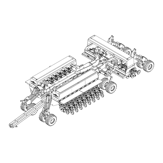
3N-4010P, 3N-4010HDP, 3N-4020P and 3N-4025P
3-Section 40-Foot No-Till Precision Drills
Read the operator manual entirely. When you see this symbol, the subsequent
!
instructions and warnings are serious - follow without exception. Your life and
the lives of others depend on it!
Illustrations may show optional equipment not supplied with standard unit or
may depict similar models where a topic is identical.
ORIGINAL INSTRUCTIONS
© Copyright 2019
Table of Contents
Index
Operator Manual
Manufacturing, Inc.
www.greatplainsmfg.com
Printed 2019-03-14
Index
2014+
20293
EN
196-538M
Advertisement

Subscribe to Our Youtube Channel
Related Manuals for GREAT PLAINS 3N-4010P


Summary of Contents for GREAT PLAINS 3N-4010P
- Page 1 Table of Contents Index Operator Manual 3N-4010P, 3N-4010HDP, 3N-4020P and 3N-4025P 2014+ 3-Section 40-Foot No-Till Precision Drills Manufacturing, Inc. www.greatplainsmfg.com Read the operator manual entirely. When you see this symbol, the subsequent instructions and warnings are serious - follow without exception. Your life and...
- Page 2 The QR Code (Quick Response) to the left will take you to available dealers for left will take you to this machine’s family Great Plains products. Refer to the of manuals. Use your smart phone or Parts Manual QR Locater for detailed tablet to scan the QR Code with an instructions.
- Page 3 Great Plains Manufacturing, Inc. assumes no responsibility for errors or omissions. Neither is any liability assumed for damages resulting from the use of the information contained herein. Great Plains Manufacturing, Inc. reserves the right to revise and improve its products as it sees fit.
- Page 4 25 Series Disk Blade Adjustments ......119 Appendix ................170 25 Series Side Gauge Wheel Scrapers....120 Specifications and Capacities ........170 25 Series Seed Firmer Adjustments.......121 3N-4010P Specifications and Capacities ....170 ® 25 Series Seed-Lok Lock-Up .......121 3N-4010HDP Specifications and Capacities..171 25 Series Press Wheel Adjustments ......122 3N-4020P Specifications and Capacities ....172...
- Page 5 3N-40P Table of Contents Index Important Safety Information Important Safety Information Look for Safety Symbol The SAFETY ALERT SYMBOL indicates there is a potential hazard to personal safety involved and extra safety precaution must be taken. When you see this symbol, be alert and carefully read the message that follows it.
- Page 6 3N-40P Table of Contents Index Important Safety Information Wear Protective Equipment Wear protective clothing and equipment. Wear clothing and equipment appropriate for the job. Avoid loose-fitting clothing. Because prolonged exposure to loud noise can cause hearing impairment or hearing loss, wear suitable hearing protection such as earmuffs or earplugs.
- Page 7 3N-40P Table of Contents Index Important Safety Information Use A Safety Chain Use a safety chain to help control drawn machinery should it separate from tractor drawbar. Use a chain with a strength rating equal to or greater than the gross weight of towed machinery.
- Page 8 3N-40P Table of Contents Index Important Safety Information Transport Machinery Safely Maximum transport speed for drill is 20 mph (32 kph). Some rough terrains require a slower speed. Sudden braking can cause a towed load to swerve and upset. Drill must be raised, locked-up, folded and locked for transport.
- Page 9 3N-40P Table of Contents Index Important Safety Information Tire Safety Tire changing can be dangerous and should be performed by trained personnel using correct tools and equipment. When inflating tires, use a clip-on chuck and extension hose long enough for you to stand to one side–not in front of or over tire assembly.
- Page 10 Keep all safety decals clean and legible. Replace all damaged or missing decals. Order new decals from your Great Plains dealer. Refer to this section for proper decal placement. When ordering new parts or components, also request corresponding safety decals.
- Page 11 3N-40P Table of Contents Index Important Safety Information Daytime Reflectors 838-267C On the outside edge of center walkboard each end; 2 total 21791 Danger: Cannot Read English 818-557C PELIGRO Si No Lee Ingles, Pida Ayuda a Alugien Que Si Lo Lea Para Que le Traduzca las Medidas de Seguridad.
- Page 12 3N-40P Table of Contents Index Important Safety Information Warning: Pinch/Crush 818-045C On transport wheel assembly; 21791 4 total 21791 Warning: Speed Hazard 818-188C WARNING EXCESSIVE SPEED HAZARD To Prevent Serious Injury or Death: Do Not exceed 20 mph maximum transport speed.
- Page 13 3N-40P Table of Contents Index Important Safety Information Warning: Pinch Point 818-579C (Option) On marker, two with single, four with dual marker option; 2 or 4 total 20306 Warning: Overhead Hazard 818-580C (Option) On marker, two with single, four with dual marker option; 2 or 4 total 20306 Caution: Tires Not A Step...
- Page 14 3N-40P Table of Contents Index Important Safety Information Caution: General 818-587C On tongue near hitch; 1 total 21791 Caution: Pressure/Torque 838-426C On the rim of each tire; 12 total 21791 2019-03-14 Table of Contents Index 196-538M...
- Page 15 3N-40P Table of Contents Index Introduction Introduction Great Plains welcomes you to its growing family of new product owners. Your 3-Section 40-Foot No-Till Precision Drill has been designed with care and built by skilled workers using quality materials. Proper setup, maintenance, and safe operating practices will help you get years of satisfactory use.
- Page 16 Great Plains parts. Always use the serial and model number when ordering parts from your Great Plains dealer. The serial number plate is located on the front of the left hand side of the center section.
- Page 17 3N-40P Table of Contents Index Preparation and Setup Preparation and Setup This section will help you prepare your tractor and drill for use. Before using the drill in the field, you must hitch the drill to a suitable tractor and level the drill. Pre-Setup Checklist 1.
- Page 18 Refer to Figure 4 Great Plains hydraulic hoses have color coded handle grips to help you hookup hoses to your tractor outlets. Hoses that go to the same remote valve are marked with the same color.
- Page 19 3N-40P Table of Contents Index Preparation and Setup Older Style Hoses with Color Ties Refer to Figure 6 Hoses that go to the same remote valve are marked with the same color tie. To distinguish hoses on the same hydraulic circuit, refer plastic hose label.
- Page 20 3N-40P Table of Contents Index Preparation and Setup Electrical Hookup Plug drill electrical lead into tractor seven-pin connector. If your tractor is not equipped with an ASAE J560b seven-pin connector, contact your dealer for installation. Plug optional connectors aftermarket connectors, such as an drill-mounted GPS receiver. For future reference, note any optional connectors on this checklist.
- Page 21 3N-40P Table of Contents Index Preparation and Setup Initial Setup The following items need to be done for first use, and some need to be re-done if the tractor changes. Initial Tractor Setup Three modules are mounted in the tractor cab. Route harnesses clear of moving parts, and allow enough slack for turns, especially on articulated tractors.
- Page 22 Although the drill includes a radar sensor, it is connected to the hydraulic drive system, and does not include Y-cable to share it with the seed monitor. Great Plains recommends connecting the seed monitor to a separate speed sensor, usually tractor-mounted.
- Page 23 3N-40P Table of Contents Index Preparation and Setup Refer to Figure 13 At the parameter 4 screen (Row Width), enter the row spacing of the drill (in inches or cm, to 0.1 precision). Use the base row spacing, even if re-configuring for twin row or split row operation.
- Page 24 Install any that were not pre-installed. Scrapers (Option) If scrapers were ordered, and not dealer-installed, install them now per the instructions in one of the following manuals, which are available on the Great Plains website if not ordered or included: Figure 17: 122-259K 20162 10 &...
- Page 25 Refer to Figure 230 through Figure 235 on pages 176 and 178 4. Check measurement against value recommended by Great Plains. Figure 18 18878 Adjusting Marker Extension Refer to Figure 18 If the marker extensions need adjustment: 5. Loosen the nuts...
- Page 26 3N-40P Table of Contents Index Preparation and Setup Install Outer Brackets Start with the left wing. Refer to Figure 20 1. Select two: 806-172C U-BOLT 3/4-10 X 10 1/32X11 1/2 From the front of the wing, insert the U-Bolts through the holes in the outside lug 2.
- Page 27 3N-40P Table of Contents Index Preparation and Setup Install Mid-Wing Brackets Refer to Figure 21 5. Select two: 806-172C U-BOLT 3/4-10 X 10 1/32X11 1/2 From the centerline of the inside U-Bolt installed at step 1, measure toward center, approximately: inch (90 cm) Insert a U-bolt from drill front, under the hoses.
- Page 28 3N-40P Table of Contents Index Operating Instructions Operating Instructions This section covers general operating procedures. It assumes that setup items have been completed. Experience, machine familiarity and this information leads to efficient operation and good working habits. Always operate farm machinery with safety in mind. Pre-Start Checklist Review “Important Safety Information”...
- Page 29 3N-40P Table of Contents Index Operating Instructions Lift / Lower Machine Damage Risk: Lower only when the drill is unfolded. The drill must be raised and locked up for folding and unfolding. The drill has six rephasing lift cylinders that raise and lower the opener frame.
- Page 30 3N-40P Table of Contents Index Operating Instructions Lift Cylinder Lock-Up When moving the raised drill more than a short distance, or over any public road, or when performing adjustments or maintenance, do not rely solely on the lift cylinders to keep the mainframe raised.
- Page 31 3N-40P Table of Contents Index Operating Instructions There are two key points to remember when operating the lock cylinders. a. All seven lock cylinders are plumbed together, and all move at the same time. b. Operate the lock circuit lever (Retract/Neutral) only once to fold.
- Page 32 Machine is not grounded. At higher voltages, electrocution can occur without direct contact. Great Plains recommends transporting the drill without seed loaded. Although designed for highway movement with full seed boxes, the additional weight of seed may...
- Page 33 3N-40P Table of Contents Index Operating Instructions Make sure the tractor weighs at least (67%) of the drill, including any material load. Check the table on page 30 for typical weights of various configurations. Loss of Control Hazard: Towing the drill at high speeds or with a vehicle that is not heavy enough can lead to loss of vehicle control.
- Page 34 3N-40P Table of Contents Index Operating Instructions Typical Drill Weights a. Weights include frame-mounted coulters and typical press wheels, but not row unit accessories or other options, which can alter the total weight substantially. If table weight is near recommended limit for the tractor, obtain a precise weight for the empty drill at a scale. 2019-03-14 Table of Contents Index...
- Page 35 Watch your step when walking on drill ladder and walkboard. Falling from drill could cause severe injury or death. Great Plains recommends loading materials after the drill has been transported to the planting ground. Seed is heavy. A full load of dense seed adds over 6000 pounds (2780 kg) drill.
- Page 36 For Finger Pick Up Meters Only Use only approved Graphite Powder available from Ezee Glide Plus Talc-Graphite Mix Great Plains Mfg. Inc. or Precision Planting to ensure 821-069C bucket, 5 gallon (19 liter) proper lubrication of finger pickup corn seed meters.
- Page 37 3N-40P Table of Contents Index Operating Instructions Planting Seed Rate Seed rate on this family of drills is controlled by: • selection of seed meter, and seed wheel or finger count, and • the rate set on the hydraulic drive console. About Hydraulic Drive Rate Before it can control seed rate, the hydraulic drive console must be:...
- Page 38 A Point Row troubleshooting chart is found on page 129. Refer to Figure 35 The Pump switch has no function on 3N-40 drills configured by Great Plains. Unless connected to aftermarket equipment, leave it off. When Not Planting or Calibrating Set the Master switch OFF when you do not intend to meter seed.
- Page 39 3N-40P Table of Contents Index Operating Instructions Field Operations This section presumes that all pre-operation checks have been made on drill, and drill is hitched and loaded with seed. Final Field Checklist q Drill unfolded and raised. q Selector valve set to hydraulic drive. q Hydraulic drive console set per seed rate calibration.
- Page 40 3N-40P Table of Contents Index Operating Instructions Marker Operation (Option) Markers are on a separate hydraulic circuit on the drill. Before operating markers, make sure they are properly bled as described in “Bleeding Markers” on page 147. Dual markers are equipped with a sequence valve to control lift sequence.
- Page 41 3N-40P Table of Contents Index Operating Instructions Parking Following these steps when parking the drill for periods of less than 36 hours. For longer periods, see Storage, the next topic. 1. Spot the drill on firm, level ground. 2. Raise the drill. Install transport locks. 3.
- Page 42 3N-40P Table of Contents Index Hydraulic Drive Operation Hydraulic Drive Operation Seeding rate on the 3N-40 family is controlled entirely seed meter wheel selection, and by the seed monitor and the hydraulic drive. This section of the manual describes monitor setup and operation. Drive Operational Requirements Hydraulic System: Closed Center, pressure compensated or load sensed...
- Page 43 3N-40P Table of Contents Index Hydraulic Drive Operation Controller Menu ON / VR set= * spd= out= ______ _._ PRESET RATES FUNCTION PRESET FUNCTION CALIBRATION selected NUMBER * PRESET 1 VARIABLE RATE FUNCTION FUNCTION FUNCTION recipe format RAWSON NOMINAL PRESET 2 RAWSON selected VERIS V1...
- Page 44 3N-40P Table of Contents Index Hydraulic Drive Operation Console Functions Refer to Figure 39 (depicting the console in Manual mode) • ON/VR button: turns drive system on. Press twice for VR (Variable Rate) mode. • OFF button: used to shut off Console. ...
- Page 45 3N-40P Table of Contents Index Hydraulic Drive Operation Hydraulic Drive Field Operations Refer to Figure 40 1. Turn on Controller Console by pressing the ON/VR button. Green light above ON/VR button illuminates when power is on. Pressing the ON/VR button twice puts the unit in VR mode.
- Page 46 SampleSize is 1.04 lbs Load 2 lbs or more for testing. Great Plains suggests sampling an amount that is at least pound (0.1 kg), and requires at least 100 seconds. At typical planting speeds, this is about one row for one acre (or one row for half a hectare).
- Page 47 3N-40P Table of Contents Index Hydraulic Drive Operation Refer to Figure 42 4. Set the Point Row switch box for Calibration mode: • LEFT section switch on. • CENTER and RIGHT section switches off. • Master switch to “CAL” Confirm CAL lamp illuminated.
- Page 48 3N-40P Table of Contents Index Hydraulic Drive Operation Refer to Figure 45 12. Press Function button until the Calibration window appears as shown. 13. Press arrow button to enter calibration mode. Figure 45 28251 Initiate Sample Calibration Refer to Figure 46 14.
- Page 49 3N-40P Table of Contents Index Hydraulic Drive Operation Refer to Figure 48 15. Enter drill width (swath), in feet (ENGLISH mode) or meters (METRIC mode), using / arrow buttons. Press FUNCTION button to advance to next window. Swath values for various row spacings are found in the charts beginning on page 176.
- Page 50 3N-40P Table of Contents Index Hydraulic Drive Operation Prime Seed Meters Before running an actual calibration, it is important that the seed cups be filled with seeds, and the flutes primed to deliver seed at first rotation. Step 18 through step 29 executes a short calibration to do this.
- Page 51 3N-40P Table of Contents Index Hydraulic Drive Operation Refer to Figure 54 21. Press FUNCTION. The console beeps and displays this screen, indicating that the drive is about to operate, and all personnel must be cleared from the area near the hydraulic drive, chains and shafts. There is a danger of entanglement if anyone is in the drive area.
- Page 52 3N-40P Table of Contents Index Hydraulic Drive Operation Refer to Figure 57 26. When the sample run-time has expired, the motor stops, the indicator above the ENGAGE button goes out, and the console displays the estimated sample generated (based on actual motor performance, which may vary slightly from calculations).
- Page 53 3N-40P Table of Contents Index Hydraulic Drive Operation Full Calibration Make sure the seed meter cups are full, and seed can flow at initial motor rotation. To prime the cups, see page 46. Refer to Figure 59 30. Turn the console on with the ON/VR button. Check, and as necessary, repeat step 1 through step 17.
- Page 54 3N-40P Table of Contents Index Hydraulic Drive Operation Refer to Figure 62 34. Press FUNCTION. The console beeps and displays the next screen indicating that the drive is about to operate, and all personnel must be cleared from the area near the hydraulic drive, chains and shafts. There is a danger of entanglement if anyone is in the drive area.
- Page 55 3N-40P Table of Contents Index Hydraulic Drive Operation Refer to Figure 65 38. When the sample run-time has expired, the motor stops, the indicator above the ENGAGE button goes out, and the console displays the estimated sample generated (based on actual motor performance, which may vary slightly from calculations).
- Page 56 3N-40P Table of Contents Index Hydraulic Drive Operation Refer to Figure 67 41. A new calibration number is suggested, along with the old calibration number. Figure 67 28263 New/Old Calibration Number Refer to Figure 68 42. Press FUNCTION button to advance to the choice window.
- Page 57 3N-40P Table of Contents Index Hydraulic Drive Operation Speed Calibration In order to fine-tune the default speed calculation or to convert to radar speed signal, the controller may be calibrated as follows: 1. Set two flags 400 ft.apart (100 meters if in metric mode).
- Page 58 3N-40P Table of Contents Index Hydraulic Drive Operation Refer to Figure 73 5. Begin driving at a normal field speed; when the tractor passes the first flag, press ENGAGE. Figure 73 28268 At First Flag Refer to Figure 74 6. While between flags, the display shows the distance traveled.
- Page 59 3N-40P Table of Contents Index Hydraulic Drive Operation Refer to Figure 76 8. The display shows the error or difference between the traveled distance and the distance calculated by the Controller. Figure 76 28271 Distance Variance Refer to Figure 77 9.
- Page 60 3N-40P Table of Contents Index Hydraulic Drive Operation Varying Rates with Pre-set Function The Precision Population Controller allows you to pre-set three different rates, and then change rates on-the-go by toggling from one rate to another rate with the / arrow buttons.
- Page 61 Measure the distance from the GPS to the seed tubes. Enter the measurement in the Following Distance window. Enter the Swath Width of the Great Plains unit. 6. Under the CTRL tab, enter the Nominal Rate as follows: Divide the highest rate on your recipe by 1.6.
- Page 62 3N-40P Table of Contents Index Hydraulic Drive Operation GP Precision Population Settings 1. Connect SiteMate computer to Console using 9-pin serial cable , as shown in Figure 83. Follow instructions on page 42 to set Calibration Number. Refer to Figure 84 2.
- Page 63 SRAM or Flash card that is compatible with the PF 3000. PF3000 Settings: 2. Press SETUP key. Press SWATH key. Set swath to that of your Great Plains Precision Seeding System. 3. Press SETUP key. Press VEHICLE key. Figure 86: PF3000: 28322 Set Primary speed sensor to GPS.
- Page 64 3N-40P Table of Contents Index Hydraulic Drive Operation Precision Population Settings 1. Connect PF3000 to Console using 9 pin serial cable per Figure 86 on page 59. 2. Set Calibration Number per page 42. Refer to Figure 87 3. Press FUNCTION button until a “recipe” screen appears.
- Page 65 3N-40P Table of Contents Index Hydraulic Drive Operation Seeding Charts Seed Wheel Selection Chart 34192 2019-03-14 Table of Contents Index 196-538M...
- Page 66 3N-40P Table of Contents Index Hydraulic Drive Operation Veris CAL Numbers (Singulated) MAX ALLOWABLE POPULATION AT SELECTED SPEEDS. TO ASSURE HIGH RANGE: MOTOR 21T DRIVER - MAIN- ACCURATE METER OPERATION, DO NOT APPLY AT RATES HIGHER SHAFT 17T DRIVEN THAN LISTED LIMIT. CROP ROW SPACE METER TYPE...
- Page 67 3N-40P Table of Contents Index Hydraulic Drive Operation Veris Initial CAL Numbers (Volumetric) MAX ALLOWABLE POPULATION AT SELECTED SPEEDS. TO ASSURE LOW RANGE: MOTOR 21T DRIVER - MAIN- ACCURATE METER OPERATION, DO NOT APPLY AT RATES HIGHER SHAFT 34T DRIVEN THAN LISTED LIMIT.
- Page 68 3N-40P Table of Contents Index Hydraulic Drive Operation Seeding Range, 20 Inch Rows, 12 Finger Meter 20” Row Spacing For Round Corn optimum meter speed is 45 to 75 RPM Calibration Number For Flat Corn optimum meter speed is 65 to 75 RPM ( Shaded Area) 1492 Ground Speed High Range...
- Page 69 3N-40P Table of Contents Index Hydraulic Drive Operation Seeding Range, 30 Inch Twin Row, 6 Finger Meter (1 of 2) Twin Row 30” For Round Corn optimum meter speed is 45 to 75 RPM Calibration Number For Flat Corn optimum meter speed is 65 to 75 RPM ( Shaded Area) Ground Speed High Range 7 mph...
- Page 70 3N-40P Table of Contents Index Hydraulic Drive Operation Seeding Range, 30 Inch Twin Row, 6 Finger Meter (2 of 2) Twin Row 30” For Round Corn optimum meter speed is 45 to 75 RPM Calibration Number For Flat Corn optimum meter speed is 65 to 75 RPM ( Shaded Area) Ground Speed High Range 7 mph...
- Page 71 3N-40P Table of Contents Index Hydraulic Drive Operation Seeding Range, 30 Inch Twin Row, 12 Finger Meter Twin Row 30” For Round Corn optimum meter speed is 45 to 75 RPM Calibration Number For Flat Corn optimum meter speed is 65 to 75 RPM ( Shaded Area) 1990 Ground Speed High Range...
- Page 72 3N-40P Table of Contents Index Hydraulic Drive Operation Seeding Range, 30 Rows, 6 Finger Meter 30” Row Spacing For Round Corn optimum meter speed is 45 to 75 RPM Calibration Number For Flat Corn optimum meter speed is 65 to 75 RPM ( Shaded Area) Ground Speed High Range 7 mph...
- Page 73 3N-40P Table of Contents Index Hydraulic Drive Operation Seeding Range, 30 Rows, 12 Finger Meter (1 of 2) 30” Row Spacing For Round Corn optimum meter speed is 45 to 75 RPM Calibration Number For Flat Corn optimum meter speed is 65 to 75 RPM ( Shaded Area) Ground Speed High Range 7 mph...
- Page 74 3N-40P Table of Contents Index Hydraulic Drive Operation Seeding Range, 30 Rows, 12 Finger Meter (1 of 2) 30” Row Spacing For Round Corn optimum meter speed is 45 to 75 RPM Calibration Number For Flat Corn optimum meter speed is 65 to 75 RPM ( Shaded Area) Ground Speed High Range 7 mph...
- Page 75 Setting nominal planting depth, and achieving it provide adjustments for optimal field results. consistently, is affected by multiple adjustable drill The 3N-4010P, 3N-4010HDP, 3N-4020P and 3N-4025P functions, from greatest to least effect they are: have double-disk...
- Page 76 3N-40P Table of Contents Index Adjustments Frame Level When beginning planting, check frame level with row units in level ground. If one or both wings are angled up or down, check and adjust the following items: • “Level Frame Side to Side” on page 142 •...
- Page 77 Opener Conditions Unit Tool Bar Height Light no-till, or 3N-4010HDP Above 26 in. (66 cm) conventional tillage, 3N-4010P Above 24 in. (61 cm) with unit-mounted 3N-4020P Above 24 in. (61 cm) coulters or no 3N-4025P Above 24 in. (61 cm)
- Page 78 3N-40P Table of Contents Index Adjustments Refer to Figure 91 The lift system includes an adjustable stop valve to fix the height of the opener frame when the drill is lowered. Make sure the drill is level and the lift system bled and re-phased before adjusting the tool bar height.
- Page 79 3N-40P Table of Contents Index Adjustments Frame-Mounted Coulters The factory configuration of frame-mounted coulters (FMC) is to run about 1 inch (2.5 cm) deeper than the opener blades. Based your conditions experience, you can readjust the depth drill-wide, or just at some rows.
- Page 80 3N-40P Table of Contents Index Adjustments Crushing Hazard: Make all down-stop adjustments with circuit in neutral and drill raised (actuator plunger not in contact with down-stop). Loosening the down-stop with circuit active and drill lowered results in rapid lowering of the frame. Height Mis-setting Risk: Make sure the drill is level and the lift system bled and re-phased before adjusting the tool bar height.
- Page 81 3N-40P Table of Contents Index Adjustments 7. Measure the depth at which the coulters are running. Measure only in non-tire-track rows where the coulter springs are not in compression (arm is at full extension). If the coulters are at the desired depth, ...
- Page 82 3N-40P Table of Contents Index Adjustments Frame-Mounted Coulter Force Coulter springs are set to 400 pounds (181 kg). In normal operation at target running depth, the spring is at full extension. It compresses briefly as obstructions are encountered. • In heavy no-till conditions, you may observe the springs in compression most of the time.
- Page 83 On 10HD and 25 Series openers, you can also entirely change the meter as your crop mix changes. All models support: • Great Plains Singulator Plus™ meters The 3N4010HDP and 3N4025 further support: • Finger pick-up meters. The 3N-40 does not support feeder cups. Use a...
- Page 84 Seed meter wheels for the 10HD and 25P Series row units are made of a green color material and are not interchangeable with the other Great Plains seed meter wheels, such as Black for 20P Series. Use only green wheels in 10HD and 25P Series...
- Page 85 3N-40P Table of Contents Index Adjustments Refer to Figure 103 3. Pry the seed meter wheel out about inch (6 mm) using the tool stored under the walkboard, and spin backward to clean out seeds from top pockets. If wheel is not free of all seed, wheel removal is much more difficult, as pocketed seeds will shear against meter parts.
- Page 86 3N-40P Table of Contents Index Adjustments Meter Installation Applies only to 10HD and 25 Series openers. Installation is the reverse of the removal process, with two steps omitted. Refer to Figure 106 1. Insert the meter. Insert the top meter tab (with the hook). Align the meter base with the latch plate ears.
- Page 87 “skips” (delivering no seed on some fingers). As needed, adjust for minimal doubles and skips. These instructions describe the current finger pickup meter shipped with new Great Plains drills, with an integrated adjustment lever for the brush. If you have added pre-existing finger meters after purchase,...
- Page 88 However, there are two alternative inserts that can be used. Before changing to a different insert, please consult with a Great Plains service representative for a recommendation. The identification of the insert type is molded into the back of the insert.
- Page 89 3N-40P Table of Contents Index Adjustments Finger Meter Sprocket Indexing (Stagger) This topic applies only to finger meters. 28420 If you are planting: • finger-metered, • twin-row crops, • at seed interval spacings above 6 inches (16.5 cm), you can synchronize each pair of adjacent meters in a twin row so that you achieve the maximum seed-to-seed spacing between the units of the pair.
- Page 90 3N-40P Table of Contents Index Adjustments Sprocket Indexing Charts 1. For: your 6- or 12-finger meter, and your twin row spacing (30in on this page) find your seed rate in the Population column, or your seed spacing in the Seed Not Rate or Spacing Charts: Spacing column.
- Page 91 3N-40P Table of Contents Index Adjustments Indexing Fine Adjustment If, after indexing, the twin-row side-to-side seed stagger 28421 is substantially imbalanced, it is possible to make small adjustments that may correct it. Imbalance can occur over time as row unit chains wear and stretch. The procedure is different for 6- and 12-finger meters.
- Page 92 3N-40P Table of Contents Index Adjustments 12-Finger Meter Stagger Adjustment Before making any Indexing Adjustments, check actual planted seed spacing. Seed Spacing is found by 28422 measuring the distance between 25 correctly planted seeds in one row and dividing by 24. (A visible skip or double should be counted as one seed.) Make sure current front index is 1, and current rear sprocket index number matches the number in the indexing chart for...
- Page 93 Seed meter wheels for the 20 Series row units are made of a black color material and are not interchangeable with the other Great Plains seed meter wheels for other machines. Use only black wheels in 20 Series row units.
- Page 94 3N-40P Table of Contents Index Adjustments Refer to Figure 115 With the seed meter wheel removed, you may want to check the meter for internal damage or trash. Some wear on top edge of slide is normal. Excess wear is cause for replacement.
- Page 95 3N-40P Table of Contents Index Adjustments To adjust the row cleaner: 1. Determine the height adjustment required. Measure from the lowest tine to the ground. Determine the desired new measurement. 2. Support most or all of the weight of the arm to prevent injury and ease the adjustment.
- Page 96 3N-40P Table of Contents Index Adjustments Refer to Figure 119 5. Loosen the cam clamp on the rockshaft and turn until the switch roller is just starting to make contact with the ramp surface Figure 119 15160 Implement Lift Cam Adjust Refer to Figure 119 6.
- Page 97 Each bracket accepts up to five standard weights, about 500 lbs (227 kg) per wing, or 1000 lbs (454 kg) per kit. Great Plains recommends loading no more than two sets of brackets, representing 2000 lbs (907 kg) total. Do not add weight to the center section. It is always heavier than even a fully weighted wing, and never requires additional weights.
- Page 98 3N-40P Table of Contents Index Adjustments Marker Adjustments This section covers marker items that may need adjustment for current conditions, and assumes that the markers are installed, set to the correct initial extension and in proper working order. See also: •...
- Page 99 (which depicts a row unit fully populated with most optional accessories supported for use with the 3N-4010P drill) From front to back, a Great Plains 10 Series row unit can include the following capabilities (some optional): 1. Dual Down Pressure Springs (Standard)
- Page 100 3N-40P Table of Contents Index Adjustments 10P Series Row Unit Down Pressure Refer to Figure 125 The ideal amount of down-force causes the press wheels to compress any loose surface soil, but not press a trench into subsoil. To assess down-force, operate the drill for a short distance on typical ground (with or without seeding), and stop.
- Page 101 3N-40P Table of Contents Index Adjustments Refer to Figure 127 An adjuster cam sets row unit spring down pressure individually for each row unit. This is useful for penetrating hard soil and planting in tire tracks. Cam Notch Pounds zero (out of notch) Maintenance Only 100 lbs (445 N) 116 lbs (516 N)
- Page 102 3N-40P Table of Contents Index Adjustments Adjusting 10 Series Disc Contact Sharp Object Hazard: Row unit disk blades may be sharp. Use caution when making adjustments in this area. Refer to Figure 130 1. Raise the drill and install the transport locks. 2.
- Page 103 Seed-Lok Lock-Up 10 Series Opener Depth (Press Wheel Height) Seeding depth on 3N-4010P, 3N-4010HDP, 3N-4020P and 3N-4025P is set by coulter depth and row unit depth. Set coulter depth before making row unit depth adjustments. 10 Series press wheel height is a stop adjustment and not a spring adjustment.
- Page 104 (which depicts a row unit fully populated with all optional accessories supported for use with the 3N-4010HDP drill). From front to back, a Great Plains 10HD Series row unit can include the following capabilities (some optional): 1. UMC Row Cleaner (Optional) Row cleaners clear debris ahead of the furrow.
- Page 105 3N-40P Table of Contents Index Adjustments Unit-Mounted Coulter Adjustments Unit-mounted coulters (UMC) are an optional alternative to frame-mounted coulters. Only one type of coulter may be installed. See page 165 for ordering information. Unit-Mount Coulters are not factory-installed. Check alignment and depth prior to first use.
- Page 106 3N-40P Table of Contents Index Adjustments 10HD Coulter Row Alignment Refer to Figure 137 For both frame- and unit-mounted coulters, the ideal alignment is for the blade to prepare a furrow directly ahead of the opener discs. As a check on coarse alignment, sight along the coulter blade centerline , the gap between the opener blades , and the centerline between the press wheels...
- Page 107 3N-40P Table of Contents Index Adjustments 10HD Row Unit Down Pressure Refer to Figure 125 The ideal amount of down-force causes the press wheels to compress any loose surface soil, but not press a trench into subsoil. To assess down-force, operate the drill for a short distance on typical ground (with or without seeding), and stop.
- Page 108 Do Not Use 36026 31452 With 4-spring rows, do not set all rows so high that planting becomes uneven or gauge wheels lift off ground. a. Contact your Great Plains dealer for update kit information. 2019-03-14 Table of Contents Index 196-538M...
- Page 109 3N-40P Table of Contents Index Adjustments 10HD Row Unit Lock-Up When seeding is shut off, individual row 10HD Series row units can be locked up to reduce wear. The opener shank has a hole in the opener shank that accepts an optional pin to block parallel arm movement.
- Page 110 3N-40P Table of Contents Index Adjustments Adjusting 10HD Disc Contact Sharp Object Hazard: Row unit disk blades may be sharp. Use caution when making adjustments in this area. Refer to Figure 130 1. Raise the drill and install the transport locks. 2.
- Page 111 3N-40P Table of Contents Index Adjustments ® 10HD Seed-Lok ™ Lock-Up ® Optional Seed-Lok firming wheels provide additional seed-to-soil contact. The wheels are spring loaded and do not require adjusting. In some wet and sticky conditions the wheels may accumulate soil. To avoid problems associated with this, you can lock-up the firmers.
- Page 112 3N-40P Table of Contents Index Adjustments 10HD Press Wheel Spacing Double V Press Wheel Adjustment Refer to Figure 148 The double-V closing wheels can be moved inward and outward to alter how they close the seed trench and press soil over the seed. To move the wheels in toward the center of the trench, remove one of the in (6.4 mm) spacer bushings...
- Page 113 3N-40P Table of Contents Index Adjustments 20P Series Row-Unit Adjustments Refer to Figure 149, which depicts a 20 Series row unit fully populated with all features supported on ® 3N-4020P drill (excepting Seed-Lok ). From front to back, they are: 1.
- Page 114 3N-40P Table of Contents Index Adjustments 20P Series Row-Unit Down Pressure Refer to Figure 150 An adjuster cam sets row unit spring down pressure individually for each row unit. This is useful for penetrating hard soil and planting in tire tracks. Cam Notch Pounds zero (out of notch)
- Page 115 3N-40P Table of Contents Index Adjustments 20P Series Disk Blade Adjustments See also “20 Series Opener Maintenance” on page 152. Opener Disc Contact Region Refer to Figure 153 Opener disc angle and stagger is not adjustable, but disc-to-disc spacing is, and may need attention as discs experience normal wear.
- Page 116 3N-40P Table of Contents Index Adjustments Refer to Figure 157 To adjust side gauge wheels: 1. Raise planter slightly removing weight from side gauge wheels. 2. Loosen hex-head bolt . Move wheel and arm out on O-ring bushing. 3. Loosen pivot bolt .
- Page 117 3N-40P Table of Contents Index Adjustments 20P Series Seed Firmer Adjustments 20 Series row units include a seed flap, and accept one of two optional firmers. Sharp Object Hazard: Row unit disk blades may be sharp. Use caution when making ®...
- Page 118 3N-40P Table of Contents Index Adjustments 20P Series Press Wheel Adjustments Attached to the rear of each row-unit is one of several press wheel options. To provide consistent seed firming, the press wheels are free to move downward from their normal operating position.
- Page 119 3N-4010P, 3N-4010HDP, 3N-4020P and 3N- 4025P drill) From front to back, a Great Plains 25 Series row unit can include the following capabilities (some optional): 1. Dual Down Pressure Springs (Standard)
- Page 120 3N-40P Table of Contents Index Adjustments 25 Series Row Unit Down-Pressure Refer to Figure 163 Row unit springs provide the primary down pressure necessary for row unit disks to open a seed trench. The weight of the row units themselves contributes about 145 pounds (66 kg) of the total force.
- Page 121 3N-40P Table of Contents Index Adjustments 5. Pull upper spring link back. 6. Move the adjustment cam to the new setting on the spring adjust bar Do not set all rows higher than notch 4. Using high settings across all rows causes uneven planting. Individual rows may be set higher if running in tire tracks.
- Page 122 3N-40P Table of Contents Index Adjustments Row Unit Shut Off 10HD and 25 Series row units are designed to permit alternate row spacing, which requires disabling the rows not used. This involves three steps: 1. Shut off seed flow to the row. 2.
- Page 123 3N-40P Table of Contents Index Adjustments 25 Series Opener Depth Refer to Figure 172 The “T” handle sets planting depth by limiting the how high the side depth gauge wheels ride relative to the opener disks. The position of the seed tube itself is fixed relative to the disks, and is not adjusted.
- Page 124 3N-40P Table of Contents Index Adjustments Adjusting Disc Contact Refer to Figure 153 and Figure 154 1. Raise the drill and install lift cylinder locks. 2. For 20P and 25P Series, remove the side gauge wheels on the row unit in need of adjustment. 3.
- Page 125 3N-40P Table of Contents Index Adjustments 25 Series Seed Firmer Adjustments Applies to all row units. Series 25 row units include a standard seed flap, and accept one of two optional seed firmers (which may be included in your selected opener bundle). Sharp Object Hazard: Row unit disk blades may be sharp.
- Page 126 3N-40P Table of Contents Index Adjustments ® Seed-Lok Seed Firmer Lock-Up (2010+) Refer to Figure 178 (which depicts a row unit with discs, side depth wheels/arms and press wheels removed for illustrative purposes - removal is not necessary for lock/unlock) ®...
- Page 127 Figure 181 25277 press wheels. A variety of wheel assemblies are Press Wheel Centering available. Consult your Great Plains dealer. (View from beneath opener) Do not loosen the square-head bolts forward of the hex-head bolts. 2019-03-14...
- Page 128 3N-40P Table of Contents Index Troubleshooting Troubleshooting General Drill Troubleshooting Problem Cause Solution Actual field size is different. Verify field size. Planting too much Excessive overlap. Adjust marker, page 94. Irregular shaped field. Correct tire size and air pressure. Refer to Incorrect tire size or air pressure.
- Page 129 3N-40P Table of Contents Index Troubleshooting Problem Cause Solution Excessive field speed. Slow down. Uneven seed spacing Unclean seed. Use clean seed. Lack of talc lubricant. Add talc lubricant, page 32. Clean out seed meter, page 138. Add more Build up of seed treatment in meter. talc lubricant.
- Page 130 3N-40P Table of Contents Index Troubleshooting Problem Cause Solution Opener plugged with dirt. Clean opener. Opener disks not turning freely Planting conditions too wet. Wait until drier weather. ® ®™ Lock up Seed-Lok , “10 Series Seed-Lok ® Lock-Up Seed-Lok is plugging opener.
- Page 131 3N-40P Table of Contents Index Troubleshooting Problem Cause Solution Meter(s) are shut off. Open meter(s). Drill boxes do not empty evenly Lift up drill, expose bottom of seed tube and Opener seed tube plugged. clean out with wire. Sliding seed tube plugged. Clean out sliding seed tube.
- Page 132 3N-40P Table of Contents Index Troubleshooting Problem Cause Solution Rephase cylinders, refer to page 145. Drill does not fold or unfold fully Bleed fold circuit, refer to page 146. Adjust fold cylinders, refer to page 146. Use all locks. Drill wanders back and forth in transport Adjust tongue shims on rub blocks or frame spacers, refer to page 144.
- Page 133 3N-40P Table of Contents Index Troubleshooting Point Row Troubleshooting Problem Cause Solution Check fuse. Correct underlying fault before fuse blown replacing fuse. No seed metering, all rows height switch not tripping Check adjustment of height switch. clutch failure Lock-up clutch until repaired or replaced. No metering, one section Replace -20 bolts and...
- Page 134 3N-40P Table of Contents Index Troubleshooting Hydraulic Drive Troubleshooting Drive will not rotate: cab console, replace chip or external controller. Call Service Department. (see Troubleshooting Flow Chart and Electronics e. If Cable Continuity Tester (p/n 27859) isn’t Overview, page 133 and page 134) available, check cable with voltmeter at 1.
- Page 135 3N-40P Table of Contents Index Troubleshooting gauge at motor inlet. Pressure should be c. Check power to system. Less than 12 Vdc power will cause drive to behave erratically - often 1000-1500 psi. If pressure is above 2000 psi, significant torque problems are present. problem manifests itself in speed loop.
- Page 136 3N-40P Table of Contents Index Troubleshooting Pressing the FUNCTION button will bring up the ENTER TARGET AMOUNT screen. The target should be raised to increase the calibration time. If the time is greater than 255 seconds, the cab console will display TIME TOO HIGH.
- Page 137 3N-40P Table of Contents Index Troubleshooting Hydraulic Drive Troubleshooting Flow Chart 23250 2019-03-14 Table of Contents Index 196-538M...
- Page 138 3N-40P Table of Contents Index Troubleshooting Hydraulic Drive Electronics Troubleshooting 23249 2019-03-14 Table of Contents Index 196-538M...
- Page 139 3N-40P Table of Contents Index Troubleshooting GPS Troubleshooting Troubleshooting GPS with SiteMate • 1. No Rx rate appears on SiteMate Make certain that SiteMate and GP Controller • Console agree. If not, see Troubleshooting step Has field been selected? Select VRT file (see SiteMate Settings, step 7, page 57) •...
- Page 140 Re-check planter monitor settings: calibration • Actual rate cannot be logged using the PF3000 number, row spacing, number of rows, swath with the Great Plains Precision Population width, seed, etc. Controller. 3. Target Rate appears on PF3000 but not on GP Controller Console.
- Page 141 3. Inflate tires per “Tire Inflation Chart” on page 174. 4. Replace any worn, damaged or illegible safety decals. Order new decals from your Great Plains dealer. “Safety Decals” on page 6. 5. Clean or replace any fittings that will not take grease.
- Page 142 3N-40P Table of Contents Index Maintenance and Lubrication Cleaning Out Meters Procedures vary for 10HD/25P meters (page 139) and 20P meters (this page). Cleaning Out 10 and 20 Series Meters Clean-out is indicated for: • changing seed wheels, • seed recovery, and; •...
- Page 143 3N-40P Table of Contents Index Maintenance and Lubrication 10HD/25P Meter Clean-Out Refer to Figure 186 (finger meter shown, but step is identical) 1. Place a bucket or pan under meter to catch any seed during clean-out. 2. Slide the retaining ring up and remove the seed hose.
- Page 144 3N-40P Table of Contents Index Maintenance and Lubrication 10 and 20 Series Meter Slide Maintenance For proper seeding operation, seasonally or when changing crops, check meter slide for wear. If you have a noticeable increase in seeding rate you may need to replace the meter slide.
- Page 145 3N-40P Table of Contents Index Maintenance and Lubrication Chain Tension Refer to Figure 190 front idler rear idler The seed meter drive has a spring-loaded idler which requires no adjusting. However, chain stretch may make it necessary to shorten the chain. For best chain tension the recommended vertical distance between chain idlers should be not less than in and not more than...
- Page 146 3N-40P Table of Contents Index Maintenance and Lubrication Frame Alignment and Level Adjusting Fold Cylinders If the drill does not fold or unfold fully it may be necessary to add or remove shims from the base of the wing fold cylinder. Refer to Figure 193 1.
- Page 147 3N-40P Table of Contents Index Maintenance and Lubrication Level Frame Front to Rear Drill must be level front to rear in actual planting use or row plugging will occur. Adjusting wheel depth Level the drill front-to-rear with eye bolts located on the stop too low or excess opener spring force can rear axle only.
- Page 148 3N-40P Table of Contents Index Maintenance and Lubrication 3. To adjust box alignment, shorten or lengthen stop Box alignment, fold cylinder and tongue spacer shim bolts to change the contact point with the tool bars. adjustments are closely interrelated and may have to be adjusted in tandem.
- Page 149 3N-40P Table of Contents Index Maintenance and Lubrication Bleeding Hydraulics To function properly, the hydraulics must be free of air. If During initial implement setup (which may have been hydraulics have not been bled, they will operate with done by your dealer) or if you replace a hydraulic jerky, uneven motions and could cause wings to drop component, complete the following procedures.
- Page 150 3N-40P Table of Contents Index Maintenance and Lubrication Bleeding Fold Hydraulics Review hydraulic bleeding warnings and advisories on page 145. 1. Check hydraulic fluid level in tractor reservoir and fill to proper level. Add fluid to system as needed while cycling new cylinders.
- Page 151 3N-40P Table of Contents Index Maintenance and Lubrication Marker Maintenance Overhead Hazard: You may be injured if hit by a folding or unfolding marker. Markers may fall quickly and unexpectedly if the hydraulics fail. Never allow anyone near the drill when folding or unfolding the markers.
- Page 152 If the shear bolt fails, replace it with a bolt of identical size and grade, or one of similar strength. The supplied bolt is Great Plains part: 802-589C HHCS 7/16-14X2 GR5 This is a -14 x 2 inch Grade 5 bolt. If an exact...
- Page 153 2. Insert three M8-1.25x14 mm long metric bolts 3. Lock-up bolts are not supplied with the drill. They are separately available from Great Plains. Order quantity 9 of part: 802-782C HHCS M8X1.25X14 GR8.8 Use only 14 mm length bolts or machine damage will occur.
- Page 154 3N-40P Table of Contents Index Maintenance and Lubrication Hydraulic Drive Maintenance As with any hydraulic system, contamination is the most common cause performance problems pre-mature wear. Make a special effort to properly clean quick couplers prior to attaching the hoses to tractor. Filter: All fluid is filtered through the high pressure filter (p/n 18574) and it provides protection to the hydraulic components of your drive if properly maintained.
- Page 155 3N-40P Table of Contents Index Maintenance and Lubrication Row Unit Maintenance Seed Flap Replacement (s/n 1054PP+) Refer to Figure 209 To replace an 816-302C seed flap use a needle nose pliers or similar tool to grasp “T” top of flap. Pull upward to pull flap up out of metal bracket Push new seed flap down through metal bracket...
- Page 156 3N-40P Table of Contents Index Maintenance and Lubrication 10HD Opener Maintenance 10HD Disk Spreader-Scraper Refer to Figure 211 To perform this inspection (and replacement), it may be necessary to remove one or both opener disk blades. 1. With unit raised, remove bolt holding on one or both blades.
- Page 157 3N-40P Table of Contents Index Maintenance and Lubrication 5. To prevent plugging loosen clamp bolt and slide arm inward to take up gap between side wheel and disk blade. 6. Adjust side gauge wheels. See “Side Gauge Wheel Adjustments” on page 111. 20 Series Opener Disk Spreader Refer to Figure 212 and Figure 213 1.
- Page 158 3N-40P Table of Contents Index Maintenance and Lubrication Lubrication Intervals (operating hours) Multi-purpose Multi-purpose Multi-pupose Inspection at which service oil lubricant spray lubricant grease lubricant is required Grease Bank (Option) Up to 14 zerks each bank, 2 banks each of 3 sections; 6 banks total;...
- Page 159 3N-40P Table of Contents Index Maintenance and Lubrication Rock shaft 1 zerk each of 3 pivots, 1 zerk each lower cylinder pin; 5 total Type of Lubrication: Grease Quantity: Until grease emerges 27190 Lift Cylinder Pins 1 zerk each rod-end cylinder pin, 1 cylinder each parallel arms set, 2 cylinders at rockshaft;...
- Page 160 3N-40P Table of Contents Index Maintenance and Lubrication Wing Flex Pivots 1 zerk each of 2 pivots; 2 total Type of Lubrication: Grease Quantity: Until grease emerges 27191 Rear Axle Pivot 1 zerk Type of Lubrication: Grease Quantity: Until grease emerges 20282 Transfer Drive Shafts 20319...
- Page 161 3N-40P Table of Contents Index Maintenance and Lubrication Wing Frame Vertical Pivots 1 zerk each of 2 pivots; 2 total Type of Lubrication: Grease Quantity: Until grease emerges 27189 Marker(s) (Option) 3 zerks per marker; 3 or 6 total Type of Lubrication: Grease Quantity: Until grease emerges 20306 20 Series Side Gauge Wheel Bushings...
- Page 162 3N-40P Table of Contents Index Maintenance and Lubrication Drive Chains 20318 As Required 1 chain per section; 3 total Type of Lubrication: Chain Lube Quantity: Coat thoroughly Coulter Hub Bearings Seasonal 1 zerk each hub; 48 or 64 total Type of Lubrication: Grease Quantity: Until resistance is felt 12454 Marker Disk Bearings (Option)
- Page 163 3N-40P Table of Contents Index Maintenance and Lubrication Wheel Bearings Seasonal 2 races each of 6 wheels; 12 total Type of Lubrication: Grease Quantity: Repack 20280 2019-03-14 Table of Contents Index 196-538M...
- Page 164 3N-40P Table of Contents Index Options Options Hitch Options One hitch is selected upon initial order of a drill, and includes the spring wire loop, safety chain, and all fasteners. Additional hitches may be ordered for conversion in the field, and include extra hitch mounting bolts, lock washers and nuts.
- Page 165 3N-40P Table of Contents Index Options Dual Weight Kit If unusual soil conditions require more weight for coulter penetration, one or two weight bracket kits are available, each kit containing tow brackets (one for each wing). The brackets attach to the wing mainframe, and accept up to five standard “suitcase”...
- Page 166 Each kit equips an entire drill. uted Blade avy Blade Wavy Blade n Turbo Blade in Fl in W Option Part Option Part Option Part Option Part 3N-4010P-3115 (31) 249-077A (32) 249-078A (33) 249-079A (34) 249-080A 3N-4010P-32TR (31) 249-069A (32) 249-070A (33)
- Page 167 3N-40P Table of Contents Index Options Coulter Tines Frame-mounted coulters on your implement can be equipped with optional trash tines. The tines help guide the residue under the coulters and openers to prevent plugging. Order one kit per row. Row Spacing Part Numbers 7.5-Inch Rows, Coulter Tine Update Kit 149-925A...
- Page 168 3N-40P Table of Contents Index Options Row Unit Options Features and Options by Opener Series 10 Series 10HD Series 20 Series 25 Series 3N-4010P 3N-4010HDP 3N-4020P 3N-4025P Available Down Force 100-140 lbs 250-490 lbs 100-225 lbs 345-550 lbs 45.36-63.50 kg 113.40-222.26 kg...
- Page 169 3N-40P Table of Contents Index Options 10HD and 25 Series Unit-Mounted Coulters Unit-mount coulters (UMCs) are available only for models 3N-4010HDP and 3N-4025P, and are an alternative to frame-mounted coulters (page 162). Only one type of coulter at a time can be installed. UMCs attach directly to the row unit, and the coulter blade maintains a precise relationship to the opener disk (seeding) depth.
- Page 170 Table of Contents Index Options Seed Meter Wheels Great Plains seed wheels are color coded, based on the meter side they mount from, and the direction of rotation. Be sure to order the correct wheels for your meters. Opener Series...
- Page 171 3N-40P Table of Contents Index Options Volumetric Seed Wheels color: Black color: Green Seed Rate Range 10 Series 10HD Series and 20 Series and 25 Series Barley, Oats, Soft 3High 403-094D 403-120D Red Wheat Rice 1Low 403-249A 403-248A Rice 1Low 403-425D 403-426D Rice...
- Page 172 20 Series Outside Scraper For operations, see page 120. Seed Firmers A standard 3N-4010P, 3N-4010HDP, 3N-4020P and 3N- 4025P drill includes seed flaps. A choice of firmers is an option in the product bundles, or may be field-installed as kits. Only one type of seed firmer may be installed at the same time ®...
- Page 173 3N-40P Table of Contents Index Options ® Keeton Seed Firmer ® The Keeton seed former is an engineered polymer shape that glides down the seed furrow. It is adjustable, and can support customer-provisioned liquid treatment applications. ® Factory-installed Keeton s are included in numerous drill opener bundles.
- Page 174 3N-40P Table of Contents Index Appendix Appendix Specifications and Capacities 3N-4010P Specifications and Capacities 3N-4010P- -3115 -32TR -32TRF -4810 -6475 Operating Width 40 foot (12.2 m) 465 in. 480 in. 480 in. 480 in. 484 in. Swath (1181 cm) (1219 cm)
- Page 175 3N-40P Table of Contents Index Appendix 3N-4010HDP Specifications and Capacities 3N-4010HDP- -32F -32TR -3315 -4810 -49TS -6475 Operating Width 40 foot (12.2 m) 480 in. 480 in. 480 in. 480 in. 484 in. Swath (1219 cm) (1219 cm) (1257 cm) (1219 cm) (1219 cm) (1229 cm)
- Page 176 3N-40P Table of Contents Index Appendix 3N-4020P Specifications and Capacities 3N-4020P- -3115 -32TR -32TRF -4810 -6475 Operating Width 40 ft (12.2 m) 480 in. 480 in. 480 in. (1219 cm) 484 in. (1229 cm) Swath (1181 cm) (1219 cm) (1219 cm) Number of Rows 32 (16 twin pairs) 32 (16 twin pairs)
- Page 177 3N-40P Table of Contents Index Appendix 3N-4025P Specifications and Capacities 3N-4025P- -32TR -3315 -49TRS Operating Width 40 ft (12.2 m) 480 in. (1219 cm) 495 in. (1257 cm) 490 in. (1245 cm) Swath Number of Rows 32 (16 twin pairs) 49 (16 twin pairs, 17 splitters) Row Spacing Nominal...
- Page 178 3N-40P Table of Contents Index Appendix Tire Inflation Chart Tire Warranty Information All tires are warranted by the original manufacturer of the tire. Tire Tire Size Inflation warranty information is found online at the manufacturer’s websites 60 psi listed below. For assistance or information, contact your nearest 395/55B16.5 NHS 414 kPa Authorized Farm Tire Retailer.
- Page 179 3N-40P Table of Contents Index Appendix Torque Values Chart Bolt Head Identification Bolt Head Identification Bolt Bolt 10.9 Size Size Grade 2 Grade 5 Grade 8 Class 5.8 Class 8.8 Class 10.9 ft-lb ft-lb ft-lb ft-lb ft-lb in-tpi ft-lb mm x pitch ⁄...
- Page 180 Refer to Figure 230 Find the chart for your drill’s row spacing. Row spacings : The large top arrow shows drill centerline the are identical across 3N-4010P, -4010HDP and -4020P direction of travel. This is always drill centerline, and not and -4025P.
- Page 181 3N-40P Table of Contents Index Appendix -4810 Models Row Spacings -4810 Standard Spacing Span: 470 inch (1194 cm) Swath: 480 inch (1219 cm) Rows: 48 openers (all used) Row Spacing: 10 inch (25.4 cm) Figure 231: -4810 .eps 28242 100% Standard Spacing: 48 single 10 inch Rows;...
- Page 182 3N-40P Table of Contents Index Appendix -6475 Models Row Spacings -6475 Standard Spacing Span: 476.5 in. (1210 cm) Swath: 484 in. (1229 cm) Rows: 64 openers (all used) Nominal Row Spacing: 7.5 in. (19.1 cm) Swath-Averaged Row Spacing: 7.56 in. (19.2 cm) Figure 234: -6475 28242 Standard Spacing: 64 single 7.5 in.Rows;...
- Page 183 3N-40P Table of Contents Index Appendix Hydraulic Diagram 20452 2019-03-14 Table of Contents Index 196-538M...
- Page 184 3N-40P Table of Contents Index Appendix Sprocket Indexing Charts (Metric) 1. For: your 6- or 12-finger meter, and your twin row These charts are for 70cm metric spacing. See page 86 for U.S. customary units. spacing (70cm on this page) find your seed rate in the Population column, or your seed spacing in the Seed Spacing column.
- Page 185 90 days for commercial or rental purposes. This War- ranty is limited to the replacement of any defective part by Great Plains Manufacturing, Incorporated and the installation by the dealer of any such replacement part.
- Page 186 3N-40P Cover Table of Contents Index Index checklists Warning electrical ........16 Overhead Hazard ....9 accident ....2 final field ........35 Pinch Point ......9 adjuster cam maintenance ......137 Pinch/Crush......8 10 Series ........97 parking ........37 Speed Hazard ......8 adjustment tool pre-setup ........
- Page 187 3N-40P Cover Table of Contents Index Electronics, Veris ......134 lock-up, lift cylinder ......26 element, hydraulic filter ....150 lock-up, row unit ...... 100 hall effect sensor ......131 EN 61010-1 ......17 lock-up, Seed-Lok handle, press wheel ......122 ENGAGE ..........40 10 Series ........99 handle, seed depth 20 Series ..
- Page 188 3N-40P Cover Table of Contents Index opener plugging ........75 riders ............ 3 shallower planting orange ..........15 RIGHT cab switch ......34 20 Series ........110 ORB (O-Ring Boss) ......145 right-hand, defined ......12 shank, side gauge wheel ....112 overhead electrical lines .......3 rockshaft ..........
- Page 189 3N-40P Cover Table of Contents Index switches ..........20 row cleaners ....... 90 veristech.com ........17 switch, implement lift ......91 unit-mounted coulter ......101 VER-21568, module ....38 switch, lift ..........91 Unit-Mounted Coulters ....72 volumetric ...........79 symbol, cylinder ........15 units of measure ........ 44 VR button..........40 VR (Variable Rate) ......40 Tables...
- Page 190 170-059A, hitch ........160 3N-4010HDP ......11 838-266C, reflector .......6 18574 ..........150 3N4010HDP-49TS ......11 838-267C, reflector .......7 196-286M-A, manual ......11 3N-4010P ........... 11 838-426C, decal .........10 196-286M, manual ......11 3N-4010P-32TRF ....... 11 890-796C, Keeton ......169 196-286P, manual ......11 3N-4020P ........... 11 890-840C, Keeton ......169...
- Page 191 Table of Contents Index Table of Contents Index...
- Page 192 Great Plains, Mfg. 1525 E. North St. P.O. Box 5060 Salina, KS 67402...
Need help?
Do you have a question about the 3N-4010P and is the answer not in the manual?
Questions and answers