Advertisement
Quick Links
Download this manual
See also:
Operator's Manual
Table of Contents
Pre-Delivery Manual
Read this manual entirely. When you see this symbol, the subsequent
instructions and warnings are serious - follow without exception.
Your life and the lives of others depend on it!
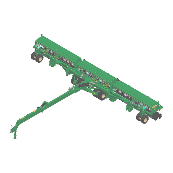
Illustrations may show optional equipment not supplied with standard unit, or, as
above, may show 3S-5000HD model where differences are immaterial to
present topic.
ORIGINAL INSTRUCTIONS
© Copyright 2019
Table of Contents
3S-5000/F/HD/HDF
3-Section 50 Foot Folding Drill
Manufacturing, Inc.
www.greatplainsmfg.com
Printed 4/25/19
EN
195-325Q
Advertisement

Subscribe to Our Youtube Channel
Related Manuals for GREAT PLAINS 3S-5000 Series


Summary of Contents for GREAT PLAINS 3S-5000 Series
- Page 1 Table of Contents Pre-Delivery Manual 3S-5000/F/HD/HDF 3-Section 50 Foot Folding Drill Manufacturing, Inc. www.greatplainsmfg.com Read this manual entirely. When you see this symbol, the subsequent instructions and warnings are serious - follow without exception. Your life and the lives of others depend on it! Illustrations may show optional equipment not supplied with standard unit, or, as above, may show 3S-5000HD model where differences are immaterial to present topic.
- Page 2 Table of Contents Table of Contents...
- Page 3 Great Plains Manufacturing, Inc. provides this publication “as is” without warranty of any kind, either expressed or implied. While every precaution has been taken in the preparation of this manual, Great Plains Manufacturing, Inc. assumes no responsibility for errors or omissions. Neither is any liability assumed for damages resulting from the use of the information contained herein.
- Page 4 Table of Contents Table of Contents...
- Page 5 Table of Contents Introduction Great Plains Manufacturing wants you to be satisfied with any new machine delivered by the Great Plains Trucking network. To ease the assembly task and produce a properly working machine, read this entire manual before assembling or setting up new equipment.
- Page 6 3S-5000 Table of Contents Important Safety Information Look for Safety Symbol Avoid High Pressure Fluids Escaping fluid under pressure can penetrate the skin, causing serious injury. Avoid the hazard by relieving pressure before disconnecting The SAFETY ALERT SYMBOL indicates there is a hydraulic lines.
- Page 7 3S-5000 Table of Contents Assembly The following headings are step-by-step instructions for assembling the 3S-5000 drill. Begin with “Tools Required” and “Pre-Assembly Checklist” to make sure you have all necessary parts and equipment. Follow each step to make the job as quick and safe as possible and produce a properly working machine.
- Page 8 3S-5000 Table of Contents Assembly Mount Outside Center Gauge Wheels Refer to Figure 3 1. Jack up frame and support with jack stands or blocks. 2. Mount tires on hubs. Interference and Equipment Damage Risks: Bolt wheels with edge of center dish in toward hub as shown in Figure 3.
- Page 9 3S-5000 Table of Contents Assembly Install Press Wheels Refer to Figure 5 1. Remove inch flange bolt and flange lock from each opener body. 2. Leave pivot bushing components in place and bolt press wheel arm to opener with inch flange bolt...
- Page 10 3S-5000 Table of Contents Assembly Install Wing Walkboards and Steps There are two walkboards, one on the back of each wing seed box. The walkboards themselves are identical for each section. The way they install varies by section. Bolts for walkboards are shipped in a bag in one of the drill boxes.
- Page 11 3S-5000 Table of Contents Assembly Refer to Figure 10 5. Position the bottom plate under the walkboard and inside the top mount . Loosely hold it in place with the washers and nuts 6. Select two sets of: 802-017C HHCS 3/8-16X1 GR5 804-013C WASHER LOCK SPRING 3/8 PLT 803-068C NUT HEX FLANGE 3/8-16 PLT 7.
- Page 12 3S-5000 Table of Contents Assembly Installing Reflectors and Decals WARNING Decals are shipped in a bag in one of the drill boxes. To avoid serious injury or death: Note: To install new reflectors and decals: Watch your step when climbing ladder or reflector walking on walkboard.
- Page 13 3S-5000 Table of Contents Assembly Handles and Lights Install Box Handles Refer to Figure 14 On outside ends of drill boxes, bolt handles to boxes. in hex-flange screws and lock nuts. Figure 14 17347 Box Handle Install Warning Lights Refer to Figure 15 1.
- Page 14 3S-5000 Table of Contents Assembly Markers Refer to Figure 17 Markers are not factory-installed, due to vertical clearance requirements during shipment. An installation manual is provided. Consult the drill’s Operator manual for setting initial marker extension length, and the latest information on chain length and stop bolt adjustment.
-
Page 15: Setup
3S-5000 Table of Contents Setup Hitching Tractor to Drill You may be severely injured or killed by being crushed between the tractor and drill. Do not stand or place any part of your body between drill and moving tractor. Stop tractor engine and set park brake before installing the hitch pin. -
Page 16: Refer To Figure 20
Refer to Figure 20 Great Plains hydraulic hoses have color coded handle grips to help you hookup hoses to your tractor outlets. Hoses that go to the same remote valve are marked with the same color. - Page 17 3S-5000 Table of Contents Setup Bleeding Hydraulics To function properly, the hydraulics must be free of air. If hydraulics have not been bled, they will operate with jerky, uneven motions and could cause wings to drop rapidly during folding or unfolding. If hydraulics were not bled during initial implement setup or if you replace a part in hydraulic system during the life of the drill, complete the following procedures.
-
Page 18: Refer To Figure 21
3S-5000 Table of Contents Setup Bleeding Opener Lift Hydraulics Refer to Figure 21 1. Check hydraulic fluid level in tractor reservoir and fill to 6. Slowly supply oil to top side of pressure-control valves proper level. Add fluid to system as needed. System until oil begins to appear at a loosened hose fitting. - Page 19 3S-5000 Table of Contents Setup Bleeding Fold & Jack Hydraulics Refer to Figure 22 1. Check hydraulic fluid level in tractor reservoir and fill to 6. With cylinders completely retracted, loosen base end proper level. Add fluid to system as needed. hose fittings at elbow on lower fold cylinders.
- Page 20 3S-5000 Table of Contents Setup Bleeding Transport Lift Hydraulics Crushing Hazard: The hydraulics could fail, causing the openers to fall and crush you. To prevent serious injury or death, always secure cylinder lock channels over extended transport-lift cylinders before working under openers. Refer to Figure 23 1.
- Page 21 3S-5000 Table of Contents Setup Folding Crushing Hazard: Bystanders could be crushed between the folding drill boxes and the drill tongue. To avoid serious injury or death, keep all bystanders well away during drill operation. 1. Park tractor and drill on level ground with tractor transmission in park.
- Page 22 3S-5000 Table of Contents Setup Unfolding Crushing Hazard: Bystanders could be crushed between the folding drill boxes and the drill tongue. To avoid serious injury or death, keep all bystanders well away during drill operation. 1. Park tractor and drill on level ground with tractor transmission in park.
- Page 23 3S-5000 Table of Contents Setup Leveling the Drill Center Box Frame Leveling Refer to Figure 32 1. Park the drill on a clean level surface. 2. Raise the openers and lock them up. Raising openers while machine is unfolded and/or unhitched can result in damage to the machine and create unsafe working conditions.
- Page 24 3S-5000 Table of Contents Setup Frame Adjustments Refer to Figure 34 Toolbar Height Adjustment Truss Tube Tension Toolbar height is factory set and normally will not require The truss tubes help hold the center tool bar adjustment. If the toolbar is visibly not level, spacer perpendicular to the tongue and straight under load.
- Page 25 3S-5000 Table of Contents Setup Wing Box Alignment Refer to Figure 35 1. Place a block ahead of the wing gauge wheels. 2. Pull forward against blocks to rock wing frames back. Pull forward until stop bolts are firmly against tool- bars.
- Page 26 3S-5000 Table of Contents Setup Align Transfer Drive Shaft Refer to Figure 38 After wing boxes are properly aligned, the transfer drive 1. Place a 4x4 or similar sized block ahead of the wing shaft must be aligned so the pair of break-away jaws are gauge wheels and pull forward or push wing box fully engaged and are concentric.
- Page 27 3S-5000 Table of Contents Setup Refer to Figure 39 3. To align the clutch jaws from front to rear, loosen the 4. To adjust clutch jaws for full jaw contact, loosen the two 1/2 inch carriage bolts and slide breakaway inch carriage bolts and slide breakaway clutch...
-
Page 28: Table Of Contents
3S-5000 Table of Contents Setup Install Final Accessories Acremeter Installation Refer to Figure 41 The acremeter is supplied from the factory in a separate carton, to minimize risk of shipping damage. To install the acremeter, please refer to the appropriate manual for the acremeter your machine has. - Page 29 3S-5000 Table of Contents Setup Two Outlet Hydraulic Kit Refer to Figure 43 Manual Number Installation Kit 195-308M Two Outlet Hydraulic To operate all drill functions, the standard 3S-5000 requires a tractor with three remote valves. Tractors with two remote valves can be used with the two outlet hydraulic kit.
- Page 30 3S-5000 Table of Contents Setup Markers Refer to Figure 46 Manual Number Installation Kit 113-728M Hydraulic Markers Markers are not factory-installed, due to vertical clearance requirements during shipment. installation manual is provided. Consult the drill’s operator manual for setting initial marker extension length, and the latest information on chain length and stop bolt adjustment.
- Page 31 3S-5000 Table of Contents Setup Open Center Conversion Kit Refer to Figure 48 Manual Number Installation Kit 194-149M Open Center Conversion The standard 3S-5000 drill is compatible with tractors having “active” or “closed center” hydraulic systems. For use with “non-active” or “closed center” tractors, a conversion kit is available.
- Page 32 3S-5000 Table of Contents Setup Torque Values Chart Bolt Head Identification Bolt Head Identification Bolt Bolt 10.9 Size Size Grade 2 Grade 5 Grade 8 Class 5.8 Class 8.8 Class 10.9 ft-lb ft-lb ft-lb ft-lb ft-lb in-tpi ft-lb mm x pitch M 5 X 0.8 M 6 X 1 M 8 X 1.25...
- Page 33 Table of Contents Table of Contents...
- Page 34 Great Plains, Mfg. 1525 E. North St. P.O. Box 5060 Salina, KS 67402...
Need help?
Do you have a question about the 3S-5000 Series and is the answer not in the manual?
Questions and answers