HIKVISION DS-KD8003-IME1 User Manual
Video intercom module door station
Hide thumbs
Also See for DS-KD8003-IME1:
- Quick start manual (67 pages) ,
- Manual (6 pages) ,
- User manual (21 pages)
Table of Contents
Advertisement
Advertisement
Table of Contents

Related Manuals for HIKVISION DS-KD8003-IME1


Summary of Contents for HIKVISION DS-KD8003-IME1
- Page 1 Video Intercom Module Door Station User Manual...
- Page 2 Trademarks and other Hikvision marks are the property of Hikvision and are registered trademarks or the subject of applications for the same by Hikvision and/or its affiliates. Other trademarks mentioned in this manual are the properties of their respective owners. No right of license is given to use such trademarks without express permission.
- Page 3 Video Intercom Module Door Station·User Manual TO THE MAXIMUM EXTENT PERMITTED BY APPLICABLE LAW, IN NO EVENT WILL HIKVISION, ITS DIRECTORS, OFFICERS, EMPLOYEES, OR AGENTS BE LIABLE TO YOU FOR ANY SPECIAL, CONSEQUENTIAL, INCIDENTAL, OR INDIRECT DAMAGES, INCLUDING, AMONG OTHERS, DAMAGES...
- Page 4 Video Intercom Module Door Station·User Manual Regulatory Information FCC Information Please take attention that changes or modification not expressly approved by the party responsible for compliance could void the user’s authority to operate the equipment. FCC compliance: This equipment has been tested and found to comply with the limits for a Class B digital device, pursuant to part 15 of the FCC Rules.
- Page 5 Video Intercom Module Door Station·User Manual 2006/66/EC (battery directive): This product contains a battery that cannot be disposed of as unsorted municipal waste in the European Union. See the product documentation for specific battery information. The battery is marked with this symbol, which may include lettering to indicate cadmium (Cd), lead (Pb), or mercury (Hg).
- Page 6 Video Intercom Module Door Station·User Manual Safety Instruction These instructions are intended to ensure that user can use the product correctly to avoid danger or property loss. The precaution measure is divided into Warnings and Cautions: Warnings: Neglecting any of the warnings may cause serious injury or death. Cautions: Neglecting any of the cautions may cause injury or equipment damage.
- Page 7 Video Intercom Module Door Station·User Manual Cautions Do not drop the device or subject it to physical shock, and do not expose it to high electromagnetism radiation. Avoid the equipment installation on vibrations surface or places subject to shock (ignorance can cause equipment damage). ...
-
Page 8: Table Of Contents
Video Intercom Module Door Station·User Manual Table of Contents 1 Overview ...................... 1 1.1 Introduction ......................1 1.2 Main Features ......................1 1.3 Typical Application ....................2 2 Appearance ....................3 2.1 Main Unit ......................... 3 2.2 Nametag Module ..................... 4 2.3 Keypad Module ...................... - Page 9 Video Intercom Module Door Station·User Manual 5.2 Edit Network Parameters ..................56 5.3 Add Device ......................57 5.4 Reset Password ...................... 59 5.5 Configure System Parameters ................61 5.5.1 Device Information ..................61 5.5.2 General ......................61 5.5.3 Time ........................ 61 5.5.4 System Maintenance ..................62 5.5.5 User .........................
-
Page 10: Overview
Video Intercom Module Door Station·User Manual 1 Overview 1.1 Introduction The video intercom module door station can realize functions such as video intercom, resident-to-resident video call to provide a complete smart community video intercom solution. The video intercom module door station is mainly applied to situations such as community, villa, and official buildings. -
Page 11: Typical Application
Video Intercom Module Door Station·User Manual 1.3 Typical Application Figure 1-1 Typical Application... -
Page 12: Appearance
Video Intercom Module Door Station·User Manual 2 Appearance 2.1 Main Unit Figure 2-1 Main Unit Appearance Table 2-1 Appearance Description Description Microphone Low Illumination IR Supplement Light Built-in Camera Loudspeaker Call Button Nametag TAMPER Network Interface Module-connecting Interface(output) Terminals Nametag area supports insert customized name card. The suggested card size is: 58 (L) x 11.7(W) mm. -
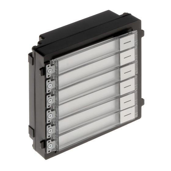
Page 13: Nametag Module
Video Intercom Module Door Station·User Manual 2.2 Nametag Module Figure 2-2 Nametag Module Appearance Table 2-2 Appearance Description Description Call Button Nametag Module-connecting Interface(output) Module-connecting Interface(input) Debug Port Nametag area supports insert customized name card. The suggested card size is: 58 (L) x 11.7(W) mm. -
Page 14: Keypad Module
Video Intercom Module Door Station·User Manual 2.3 Keypad Module Figure 2-3 Keypad Module Appearance Table 2-3 Appearance Description Description Button Module-connecting Interface(output) Module-connecting Interface(input) Debug Port 2.4 Indicator Module Figure 2-4 Keypad Module Appearance... -
Page 15: Card Reader Module
Video Intercom Module Door Station·User Manual Table 2-4 Appearance Description Description Indicator1(Solid yellow during calling) Indicator2(Solid white during two-way audio) Indicator3(Solid blue when door is open) Module-connecting Interface(output) Module-connecting Interface(input) Debug Port 2.5 Card Reader Module Figure 2-5 Card Reader Module Appearance Table 2-5 Appearance Description Description Card Reading Area... -
Page 16: Blank Module
Video Intercom Module Door Station·User Manual 2.6 Blank Module Figure 2-6 Blank Module Appearance Table 2-6 Appearance Description Description Supports to insert customized information card... -
Page 17: Terminal And Wiring
Video Intercom Module Door Station·User Manual 3 Terminal and Wiring 3.1 Terminal Description 3.1.1 Main Unit Figure 3-1 Terminals and Interfaces Table 3-1 Descriptions of Terminals and Interfaces Interface Description Door Lock Relay Output (NC) Door Lock Relay Output (NO) Common Interface Door Lock Relay Output (NC) Door Lock Relay Output (NO) -
Page 18: Sub Module
Video Intercom Module Door Station·User Manual Interface Description AIN4 For the access of Exit Button 2 485- 485+ Module-connecting Interface 12V OUT PoE Network Interface(Supports IEEE 802.3af/at-Compliant Devices) 3.1.2 Sub Module All the modules except the main work as the sub module. The sub module’s interfaces and terminals as below: Figure 3-2 Terminals and Interfaces Table 3-2 Descriptions of Terminals and Interfaces... -
Page 19: Wiring Description
Video Intercom Module Door Station·User Manual 3.2 Wiring Description 3.2.3 Door Lock Wiring Figure 3-3 Door Lock Wiring Terminal NC1/COM is set as default for accessing magnetic lock/electric bolt; terminal NO2/COM is set as default for accessing electric strike. ... -
Page 20: Door Magnetic Wiring
Video Intercom Module Door Station·User Manual 3.2.4 Door Magnetic Wiring Figure 3-4 Door Magnetic Wiring AIN1 and AIN2 are defaulted to connect door magnetic. Door magnetic connected to AIN1 detects status of the lock that connected to NC1/NO1; Door magnetic connected to AIN2 detects the status of the lock connected to NC2/NO2. - Page 21 Video Intercom Module Door Station·User Manual AIN3 and AIN4 are set as default for connecting exit button. Exit button connected to AIN3 opens the lock connected to NC1/NO1; Exit button connected to AIN4 controls the lock that connected to NC2/NO2.
-
Page 22: Installation
Video Intercom Module Door Station·User Manual 4 Installation Before you start: Make sure the device in the package is in good condition and all the assembly parts are included. Set the sub module address before start the installation steps. ... -
Page 23: One-Module Installation
Video Intercom Module Door Station·User Manual 2. Set the sub module address according to the DIP rules, and install the rubber cover back. Digit 1, 2, 3, 4 are used to coding the sub module address; Digit 5, 6, 7, 8 are reserved. ... -
Page 24: One-Module Surface Mounting
Video Intercom Module Door Station·User Manual The dimension of one module mounting frame is: 117(L)×107(W)×32.7(D) mm. The dimensions above are for reference only. The actual size can be slightly different from the theoretical dimension. 4.2.2 One-Module Surface Mounting Steps: 1. - Page 25 Video Intercom Module Door Station·User Manual Figure 4-4 Fix the Mounting Frame The mounting frame should be placed exactly as below for this step. The tamper plate should be at the low-right. 5. Connect the cables to the corresponding interfaces of the main unit and insert it into the frame.
-
Page 26: One-Module Flush Mounting
Video Intercom Module Door Station·User Manual Figure 4-5 Insert the Main unit 6. Use the hexagon wrench in the package fix the cover onto the frame. Figure 4-6 Fix the Cover 4.2.3 One-Module Flush Mounting Steps:... - Page 27 Video Intercom Module Door Station·User Manual 1. Paste the installation Sticker A onto the wall. Make sure the sticker is placed leveled via measuring with the gradienter. 2. Cave the installation hole along the solid line on Sticker A. The suggested dimension of installation hole is 121(L)×111(W)×33(D) mm. Figure 4-7 Cave the Installation Hole 3.
- Page 28 Video Intercom Module Door Station·User Manual Figure 4-9 Install Mounting Frame The mounting frame should be placed exactly as below for this step. The tamper plate should be at the low-right. 7. Fill and level up the gap between the frame and wall with concrete. Remove the locating plates after concrete is dry.
- Page 29 Video Intercom Module Door Station·User Manual Figure 4-10 Insert the Main unit 9. Use the hexagon wrench in the package fix the cover onto the frame. Figure 4-11 Fix the Cover...
-
Page 30: Two-Module Installation
Video Intercom Module Door Station·User Manual 4.3 Two-Module Installation 4.3.1 Installation Accessory Description Figure 4-12 Front and Side View The dimension of two-module mounting frame is: 219(L)×107 (W)×32.7(D) mm. The dimensions above are for reference only. The actual size can be slightly different from the theoretical dimension. - Page 31 Video Intercom Module Door Station·User Manual Figure 4-13 Chisel Screw Hole 3. Remove the sticker and insert the expansion sleeves into the screw holes. 4. Fix the mounting frame onto the wall with 4 expansion bolts. Figure 4-14 Fix the Mounting Frame...
- Page 32 Video Intercom Module Door Station·User Manual The mounting frame should be placed exactly as below for this step. The tamper plate should be at the low right of the first grid. 5. Thread the module-connecting line across the thread hole of the frame. Pass the main unit connecting lines across the thread hole to the upper grid.
- Page 33 Video Intercom Module Door Station·User Manual Figure 4-16 Line Connection Effect Picture 7. Insert the modules in to the frame after wiring. Main unit must be placed in the top grid. Figure 4-17 Insert the Modules 8. Use the hexagon wrench in the package fix the cover onto the frame.
-
Page 34: Two-Module Flush Mounting
Video Intercom Module Door Station·User Manual Figure 4-18 Fix the Cover 4.3.3 Two-Module Flush Mounting Steps: 1. Paste the installation Sticker A onto the wall. Make sure the sticker is placed leveled via measuring with the gradienter. 2. Cave the installation hole along the solid line on Sticker A. The suggested dimension of installation hole is 223(L)×111(W)×33(D) mm. - Page 35 Video Intercom Module Door Station·User Manual The suggested size of screw hole is 6 (diameter) × 25 (depth) mm. The suggested length of cables left outside is 270 mm. 4. Remove the sticker and insert the expansion sleeves into the screw holes. 5.
- Page 36 Video Intercom Module Door Station·User Manual 7. Fill and level up the gap between the frame and wall with concrete. Remove the locating plates after the concrete is dry. 8. Thread the module-connecting line across the thread hole of the frame. Pass the main unit connecting lines across the thread hole to the upper grid.
- Page 37 Video Intercom Module Door Station·User Manual Organize the line with cable tie in the package. The suggested line connection picture as below. Figure 4-23 Line Connection Effect Picture 10. Insert the modules in to the frame after wiring. Main unit must be placed in the top grid.
-
Page 38: Three-Module Installation
Video Intercom Module Door Station·User Manual Figure 4-25 Fix the Cover 4.4 Three-Module Installation 4.4.1 Installation Accessory Description Figure 4-26 Front and Side View... -
Page 39: Three-Module Surface Mounting
Video Intercom Module Door Station·User Manual The dimension of two-module mounting frame is: 320.8(L)×107 (W)×32.7(D) mm. The dimensions above are for reference only. The actual size can be slightly different from the theoretical dimension. 4.4.2 Three-Module Surface Mounting Steps: 1. - Page 40 Video Intercom Module Door Station·User Manual Figure 4-28 Fix the Mounting Frame The mounting frame should be placed exactly as below for this step. The tamper plate should be at the low right of the first grid. 5. Thread the module-connecting lines across the thread holes of the frame. Pass the main unit connecting lines across the thread hole to the top grid.
- Page 41 Video Intercom Module Door Station·User Manual Figure 4-29 Placement of Lines 6. Connect the cables and module-connecting line 1 to the corresponding interfaces of the main unit, then place the main unit into the upper grid. Connect the other end of the module-connecting line1 to the input interface of the sub module.
- Page 42 Video Intercom Module Door Station·User Manual Figure 4-30 Line Connection Effect Picture 7. Insert the modules in to the frame after wiring. Main unit must be placed in the top grid. Figure 4-31 Insert the Modules 8. Use the hexagon wrench in the package fix the cover onto the frame.
-
Page 43: Three-Module Flush Mounting
Video Intercom Module Door Station·User Manual Figure 4-32 Fix the Cover 4.4.3 Three-Module Flush Mounting Steps: 1. Paste the installation Sticker A onto the wall. Make sure the sticker is placed leveled via measuring with the gradienter. 2. Cave the installation hole along the solid line on Sticker A. The suggested dimension of installation hole is 323(L)×111(W)×33(D) mm. - Page 44 Video Intercom Module Door Station·User Manual 3. Pull out the cables, place the installation Sticker 1 into the hole, chisel 4 screw holes accordingly. The suggested size of screw hole is 6 (diameter) × 25 (depth) mm. The suggested length of cables left outside is 270 mm. 4.
- Page 45 Video Intercom Module Door Station·User Manual 7. Fill and level up the gap between the frame and wall with concrete. Remove the locating plates after the concrete is try. 8. Thread the module-connecting lines across the thread holes of the frame. Pass the main unit connecting lines across the thread hole to the upper grid.
- Page 46 Video Intercom Module Door Station·User Manual Figure 4-36 Placement of Lines 9. Connect the cables and module-connecting line 1 to the corresponding interfaces of the main unit, then place the main unit into the upper grid. Connect the other end of the module-connecting line1 to the input interface of the sub module.
- Page 47 Video Intercom Module Door Station·User Manual Figure 4-37 Line Connection Effect Picture 10. Insert the modules in to the frame after wiring. Main unit must be placed in the top grid. Figure 4-38 Insert the Modules 11. Use the hexagon wrench in the package fix the cover onto the frame.
- Page 48 Video Intercom Module Door Station·User Manual Figure 4-39 Fix the Cover...
-
Page 49: More-Than-Three Module Installation
Video Intercom Module Door Station·User Manual 4.5 More-than-Three Module Installation 4.5.1 Installation Accessory Description Figure 4-40 Front and Side View It takes two three-module mounting frames. The dimension of three-module mounting frame is: 320.8(L)×107 (W)×32.7(D) mm. The dimensions above are for reference only. The actual size can be slightly different from the theoretical dimension. - Page 50 Video Intercom Module Door Station·User Manual The suggested length of cables left outside is 270 mm. 3. Pull out the cable through the cable hole of the left sticker. Figure 4-41 Chisel Screw Hole 4. Remove the stickers and insert the expansion sleeves into the screw holes. 5.
- Page 51 Video Intercom Module Door Station·User Manual There are 6 module-connecting lines in the package: 190 mm *4 and 400 mm*2. Take the 400 mm one for this step. The green-yellow line in the package is for grounding. 6. Fix the mounting frame onto the wall with 8 expansion bolts. Figure 4-43 Fix the Mounting Frame The mounting frame should be placed exactly as below for this step.
- Page 52 Video Intercom Module Door Station·User Manual 7. Pass the main unit connecting lines across the thread hole to the top grid of the left frame. Thread the module-connecting line (190 mm) across the thread hole of the frame. The lines should be placed as below:...
- Page 53 Video Intercom Module Door Station·User Manual Figure 4-44 Placement of Lines 8. Connect the cables and module-connecting line 1 to the corresponding interfaces of the main unit, then place the main unit into the upper grid. Connect the other end of the module-connecting line1 to the input interface of the sub module.
- Page 54 Video Intercom Module Door Station·User Manual Figure 4-46 Insert the Modules 10. Pull the grounding line out and fixed its two end to the screw on the cover. Figure 4-47 Connect the Grounding Line to the Cover 11. Use the hexagon wrench in the package fix the cover onto the frame.
-
Page 55: More-Than-Four Module Flush Mounting
Video Intercom Module Door Station·User Manual Figure 4-48 Fix the Cover 4.5.3 More-than-Four Module Flush Mounting Steps: 1. Paste two installation Sticker A onto the wall, align them along the solid line. Make sure the stickers are placed leveled via measuring with the gradienter. 2. - Page 56 Video Intercom Module Door Station·User Manual Figure 4-49 Cave the Installation Hole 3. Paste two Sticker 1 inside the installation hole. The gap between two stickers should be 17 mm. Chisel screw holes according to the stickers. The suggested size of hole is 6 (diameter) × 25 (depth) mm.
- Page 57 Video Intercom Module Door Station·User Manual Figure 4-50 Chisel Screw Hole 4. Pull out the cable through the cable hole of the left sticker. The suggested length of cables left outside is 270 mm. 5. Remove the stickers and insert the expansion sleeves into the screw holes. 6.
- Page 58 Video Intercom Module Door Station·User Manual Figure 4-51 Install Locating Plate 7. Thread the module-connecting line (400 mm) and grounding line across the thread hole of both frames. Figure 4-52 Place the Grounding Line and Module-Connecting Line There are 6 module-connecting lines in the package: 190 mm *4 and 400 mm*2. Take the 400 mm one for this step.
- Page 59 Video Intercom Module Door Station·User Manual Figure 4-53 Install Mounting Frames The mounting frame should be placed exactly as below for this step. The tamper plate should be at the low right of the first grid.
- Page 60 Video Intercom Module Door Station·User Manual 9. Fill and level up the gap between the frame and wall with concrete. Remove the locating plates after the concrete is dry. 10. Pass the main unit connecting lines across the thread hole to the top grid of the left frame.
- Page 61 Video Intercom Module Door Station·User Manual Figure 4-55 Line Connection Effect Picture 12. Insert the modules in to the frame after wiring. Main unit must be placed in the top grid on the left.
- Page 62 Video Intercom Module Door Station·User Manual Figure 4-56 Insert the Modules 13. Pull the grounding line out and fixed its two end to the screw on the cover. Figure 4-57 Connect the Grounding Line to the Cover 14. Use the hexagon wrench in the package fix the cover onto the frame.
- Page 63 Video Intercom Module Door Station·User Manual Figure 4-58 Fix the Cover...
-
Page 64: Device Configuration
Video Intercom Module Door Station·User Manual 5 Device Configuration You need to activate device and configure corresponding parameters via iVMS-4200 before use. 5.1 Activate Device You cannot use the door station until you activate it. You can configure and operate the video intercom devices via iVMS-4200. Default parameters of door station are as follows: ... -
Page 65: Edit Network Parameters
Video Intercom Module Door Station·User Manual STRONG PASSWORD RECOMMENDED– We highly recommend you create a strong password of your own choosing (Using a minimum of 8 characters, including at least three of the following categories: upper case letters, lower case letters, numbers, and special characters.) in order to increase the security of your product. -
Page 66: Add Device
Device Management page. 2. Click Device. 3. On the Device Type panel on the right, you can select Hikvision Device to add video intercom devices. 4. The active online devices in the same local subnet with the client software will be displayed on the Online Device area. - Page 67 Video Intercom Module Door Station·User Manual To add online devices to the software, you are required to change the device IP address to the same subnet with your computer first. 5. Select the devices to be added from the list. 6.
-
Page 68: Reset Password
Video Intercom Module Door Station·User Manual Add Multiple Online Devices If you want to add multiple online devices to the client software, click and hold Ctrl key to select multiple devices, and click Add to Client to open the device adding dialog box. In the pop-up message box, enter the user name and password for the devices to be added. - Page 69 Video Intercom Module Door Station·User Manual 1. Click Export to save the device file on your computer. 2. Send the file to our technical engineers. 3. Our technical engineer will send you a file to you. After receiving a file from the technical engineer, select Import File from Key Importing Mode drop-down list and click to import the file.
-
Page 70: Configure System Parameters
Video Intercom Module Door Station·User Manual 5.5 Configure System Parameters In the device list area, select a device and click to enter the remote configuration interface. Click the System button on the remote configuration interface to display the device information: Device Information, General, Time, System Maintenance, User, and so on. Device Information 5.5.1 Click the Device Information button to enter device basic information interface. -
Page 71: System Maintenance
Video Intercom Module Door Station·User Manual 1. Click the Time button to enter the device time settings interface. 2. Select Time Zone or Enable NTP. Time Zone Select a time zone from the drop-down list menu. Click the Synchronization button. ... - Page 72 Video Intercom Module Door Station·User Manual 2. Click Reboot and the system reboot dialog box pops up. Click Yes to reboot the system. 3. Click Restore Default Settings to restore the default parameters. 4. Click Restore All to restore all parameters of device and reset the device to inactive status.
-
Page 73: User
Video Intercom Module Door Station·User Manual 7. Click to select the upgrade file and click Upgrade to remote upgrade the device. The process of remote upgrade will be displayed in the process bar. Figure 5-1 Remote Upgrade Click Restore Default Settings button, all default settings, excluding network parameters, will be restored. -
Page 74: Configure Video Intercom Parameters
Video Intercom Module Door Station·User Manual 3. Enter the new password, and confirm it. 4. Click the Save button to realize the editing of password. The new password and confirm password should be identical. After editing the password of device, click button from the device list, the added device will not be there. -
Page 75: Time Parameters
Video Intercom Module Door Station·User Manual 2. Select the device type from the drop-down list, and set the corresponding information. 3. Click the Save button to enable the device number configuration. For main door station, the serial No. is 0. ... - Page 76 Video Intercom Module Door Station·User Manual Access Control 1. Select the door No.. 2. Set the door-unlocked duration. 3. (Optional) Enable Upload Alarm for Not-Closed Door. 4. Click Save to enable the settings. The door-unlocked duration ranges from 1s to 225s. ...
-
Page 77: Io Input And Output
Video Intercom Module Door Station·User Manual Make sure your door station is in the mode of main door station. Only the main door station support elevator control function. Connection between the door station and the elevator controller supports network interface. Step: 1. -
Page 78: Volume Input And Output
Video Intercom Module Door Station·User Manual For door station, there are 2 I/O Output Terminals. Terminal 1~2 correspond to DOOR interfaces (NO1/COM/NC1; NO2/COM/NC2) of door station. Door 1 is enabled by default. You can enable/disable IO Out according to needs. 5.6.5 Volume Input and Output Step: 1. -
Page 79: Configure Video Intercom Network
Video Intercom Module Door Station·User Manual 2. Click to pop up the configuration interface. 3. Enter the room no. for each call button of the nametag module. 4. Click the Save button to enable the settings. The module address is used to differentiate the sub modules. See 4.1Configure Sub Module Address for detailed configuration instructions. -
Page 80: Linked Devices Network Configuration
Video Intercom Module Door Station·User Manual 2. Enter the local IP address, subnet mask, gateway address, and port No.. 3. Click the Save button to enable the settings. The default port No. is 8000. After editing the local network parameters of device, you should add the devices to the device list again. -
Page 81: Ftp
Video Intercom Module Door Station·User Manual After adding SIP Server Address IP, the video intercom of same community: video intercom between indoor stations of different building, calling indoor station from outer door station and video intercom between management center and indoors. ... -
Page 82: Advanced Settings
Video Intercom Module Door Station·User Manual 7. Select the directory structure and set the separator, naming item, and naming element. 8. Click the Save button to enable the FTP parameters settings. The default port No. is 21. To enable anonymity or not is according to whether the FTP server enables anonymity. -
Page 83: Video & Audio
Video Intercom Module Door Station·User Manual 2. Select the camera No.. 3. Select the video standard (PAL and NTSC can be selected). 4. Set WDR mode (Disable or Enable). 5. Set the brightness, contrast, saturation and sharpness of the video. 6. - Page 84 Video Intercom Module Door Station·User Manual 2. Set the parameters accordingly. 3. Click the Save button to enable the settings. It’s suggested to keep the default settings to ensure the video/image quality.
-
Page 85: Video Intercom Operation
Video Intercom Module Door Station·User Manual 6 Video Intercom Operation 6.1 Video Intercom Operation via Device You can call corresponding resident by pressing the call button on the main unit or on the nametag unit. Make sure you have configured the room No. for the device. 6.2 Video Intercom Operation via iVMS-4200 Purpose: The Video Intercom Management module provides the function of video intercom,... - Page 86 Video Intercom Module Door Station·User Manual Click Answer to answer the call. Or click Hang Up to decline the call. After you answer the call, you will enter the In Call window. Click to adjust the volume of the loudspeaker. Click to hang up.
-
Page 87: View Live Video Of Door Station
Video Intercom Module Door Station·User Manual Click to adjust the volume of the microphone. For door station, you can click to open the door remotely. One video intercom device can only connect with one client software. The maximum ring duration can be set from 15s to 60s via the Remote Configuration of the video intercom device. -
Page 88: Search Video Intercom Information
Video Intercom Module Door Station·User Manual In the Video Intercom page, click the Call Log tab to enter the Call Log page. All the call logs will display on this page and you can check the log information, e.g., call status, start time, resident’s organization and name, device name and ring or speaking duration. - Page 89 Video Intercom Module Door Station·User Manual Set the search conditions, including call status, device type, start time and end time. Call Status: Click to unfold the drop-down list and select the call status as Dialed, Received or Missed. Or select All to search logs with all statuses. ...
- Page 90 Video Intercom Module Door Station·User Manual Set the search conditions, including unlocking type, device type, start time and end time. Unlocking Type: Click to unfold the drop-down list and select the unlocking type as Unlock by Password, Unlock by Duress, Unlock by Card, Unlock by Resident or Unlock by Center.
- Page 91 UD11560B...