
Related Manuals for Rohde & Schwarz ZPH Series


Summary of Contents for Rohde & Schwarz ZPH Series
- Page 1 ® R&S Cable Rider ZPH Handheld Cable and Antenna Analyzer User Manual (=E9À2) 1321095002...
- Page 2 ® This document describes the following R&S Cable Rider ZPH models and options: ● ® R&S ZPH (1321.1211.02) ● ® R&S ZPH (1321.1211.12) ● ® R&S ZPH-B4, Frequency Extension to 4 GHz (1321.0380.02) ● ® R&S ZPH-B22, Preamplifer (1334.5627.02) ● ®...
- Page 3 Safety Instructions Instrucciones de seguridad Sicherheitshinweise Consignes de sécurité Risk of injury and instrument damage The instrument must be used in an appropriate manner to prevent electric shock, fire, personal injury or instrument damage. Do not open the instrument casing. ●...
- Page 4 Gefahr von Verletzungen und Schäden am Gerät Betreiben Sie das Gerät immer ordnungsgemäß, um elektrischen Schlag, Brand, Verletzungen von Personen oder Geräteschäden zu verhindern. Öffnen Sie das Gerätegehäuse nicht. ● Lesen und beachten Sie die "Grundlegenden Sicherheitshinweise", ● die als gedruckte Broschüre dem Gerät beiliegen. Lesen und beachten Sie die Sicherheitshinweise in den folgenden ●...
- Page 5 Safety instructions for rechargeable lithium ion batteries Risk of serious personal injury or even death. You must fully observe the following instructions in order to avoid serious personal injury ‒ or even death ‒ due to an explosion and/or fire. 1.
- Page 6 Instrucciones de seguridad para baterías recargables de ión litio Posibilidad de lesiones graves que en determinadas circunstancias puede causar la muerte. Tenga en cuenta los siguientes avisos en caso de explosión y/o incendio para impedir lesiones graves en personas que, en determinadas circunstancias, podrían incluso causar la muerte.
- Page 7 Sicherheitshinweise für wiederaufladbare Li-Ion-Batterien Mögliche schwere Verletzungen, unter Umständen mit Todesfolge. Beachten Sie die folgenden Hinweise vollständig, um schwere Verletzungen von Personen - unter Umständen mit Todesfolge - durch Explosion und/oder Brand zu verhindern. 1. Batterien nicht zerlegen, öffnen, zerkleinern oder aus großer Höhe fallen lassen. Bei mechanischer Beschädigung besteht die Gefahr des Austritts von Chemikalien.
- Page 8 Consignes de sécurité pour batteries rechargeables lithium-ion Risque de blessures graves pouvant entraîner la mort. Respecter intégralement les consignes ci-dessous afin d'éliminer tout risque de blessures graves voire mortelles par suite d'explosion et/ou d'incendie. 1. Ne pas démonter, ouvrir ou découper les batteries ni les faire tomber d'une hauteur importante.
- Page 9 Customer Support Technical support – where and when you need it For quick, expert help with any Rohde & Schwarz equipment, contact one of our Customer Support Centers. A team of highly qualified engineers provides telephone support and will work with you to find a solution to your query on any aspect of the operation, programming or applications of Rohde &...
-
Page 10: Table Of Contents
® Contents R&S Cable Rider ZPH Contents 1 Preface....................13 Documentation Overview................... 13 Conventions Used in the Documentation..............14 1.2.1 Typographical Conventions...................14 1.2.2 Conventions for Procedure Descriptions...............14 1.2.3 Other Conventions......................15 2 Welcome to the R&S Cable Rider ZPH..........16 3 Getting Started..................17 Preparing for Use...................... - Page 11 ® Contents R&S Cable Rider ZPH 4.2.6 Configuring the Display....................50 4.2.7 Configuring the Audio Output..................52 4.2.8 Configuring Power Supply.....................53 4.2.9 Internal Alignment......................54 4.2.10 Performing Default Calibration..................56 4.2.11 Configuring Calibration Kit Model..................57 4.2.12 Resetting the R&S Cable Rider ZPH................58 Connecting the R&S Cable Rider ZPH to a PC............59 4.3.1 LAN Connection......................
- Page 12 ® Contents R&S Cable Rider ZPH 5.1.7 Hide or Unhide Measurement Result View Display............92 5.1.8 Preview Screenshot...................... 93 5.1.9 Skip Wizard Measurement.................... 93 On-screen Keyboard....................94 Front Panel Keys......................95 5.3.1 POWER Key......................... 95 5.3.2 Screenshot Key......................95 5.3.3 Softkey.......................... 95 5.3.4 System Keys......................... 95 5.3.5 Function Keys.......................
- Page 13 ® Contents R&S Cable Rider ZPH 7.1.6 Phase Measurement....................136 7.1.7 Calibrating Measurements..................137 Configuring Cable and Antenna Tests..............143 7.2.1 Selecting the Cable Mode................... 143 7.2.2 Configuring the Horizontal Axis...................146 7.2.3 Configuring the Vertical Axis..................150 7.2.4 Configuring the Tracking Generator................152 7.2.5 Setting the Measurement Bandwidth................
- Page 14 ® Contents R&S Cable Rider ZPH 8.2.7 Working with Traces....................229 8.2.8 Using Markers......................234 8.2.9 Using Display Lines.....................245 8.2.10 Using Limit Lines......................245 Working with Channel Tables.................. 248 Using Transducer Factors..................249 8.4.1 Unit for Measurements with Transducers..............251 8.4.2 Setting the Reference Level..................252 8.4.3 Frequency Range of Transducer.................252 8.4.4...
- Page 15 ® Contents R&S Cable Rider ZPH 12.1.3 Performing and Configuring Measurements............... 280 12.2 Digital Demodulation....................284 12.2.1 Measurement Configuration..................287 12.2.2 Frequency Configuration.....................290 12.2.3 Amplitude Configuration....................291 12.2.4 Sweep and Trigger Configuration................291 13 Interference Analyzer.................293 13.1 Interference Analysis....................293 13.2 Signal Strength Mapping..................294 13.3 Working with Maps....................294 13.3.1...
- Page 16 ® Contents R&S Cable Rider ZPH 14.4.3 Structure of a Program Message................334 14.4.4 Responses to Queries....................335 14.5 Command Sequence and Command Synchronization..........336 14.6 Remote Control - Commands.................. 336 14.6.1 Common Commands....................338 14.6.2 Remote Commands of the Cable and Antenna Analyzer........... 341 14.6.3 Remote Commands of the Spectrum Analyzer............387 14.6.4...
- Page 17 ® Contents R&S Cable Rider ZPH 15.3.2 Frequency Parameters....................565 15.3.3 BW Parameters......................566 15.3.4 SCALE Parameters.....................567 15.3.5 Sweep Configuration....................568 15.3.6 Limits Line Parameters....................569 15.3.7 Trace Parameters......................569 15.3.8 Marker Parameters..................... 569 15.4 Functions of the Modulation Analysis..............570 15.4.1 Analog Demodulation Measurements................. 570 15.4.2 Digital Demodulation Measurements................
- Page 18 ® Contents R&S Cable Rider ZPH 15.7.6 TRACE Parameters....................590 15.7.7 MARKER Parameters....................591 15.7.8 CAL Parameters......................593 16 Appendix.....................594 16.1 How a Spectrum Analyzer Works................594 List of Commands................599 Index....................610 User Manual 1321.0950.02 ─ 07...
- Page 19 ® Contents R&S Cable Rider ZPH User Manual 1321.0950.02 ─ 07...
-
Page 20: Preface
® Preface R&S Cable Rider ZPH Documentation Overview 1 Preface 1.1 Documentation Overview This section provides an overview of the R&S Cable Rider ZPH user documentation. You find it on the product page at: http://www.rohde-schwarz.com/product/zph.html > "Downloads" Getting started manual Introduces the R&S Cable Rider ZPH and describes how to set up and start working with the product. -
Page 21: Conventions Used In The Documentation
® Preface R&S Cable Rider ZPH Conventions Used in the Documentation The open source acknowledgment document provides verbatim license texts of the used open source software. http://www.rohde-schwarz.com/product/zph.html > "Downloads" > "Firmware". Application notes, application cards, white papers, etc. These documents contain information about possible applications and background information on various topics, see www.rohde-schwarz.com/appnotes. -
Page 22: Other Conventions
® Preface R&S Cable Rider ZPH Conventions Used in the Documentation is described. The alternative procedure using the keys on the instrument or the on- screen keyboard is only described if it deviates from the standard operating proce- dures. The term "select" may refer to any of the described methods, i.e. using a finger on the touchscreen or a key on the instrument or on a keyboard. -
Page 23: Welcome To The R&S Cable Rider Zph
® Welcome to the R&S Cable Rider ZPH R&S Cable Rider ZPH 2 Welcome to the R&S Cable Rider ZPH The R&S Cable Rider ZPH is a new generation Rohde & Schwarz cable and antenna analyzer developed to meet demanding customer requirements. Offering touchscreen input, the analyzer enhances user experience in making measurements fast and easy. -
Page 24: Getting Started
® Getting Started R&S Cable Rider ZPH Preparing for Use 3 Getting Started The following chapters are identical to those in the printed R&S Cable Rider ZPH Get- ting Started manual. ● Preparing for Use....................17 ● Instrument Tour....................... 25 3.1 Preparing for Use 3.1.1 Putting into Operation This chapter describes the basic steps to be taken when setting up the R&S Cable... - Page 25 ® Getting Started R&S Cable Rider ZPH Preparing for Use Risk of electrostatic discharge (ESD) Electrostatic discharge (ESD) can cause damage to the electronic components of the instrument and the device under test (DUT). ESD is most likely to occur when you con- nect or disconnect a DUT or test fixture to the instrument's test ports.
- Page 26 ® Getting Started R&S Cable Rider ZPH Preparing for Use Risk of damage during transportation and shipment Insufficient protection against mechanical and electrostatic effects during transportation and shipment can damage the instrument. ● Always make sure that sufficient mechanical and electrostatic protection is provi- ded.
- Page 27 ® Getting Started R&S Cable Rider ZPH Preparing for Use When laid out horizontally for operation from above, the R&S Cable Rider ZPH is tilted slightly due to the micro-stand at the back. This position provides the optimum viewing angle for the display. To allow easy operation from the front and still be able to read the display, you can swing out the support on the back of the R&S Cable Rider ZPH.
- Page 28 ® Getting Started R&S Cable Rider ZPH Preparing for Use 3.1.1.4 Using the AC Adapter Risk of instrument damage To avoid instrument damage, ● Only use the power supply (R&S HA-Z301, order number 1321.1386.02) included in the delivery. ● Make sure that the AC supply voltage is compatible to the voltage specified on the power supply unit.
- Page 29 ® Getting Started R&S Cable Rider ZPH Preparing for Use 3.1.1.5 Battery Operation The R&S Cable Rider ZPH has a smart battery indicator which displays the battery charging status on the [Power] key as well as the battery icon shown at the top right corner of the display screen.
- Page 30 ® Getting Started R&S Cable Rider ZPH Preparing for Use Figure 3-3: External battery charger 1 = Lithium ion battery R&S HA-Z306 2 = External charger R&S HA-Z303 3 = Power supply unit R&S HA-Z301 or car adapter R&S HA-Z302 Risk of traffic accidents, physical injury and property damage ●...
-
Page 31: Switching The Instrument On And Off
® Getting Started R&S Cable Rider ZPH Preparing for Use ● Do not allow metallic objects to come into contact with the terminals. ● Do not solder directly to the battery. Storage The battery self-discharges while not in use. When storing the battery for an extended period of time, make sure to ●... -
Page 32: Instrument Tour
® Getting Started R&S Cable Rider ZPH Instrument Tour Risk of losing data If a running instrument (without battery) is disconnected directly from the power cord, the instrument loses its current settings. Furthermore, program data may be lost. Press the [Power] key first to shut down the application properly. The following shows the [POWER] key behavior in different operation modes. -
Page 33: Front View
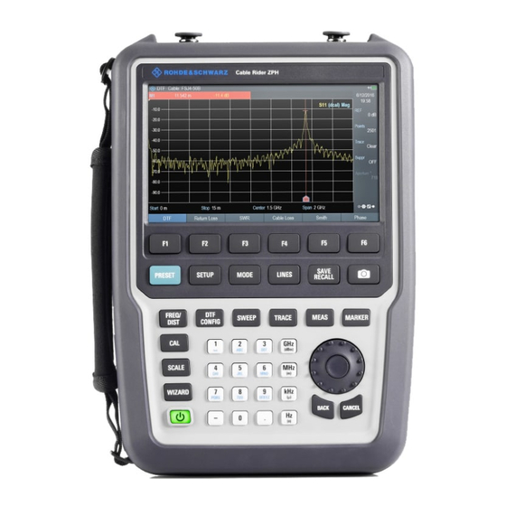
® Getting Started R&S Cable Rider ZPH Instrument Tour 3.2.1 Front View Power meter input / RF Input BNC connector for model .12 Headphone jack for model .12 USB ports Signal source output / Reflection (N-connector) Touch-sensitive screen area 7 = Softkey labels (on display) 8 = Softkey 9 = Systems keys 10 =... -
Page 34: Top View
® Getting Started R&S Cable Rider ZPH Instrument Tour Instrument damage caused by cleaning agents Cleaning agents contain substances that may damage the instrument. For example, cleaning agents that contain a solvent may damage the front panel labeling, plastic parts, or the display. Never use cleaning agents such as solvents (thinners, acetone, etc.), acids, bases, or other substances. - Page 35 ® Getting Started R&S Cable Rider ZPH Instrument Tour Risk of instrument damage To avoid damage to the coupling capacitor, input attenuator or the mixer, the DC input voltage must never exceed the value specified in the data sheet. BNC connector You can connect the BNC connector for various applications.
-
Page 36: Left View
® Getting Started R&S Cable Rider ZPH Instrument Tour RF out / Reflection For model .02, the RF out connector provides a signal source output power at -10.00 dBm nominal. For model .12, the RF out connector provides the following ways to generate a signal source output power at -10.00 dBm nominal. -
Page 37: Right View
® Getting Started R&S Cable Rider ZPH Instrument Tour DC input The R&S Cable Rider ZPH is supplied with power by the AC/DC transformer power supply via the DC connector. You can also use the DC connector to charge the battery. Kensington lock slot A Kensington lock can be anchored to the R&S Cable Rider ZPH housing to secure it to a workstation mechanically. -
Page 38: Display Overview
® Getting Started R&S Cable Rider ZPH Instrument Tour The micro-SD card slot is located behind the battery compartment of the R&S Cable Rider ZPH. Peel open the micro-SD card protective cap to access to the micro-SD card slot. You can use the micro-SD card to store datasets or screenshots. -
Page 39: Basic Operation
® Basic Operation R&S Cable Rider ZPH Screen Layout and Elements 4 Basic Operation The following chapters provide an overview on the measurements that you can per- form with the R&S Cable Rider ZPH. ● Screen Layout and Elements.................. 32 ●... -
Page 40: Title Bar
® Basic Operation R&S Cable Rider ZPH Screen Layout and Elements 8 = Currently selected button 9 = Reference position 10 = Measurement format and calibration status 11 = Upper limit line threshold 12 = Display Line 13 = Measurement trace window 14 = Internal DC bias connecting status (only for model .12) 15 = Trace... -
Page 41: Measurement Trace Window
® Basic Operation R&S Cable Rider ZPH Screen Layout and Elements It displays measurement results of the followings: ● GPS information ● Cable loss result ● Display lines value ● Limit lines result ● Marker values When the marker is selected in the "Measurement result view", an entry box for marker positioning is displayed on the measurement trace window. -
Page 42: Parameter View
® Basic Operation R&S Cable Rider ZPH Screen Layout and Elements Invalid trace indicator is displayed below the S11 result format and calibration sta- tus. For information of result format and calibration status, see Chapter 7.1, "Performing Cable and Antenna Measurements", on page 128 and Chapter 7.1.7.1, "Calibration... - Page 43 ® Basic Operation R&S Cable Rider ZPH Screen Layout and Elements Parameter Description Time & Date Display time and date of the instrument. This is a read-only field. Chapter 4.2.4, "Configuring Date and Time", on page 47 and "Setting the date format" on page 49.
- Page 44 ® Basic Operation R&S Cable Rider ZPH Screen Layout and Elements The "Config Overview" window is divided into six categories: Table 4-2: Corresponding dialog box of Config Overview window "Config Overview" Block Corresponding Dialog Box Description Select "Mode" to configure the desire measurement in cable and antenna (CAT) mode.
- Page 45 ® Basic Operation R&S Cable Rider ZPH Screen Layout and Elements "Config Overview" Block Corresponding Dialog Box Description Select "Cable" to configure the cable model used in the consider- ation of calculation during mea- surement. If "User Mode" is set "No", the preloaded model values are dis- played for the field as read-only parameters for "Frequency",...
-
Page 46: Configuring The R&S Cable Rider Zph
® Basic Operation R&S Cable Rider ZPH Configuring the R&S Cable Rider ZPH 4.2 Configuring the R&S Cable Rider ZPH In the "Instrument Setup" dialog box, the R&S Cable Rider ZPH provides various gen- eral settings that are independent of the operating mode of the R&S Cable Rider ZPH. 1. - Page 47 ® Basic Operation R&S Cable Rider ZPH Configuring the R&S Cable Rider ZPH When this feature is on, the name of the connected accessory is displayed in the "Detected Accessory" field. Configuring the BNC connector BNC connector is only available with model .12. You can use the BNC connectors for various applications.
-
Page 48: Configuring Antennas
® Basic Operation R&S Cable Rider ZPH Configuring the R&S Cable Rider ZPH current level are displayed. See Chapter 4.1.3, "Measurement Trace Window", on page 34. 3. Select the "Internal DC Bias Level (Volt)" item. 4. Enter the desired DC bias voltage. 4.2.2 Configuring Antennas Antennas configuration and calibration are only available with model .12. - Page 49 ® Basic Operation R&S Cable Rider ZPH Configuring the R&S Cable Rider ZPH 2. Select the "HL300", "HE300" or "HE400" "Antenna" menu item. The R&S Cable Rider ZPH enables the selected antenna. Note: The "Auto Accessory Detection" menu item in the "Hardware" section turns off when an antenna is selected.
- Page 50 ® Basic Operation R&S Cable Rider ZPH Configuring the R&S Cable Rider ZPH Assigning functions to the toggle switch The R&S HL300 and HE400 has a toggle switch on its handle that you can assign to one of the following functions: 1.
- Page 51 ® Basic Operation R&S Cable Rider ZPH Configuring the R&S Cable Rider ZPH 3. Select the "Calibrate" softkey. The R&S Cable Rider ZPH starts the calibration. For antenna calibration, it is necessary to move the antenna according to the direc- tion as instructed on the screen.
-
Page 52: Using The Gps Receiver
® Basic Operation R&S Cable Rider ZPH Configuring the R&S Cable Rider ZPH 4. When calibration completes, the R&S Cable Rider ZPH displays a "Calibration Successful" message. The R&S Cable Rider ZPH displays the calibration result. 4.2.3 Using the GPS Receiver R&S Cable Rider ZPH option The R&S ZPH-B10 (order number 1321.0396.02) option is required to activate the internal built-in GPS receiver in model .02 to locate the exact position of the measure-... - Page 53 ® Basic Operation R&S Cable Rider ZPH Configuring the R&S Cable Rider ZPH Location to secure GPS receiver (R&S HA-Z340) Figure 4-2: Location of GPS receiver ● Tighten the knob screw supplied with the GPS receiver to the screw track at the back of R&S Cable Rider ZPH.
-
Page 54: Configuring Date And Time
® Basic Operation R&S Cable Rider ZPH Configuring the R&S Cable Rider ZPH When the "Show GPS Information" item is set on, the R&S Cable Rider ZPH displays the GPS coordinates and number of satellites in the Measurement Result View when sufficient connection is established to the GPS satellites. -
Page 55: Selecting Regional Settings
® Basic Operation R&S Cable Rider ZPH Configuring the R&S Cable Rider ZPH Setting the date 1. In the "Instrument Setup" dialog box, select the "Set Date" item. 2. Enter the date you want with the numeric keys. The sequence depends on the selected date format. - Page 56 ® Basic Operation R&S Cable Rider ZPH Configuring the R&S Cable Rider ZPH Selecting the language The R&S Cable Rider ZPH supports several languages for the user interface. The following is a list of languages that the instrument supports: English Spanish Japanese Russian...
-
Page 57: Configuring The Display
® Basic Operation R&S Cable Rider ZPH Configuring the R&S Cable Rider ZPH 1. In the "Instrument Setup" dialog box, select the "Length Unit" item. A drop- down menu opens to select the length unit. 2. Select the required length unit from the drop-down menu. 4.2.6 Configuring the Display The display setting configures the display characteristics and the touch interface. - Page 58 ® Basic Operation R&S Cable Rider ZPH Configuring the R&S Cable Rider ZPH 3. Confirm the entry with the rotary knob. Adjusting the display color scheme 1. In the "Instrument Setup" dialog box, select the "Display Color Scheme" item. A drop-down menu opens to select the display color scheme. 2.
-
Page 59: Configuring The Audio Output
® Basic Operation R&S Cable Rider ZPH Configuring the R&S Cable Rider ZPH 3. Select "OFF" to deactivate the touchscreen interface. Note: If the touch interface is not activated, the On-screen keyboard is disabled. 4.2.7 Configuring the Audio Output The audio settings control the audio output of the system. Setting the key click volume The key click volume sets the volume of the sound that the R&S Cable Rider ZPH pro- duces when you press a key or select a softkey. -
Page 60: Configuring Power Supply
® Basic Operation R&S Cable Rider ZPH Configuring the R&S Cable Rider ZPH 3. Confirm the entry with the rotary knob. Activating / Deactivating audio alert for power overload In case the R&S Cable Rider ZPH detects an overload at one of its inputs, you can configure it to make a sound. -
Page 61: Internal Alignment
® Basic Operation R&S Cable Rider ZPH Configuring the R&S Cable Rider ZPH Activating / Deactivating audio alert for battery low-level state The R&S Cable Rider ZPH also allows you to turn on an audio signal that indicates that the battery has reached its low-level state. 1. - Page 62 ® Basic Operation R&S Cable Rider ZPH Configuring the R&S Cable Rider ZPH Operating mode ● Frequency clock alignment The frequency clock alignment can only be performed in either CAT or "Spectrum" mode (if R&S ZPH-K1 is installed). If wrong operating mode is detected, a warning message is displayed before align- ment is performed.
-
Page 63: Performing Default Calibration
® Basic Operation R&S Cable Rider ZPH Configuring the R&S Cable Rider ZPH Figure 4-3: Input signal for frequency clock alignment Figure 4-4: Input signal for reference level alignment 4. Connect an input signal of 1.1 GHz, -10dBm at the "RF IN" port for frequency align- ment or 100 MHz, -20 dBm at the "RF IN"... -
Page 64: Configuring Calibration Kit Model
® Basic Operation R&S Cable Rider ZPH Configuring the R&S Cable Rider ZPH The R&S Cable Rider ZPH shows a warning message box. 3. A corresponding dialog box opens for selection. ● Select "Yes" to perform the default calibration. ● Select "No"... -
Page 65: Resetting The R&S Cable Rider Zph
® Basic Operation R&S Cable Rider ZPH Configuring the R&S Cable Rider ZPH 2. Select the calibration kit model that you require. The R&S Cable Rider ZPH loads the selected calibration kit model which is taken in for consideration during the calibration. For more information, see Chapter 7.1.7.2, "Calibration Methods",... -
Page 66: Connecting The R&S Cable Rider Zph To A Pc
® Basic Operation R&S Cable Rider ZPH Connecting the R&S Cable Rider ZPH to a PC tables etc.). Instead, it will reinstall all the datasets that have been available after deliv- ery. Risk of data loss All datasets you have saved are deleted during a factory reset. Calibration data After a factory reset, the R&S Cable Rider ZPH is loaded with the default factory cali- bration data. -
Page 67: Lan Connection
® Basic Operation R&S Cable Rider ZPH Connecting the R&S Cable Rider ZPH to a PC Firewall settings If no connection can be established between the software and the R&S Cable Rider ZPH after successful configuration, check the firewall settings on your PC. ●... - Page 68 ® Basic Operation R&S Cable Rider ZPH Connecting the R&S Cable Rider ZPH to a PC 2. In the "Instrument Settings" dialog box, select the "Subnet Mask" item. 3. Enter the subnet mask of the PC with the numeric keys. After you have matched the subnet mask, you can define the IP address.
- Page 69 ® Basic Operation R&S Cable Rider ZPH Connecting the R&S Cable Rider ZPH to a PC Configuring the R&S InstrumentView software package 1. Start the R&S InstrumentView software. 2. Select the "LAN" tab in the screen layout. 3. Select the "Add" button to create a new network connection. 4.
- Page 70 ® Basic Operation R&S Cable Rider ZPH Connecting the R&S Cable Rider ZPH to a PC The connection is now created and configured. 7. Select the new connection labeled R&S Cable Rider ZPH. 8. Select the "Connect" button to establish the connection. Connecting the R&S Cable Rider ZPH in an existing LAN You can either get the R&S Cable Rider ZPH IP address automatically from the DHCP server or manually assign a fixed address.
-
Page 71: Usb Connection
® Basic Operation R&S Cable Rider ZPH Connecting the R&S Cable Rider ZPH to a PC The R&S Cable Rider ZPH is now allocated an IP address and the subnet mask by the DHCP server. This can take several seconds. The IP address and subnet mask are automatically set in the corresponding input fields and are no longer available for editing. -
Page 72: Managing Options
® Basic Operation R&S Cable Rider ZPH Managing Options 4. Select the "Scan" button to identify the R&S Cable Rider ZPH. 5. Confirm the selection with the "Connect" button. 4.4 Managing Options For special measurement tasks, you can equip the R&S Cable Rider ZPH with various firmware options. -
Page 73: Checking Options
® Basic Operation R&S Cable Rider ZPH Managing Options Figure 4-5: Installed option 3. Select the "Install Option" softkey from the dialog box. The R&S Cable Rider ZPH opens an entry field to enter the option key. 4. Enter in the appropriate option key. 5. -
Page 74: Managing Options With R&S License Manager
® Basic Operation R&S Cable Rider ZPH Managing Options ● "Removed:<option key>": This indicates that a portable license has been removed from the R&S Cable Rider ZPH and is ready to be transferred to another R&S Cable Rider ZPH. 4.4.3 Managing Options with R&S License Manager If you are using the R&S Cable Rider ZPH in a local area network (LAN), you can man- age the firmware options with a web browser (e.g. - Page 75 ® Basic Operation R&S Cable Rider ZPH Managing Options If you already have one or more R&S Cable Rider ZPH equipped with options, you can manage the licenses of these options on the license manager web page. 2. Select the button.
-
Page 76: Identifying Cable Faults
® Basic Operation R&S Cable Rider ZPH Identifying Cable Faults 4.5 Identifying Cable Faults One of the basic measurement tasks for the R&S Cable Rider ZPH is to find cable faults with the distance-to-fault (DTF) measurement. Test setup The test setup requires an R&S Cable Rider ZPH, an RF cable (for example R&S FSH- Z320, order number 1309.6600.00) and a calibration standard (for example R&S FSH- Z28/Z29, order number 1300.7810.03 / 1300.7610.03 or R&S ZN-Z103 order number 3586.9392.00)). - Page 77 ® Basic Operation R&S Cable Rider ZPH Identifying Cable Faults The R&S Cable Rider ZPH switches its operating mode. By default, the R&S Cable Rider ZPH shows the magnitude of the reflection (S11). You can also measure the distance to fault or the cable loss. 3.
- Page 78 ® Basic Operation R&S Cable Rider ZPH Identifying Cable Faults 3. Select the cable model that you require from the list of cables. The R&S Cable Rider ZPH loads the cable model that will be taken in for consider- ation during the distance-to-fault measurement. You can also define new cable models on the R&S Cable Rider ZPH or with the R&S InstrumentView software and then transfer them to the R&S Cable Rider ZPH.
- Page 79 ® Basic Operation R&S Cable Rider ZPH Identifying Cable Faults Calibrating the test setup Using the calibration kit (R&S FSH-Z28 or R&S FSH-Z29), the R&S Cable Rider ZPH performs a "Full 1-Port" calibration over its entire span with 2501 sweep points. Thus, it is not necessary to perform a new calibration after changing the frequency range or cable length.
- Page 80 ® Basic Operation R&S Cable Rider ZPH Identifying Cable Faults In addition to the distance to fault measurement, the R&S Cable Rider ZPH also features a reflection measurement, for example to test impedance matching. Using markers The R&S Cable Rider ZPH uses markers to read out signal levels and frequencies. Markers are always positioned on the trace.
-
Page 81: Measuring Transmissions
® Basic Operation R&S Cable Rider ZPH Measuring Transmissions Using markers, you can determine the magnitude of the cable loss for any particular frequency. 4.6 Measuring Transmissions Measuring transmissions is only available with model .12. This measurement example measures the transmission characteristics of a lowpass fil- ter. - Page 82 ® Basic Operation R&S Cable Rider ZPH Measuring Transmissions 3. Enter 10 MHz as the start frequency. The R&S Cable Rider ZPH adjusts the frequency range according to your settings. 4. Select the "Stop" softkey. The R&S Cable Rider ZPH opens an input field to specify the stop frequency. 5.
-
Page 83: Using The Spectrum Analyzer
® Basic Operation R&S Cable Rider ZPH Using the Spectrum Analyzer 4.7 Using the Spectrum Analyzer R&S Cable Rider ZPH option R&S ZPH-K1, Spectrum analysis (W TG) (1334.5604.02) option is required to operate the R&S Cable Rider ZPH in the spectrum analyzer mode. R&S ZPH-K1 is only available with model .12. - Page 84 ® Basic Operation R&S Cable Rider ZPH Using the Spectrum Analyzer 1. Press the [MODE] key. 2. Select the "Spectrum Analayzer" softkey. The R&S Cable Rider ZPH opens the spectrum analyzer measurement menu. 3. Select the "Spectrum" menu item. The R&S Cable Rider ZPH activates the mode for spectrum analyzer measure- ments.
-
Page 85: Using The Preamplifier
® Basic Operation R&S Cable Rider ZPH Using the Spectrum Analyzer 10. Enter the attenuation you need. The R&S Cable Rider ZPH shows the current attenuation level in the "Parameter View". 4.7.2 Using the Preamplifier The R&S Cable Rider ZPH has an optional preamplifier (R&S ZPH-B22, order number 1334.5627.02) to increase sensitivity. - Page 86 ® Basic Operation R&S Cable Rider ZPH Using the Spectrum Analyzer A signal generator, e.g. R&S SMBV provides the signal source. Test setup Connect the RF output of the signal generator to the RF input of the R&S Cable Rider ZPH.
- Page 87 ® Basic Operation R&S Cable Rider ZPH Using the Spectrum Analyzer Setting the reference level The level at the top of the measurement diagram is called the reference level. To obtain the best dynamic range from the R&S Cable Rider ZPH, you should use its full level range.
-
Page 88: Measuring Harmonics
® Basic Operation R&S Cable Rider ZPH Using the Spectrum Analyzer Measuring the frequency The trace consists of 711 measurement points (frequency points). The marker is always positioned on one of these measurement points. The R&S Cable Rider ZPH calculates the marker frequency from the frequency of the measurement point, the center frequency and the frequency span that have been set. - Page 89 ® Basic Operation R&S Cable Rider ZPH Using the Spectrum Analyzer Test setup Connect the RF output of the signal generator to the RF input of the R&S Cable Rider ZPH. Signal generator settings: ● Frequency: 100 MHz ● Level: -20 dBm Detecting harmonics 1.
-
Page 90: Using A Power Sensor
® Basic Operation R&S Cable Rider ZPH Using a Power Sensor To measure the harmonic ratio, set the marker on the signal and a delta marker on the second harmonic. 9. Press the [MARKER] key. The R&S Cable Rider ZPH sets a marker on the trace maximum. The trace maxi- mum corresponds to the signal. -
Page 91: Measuring The Power With A Power Sensor
® Basic Operation R&S Cable Rider ZPH Using a Power Sensor 4.8.1 Measuring the Power with a Power Sensor For more information about the characteristics of the supported power sensors, refers to their datasheet. Risk of damaging the power sensor Because of high input power, ●... - Page 92 ® Basic Operation R&S Cable Rider ZPH Using a Power Sensor If no power sensor has been connected or is not connected appropriately, the R&S Cable Rider ZPH shows nothing. If there are communication problems between the R&S Cable Rider ZPH and the power sensor, the R&S Cable Rider ZPH displays an error message that indicates a possible cause.
-
Page 93: Measuring Power And Return Loss
® Basic Operation R&S Cable Rider ZPH Using a Power Sensor 2. Enter the frequency of the signal. 3. Confirm the entry with one of the unit keys. The R&S Cable Rider ZPH transfers the new frequency to the power sensor which then corrects the measured power readings. - Page 94 ® Basic Operation R&S Cable Rider ZPH Using a Power Sensor 1 = Directional power sensor R&S FSH-Z14 or Z44 2 = Source 3 = Load 4 = USB binder adaptor (R&S FSH-Z144) 5 = USB port connector Measuring the power 1.
-
Page 95: Saving And Recalling Results And Settings
® Basic Operation R&S Cable Rider ZPH Saving and Recalling Results and Settings 4.9 Saving and Recalling Results and Settings Storage device If both USB flash drive and micro-SD card are connected to the instrument, the USB flash drive takes precedent over SD card as a storage device. If both storage devices are not connected, the internal memory of the instrument is used for storage. -
Page 96: Instrument Functions
® Instrument Functions R&S Cable Rider ZPH Touchscreen Gesture Element 5 Instrument Functions The following chapters provide information about the basic functionality and the user interface of the R&S Cable Rider ZPH. ● Touchscreen Gesture Element................89 ● On-screen Keyboard....................94 ●... -
Page 97: Change Reference Level
® Instrument Functions R&S Cable Rider ZPH Touchscreen Gesture Element 5.1.2 Change Reference Level Swipe up or down vertically in the trace window to adjust the reference level of the spectrum measurement. Alternatively, select the "REF" softkey in the Parameter View to adjust the reference level or press the [SCALE] / [SCALE/AMPT] key on the front panel to display the "Ref Level"... -
Page 98: Add Marker
® Instrument Functions R&S Cable Rider ZPH Touchscreen Gesture Element 5.1.4 Add Marker Double tap in the trace window to create a marker on the spectrum measurement. The marker is placed on the trace where the double tab gesture is performed. Alternatively, press the [MARKER] key on the front panel and select the "New Marker"... -
Page 99: Delete All Markers
® Instrument Functions R&S Cable Rider ZPH Touchscreen Gesture Element 5.1.6 Delete All Markers Draw an "X" on the trace window to delete all markers from the spectrum measure- ment. Alternatively, press the [MARKER] key on the front panel and select the "Delete Marker"... -
Page 100: Preview Screenshot
® Instrument Functions R&S Cable Rider ZPH Touchscreen Gesture Element 5.1.8 Preview Screenshot Swipe horizontally to the left or right direction in the trace window to preview the screenshot. Alternatively, select the "Prev" or "Next" softkey to preview the screenshot. 5.1.9 Skip Wizard Measurement Swipe horizontally to the left direction to skip a wizard measurement. -
Page 101: On-Screen Keyboard
® Instrument Functions R&S Cable Rider ZPH On-screen Keyboard 5.2 On-screen Keyboard The on-screen keyboard is an additional means of interacting with the instrument. It provides convenience of usage with the touchscreen input. Accessing the on-screen keyboard is only available for text-based entry, e.g. save or open a filename. -
Page 102: Front Panel Keys
® Instrument Functions R&S Cable Rider ZPH Front Panel Keys 5.3 Front Panel Keys The following chapter illustrates the function of the front panel keys. 5.3.1 POWER Key The [POWER] key is located on the lower left of the front panel. It starts up and shuts down the instrument. -
Page 103: Function Keys
® Instrument Functions R&S Cable Rider ZPH Front Panel Keys SYSTEM keys Descriptions PRESET Resets the instrument to the default state. SETUP Provides basic instrument configuration functions: ● Date, time, display, audio and regional configuration ● Battery low indicator ● LAN interface ●... - Page 104 ® Instrument Functions R&S Cable Rider ZPH Front Panel Keys FUNCTION keys Descriptions SCALE The [SCALE] or [SCALE/AMPT] key sets the reference level of the measurement. It also performs auto scaling of the reference SCALE/AMPT level. For model .12, the [SCALE/AMPT] key provides the following functions: ●...
-
Page 105: Keypad
® Instrument Functions R&S Cable Rider ZPH Front Panel Keys FUNCTION keys Descriptions MEAS This key provides functionality to select and configure measure- ment such as: ● ● Return Loss ● ● Cable Loss ● Transmission (for model .12) ● Smith ●... -
Page 106: Navigation Controls
® Instrument Functions R&S Cable Rider ZPH Front Panel Keys It contains the following keys: Type of key Description Alphanumeric keys Enter numbers and (special) characters in edit dialog boxes. Decimal point Inserts a decimal point "." at the cursor position. Sign key Changes the sign of a numeric parameter. -
Page 107: Presetting The R&S Cable Rider Zph
® Instrument Functions R&S Cable Rider ZPH Presetting the R&S Cable Rider ZPH The rotary knob has several functions: ● Increments (clockwise direction) or decrements (counter-clockwise direction) the instrument parameters at a defined step width in the case of a numeric entry ●... -
Page 108: Configuring Measurements
® Instrument Functions R&S Cable Rider ZPH Configuring Measurements 4. Select the dataset with the settings you want and press "Load" softkey. 5. In the "User Preferences" dialog box, select the "Preset Mode" item. A drop-down menu opens to select the preset mode. 6. -
Page 109: Working Directory
® Instrument Functions R&S Cable Rider ZPH Saving On Events 2. Select the "Config Overview" softkey. 3. Select one of the dialog boxes and change the settings as you like. Note that the contents of the "Config Overview" dialog box are customized for each operating mode of the R&S Cable Rider ZPH. - Page 110 ® Instrument Functions R&S Cable Rider ZPH Saving On Events 1. Press the [SETUP] key. 2. Select the "User Preference" softkey. 3. Select the "Save On Event" menu item. A drop- down menu to disable or enable the "Save On Event" opens. 4.
- Page 111 ® Instrument Functions R&S Cable Rider ZPH Saving On Events Single sweeps and sweep time It is not possible to save measurement data in single sweep mode because the R&S Cable Rider ZPH only performs one sweep and then stops. The time interval must be longer than the sweep time.
-
Page 112: Taking Screenshots
® Instrument Functions R&S Cable Rider ZPH Taking Screenshots 2. Select the "User Preference" softkey. 3. Select the "Recording Storage" menu item. A drop-down menu to select the recording storage media opens. 4. Select the desired storage media. 5.8 Taking Screenshots You can take and store a screenshot of the current screen anytime with the screenshot key. - Page 113 ® Instrument Functions R&S Cable Rider ZPH Taking Screenshots 4. Select the "Capture Screen Format" items to select the screenshot file format. Previewing screenshots The R&S Cable Rider ZPH provides functionality to preview screenshot. Special touchscreen gesture You can swipe horizontally to the left or right direction to preview the screenshot. Chapter 5.1.8, "Preview Screenshot", on page 93.
-
Page 114: Managing Datasets
® Instrument Functions R&S Cable Rider ZPH Managing Datasets Figure 5-1: Preview screenshot 5.9 Managing Datasets The R&S Cable Rider ZPH provides functionality to manage (e.g. save, restore) data- sets available in its internal memory or an external storage device. Datasets The R&S Cable Rider ZPH supports various types of datasets. - Page 115 ® Instrument Functions R&S Cable Rider ZPH Managing Datasets For more information on working with templates and datasets, refer to the documenta- tion of the R&S InstrumentView software package. Data synchronization The R&S InstrumentView features data synchronization that matches the data availa- ble between the R&S Cable Rider ZPH and the PC.
-
Page 116: Saving Datasets
® Instrument Functions R&S Cable Rider ZPH Managing Datasets ● Saving Datasets....................109 ● Restoring Datasets....................111 ● Deleting Datasets....................113 5.9.1 Saving Datasets The R&S Cable Rider ZPH allows you to save the data that is analyzed at any time. 1. - Page 117 ® Instrument Functions R&S Cable Rider ZPH Managing Datasets The folder structure shows all the available data storage devices. Possible storage devices are the internal memory of the R&S Cable Rider ZPH, micro-SD card or USB flash drive. The default storage device depends on which devices are connected to the R&S Cable Rider ZPH.
-
Page 118: Restoring Datasets
® Instrument Functions R&S Cable Rider ZPH Managing Datasets 5.9.1.2 Renaming Filename If necessary, you can rename files or file directories directly on the R&S Cable Rider ZPH. 1. Press the [SAVE/RECALL] key. 2. Select the "File Manager" softkey. The R&S Cable Rider ZPH opens the file manager. 3. - Page 119 ® Instrument Functions R&S Cable Rider ZPH Managing Datasets 1. Press the [SAVE/RECALL] key. 2. Select the "Recall" softkey. The R&S Cable Rider ZPH opens the "Recall Dataset" dialog box. 3. Select the storage device and file directory you want to load the dataset. The R&S Cable Rider ZPH restores the configuration that the dataset contains.
-
Page 120: Deleting Datasets
® Instrument Functions R&S Cable Rider ZPH Managing Datasets Figure 5-2: Preview dataset 6. Select the "Recall" softkey to load the dataset Alternatively, select the "Exit" softkey to return to the file manager. 5.9.2.2 Loading a Dataset If you find a dataset whose settings you need for your current measurement task, you can load it. -
Page 121: Updating The Firmware
® Instrument Functions R&S Cable Rider ZPH Installing Firmware Options Before deleting, the R&S Cable Rider ZPH shows a warning message that you need to confirm. 6. Select "Yes" to delete the selected files or file directories. The R&S Cable Rider ZPH deletes the selected files or file directories from its memory. -
Page 122: Working With The Measurement Wizard
® Working with the Measurement Wizard R&S Cable Rider ZPH Performing and Configuring Measurements 6 Working with the Measurement Wizard When testing antennas and making measurement which involves complex signals, it is often necessary to perform a sequence of standardized and recurring measurements, often in an environment that is not easily accessible. - Page 123 ® Working with the Measurement Wizard R&S Cable Rider ZPH Performing and Configuring Measurements Load the measurement wizard Now that the measurement set is available on the R&S Cable Rider ZPH, you can per- form the measurement wizard. 1. Press the [Wizard] key. The R&S Cable Rider ZPH opens the wizard dialog box.
- Page 124 ® Working with the Measurement Wizard R&S Cable Rider ZPH Performing and Configuring Measurements Figure 6-2: Measurement setting dialog Table 6-1: Measurement setting parameters Measurement parameters Descriptions General User Name of the person that performs the measurement. Measurement Name of the measurement wizard set. This field is a read- Definition only field that shows the measurement name as defined in the R&S InstrumentView software package.
- Page 125 ® Working with the Measurement Wizard R&S Cable Rider ZPH Performing and Configuring Measurements Measurement parameters Descriptions Comments Comments about the measurement, e.g. the external con- ditions during the measurement. GPS Position Displays the GPS information. See Chapter 4.2.3, "Using the GPS Receiver", on page 45.
- Page 126 ® Working with the Measurement Wizard R&S Cable Rider ZPH Performing and Configuring Measurements Figure 6-3: Measurement specification dialog box 1 = Measurement step in a wizard set 2 = Individual measurement step status Performing a Sequence of Measurements Calibration data The R&S Cable Rider ZPH adds the calibration data of each calibration you perform to a calibration data folder available on its internal memory.
- Page 127 ® Working with the Measurement Wizard R&S Cable Rider ZPH Performing and Configuring Measurements Figure 6-4: Perform wizard measurement dialog box 1 = Image of a measurement step defined in the R&S InstrumentView software package. 2 = Wizard message box 3 = See Table 6-2 1.
- Page 128 ® Working with the Measurement Wizard R&S Cable Rider ZPH Performing and Configuring Measurements Figure 6-5: Measurement wizard dialog – Select the "Next Meas" softkey to proceed to the next measurement step in the measurement sequence. – Select the "Repeat Meas" softkey if the result does not match your expect- ation and you want to validate the result again.
- Page 129 ® Working with the Measurement Wizard R&S Cable Rider ZPH Performing and Configuring Measurements The R&S Cable Rider ZPH skips a single measurement step and continue the subsequent measurement step. Note: Alternatively, you can swipe horizontally to the left direction to skip a wiz- ard measurement.
- Page 130 ® Working with the Measurement Wizard R&S Cable Rider ZPH Performing and Configuring Measurements 4. After all the measurements are completed, the R&S Cable Rider ZPH displays a message "All Measurements Done" in the wizard message box. Select the "Continue" softkey. The R&S Cable Rider ZPH prompts you to save or discard the measurement results.
-
Page 131: Evaluating Results
® Working with the Measurement Wizard R&S Cable Rider ZPH Evaluating Results Softkey Description Finish Wizard Ends the measurement sequence and returns to the "Measurement Wizard" dialog box. The results of the measurements you have already finished are kept in the memory of the R&S Cable Rider ZPH. Ending the sequence is possible when you turn on "Allow to skip measurements and finish wizard sequence"... - Page 132 ® Working with the Measurement Wizard R&S Cable Rider ZPH Evaluating Results The report generator function in R&S InstrumentView allows you to create measure- ment reports for the full measurement set or a selection of dataset only. You can also perform simple tasks like activating or deactivating markers that have been set during the measurement.
-
Page 133: Cable And Antenna Test Mode
® Cable and Antenna Test Mode R&S Cable Rider ZPH 7 Cable and Antenna Test Mode The cable and antenna test (CAT) mode provides functionality to measure cables and antennas of transmission equipment in wireless telecommunication systems. In a perfect system, the signal would arrive at the antenna without any losses and be transmitted with the required power and frequency. - Page 134 ® Cable and Antenna Test Mode R&S Cable Rider ZPH Test setup Signal Source For model .02, an internal fixed signal source at -10 dBm is available. For model .12, a tracking generator is available. See Chapter 7.2.4, "Configuring the Tracking Generator", on page 152.
-
Page 135: Performing Cable And Antenna Measurements
® Cable and Antenna Test Mode R&S Cable Rider ZPH Performing Cable and Antenna Measurements Figure 7-2: Screen layout of cable and antenna test mode 1 = Measurement type 2 = Cable model Title bar Measurement result view 5 = Calibration status line: (S-matrix, calibration status, measurement format) Internal DC bias status: (connector type, voltage, current)) Measurement trace window 8 = Delta marker... -
Page 136: Reflection Measurements
® Cable and Antenna Test Mode R&S Cable Rider ZPH Performing Cable and Antenna Measurements ● Smith Chart......................134 ● Phase Measurement..................... 136 ● Calibrating Measurements..................137 7.1.1 Reflection Measurements The reflection measurement (S11) is a good way to get an idea if the transmission sys- tem works properly. -
Page 137: Distance To Fault Measurements
® Cable and Antenna Test Mode R&S Cable Rider ZPH Performing Cable and Antenna Measurements To draw conclusions about which component is affected and to determine the location of the fault, you need to perform further analysis using other measurements. 7.1.2 Distance to Fault Measurements The distance to fault (DTF) measurement determines the exact location of possible faults in a transmission system. - Page 138 ® Cable and Antenna Test Mode R&S Cable Rider ZPH Performing Cable and Antenna Measurements Figure 7-4: Distance to fault measurement Split screen Using split screen, you can display the DTF measurement in both time and frequency domain. The main DTF measurement is displayed in the upper screen window (time domain) and the reflection measurement is displayed in the lower screen window (fre- quency domain).
-
Page 139: 1-Port Cable Loss Measurement
® Cable and Antenna Test Mode R&S Cable Rider ZPH Performing Cable and Antenna Measurements Figure 7-5: Split screen for DTF measurement 7.1.3 1-Port Cable Loss Measurement (Short + Open) / 2 measurement format When the (Short + Open) / 2 format is selected, additional calibration steps are required to terminate the end of the cable under test with a short and open before the cable loss measurement is performed. -
Page 140: Transmission Measurements
® Cable and Antenna Test Mode R&S Cable Rider ZPH Performing Cable and Antenna Measurements The R&S Cable Rider ZPH displays a submenu to select measurement format. 3. Select "Normal" or "(Short + Open) / 2" menu item. The R&S Cable Rider ZPH evaluates the cable loss over its entire frequency (span) in dB. -
Page 141: Smith Chart
® Cable and Antenna Test Mode R&S Cable Rider ZPH Performing Cable and Antenna Measurements For more information on the test setup and settings, see Chapter 4.6, "Measuring Transmissions", on page 74. 1. Press the [MEAS] key. 2. Select the "Transmission" softkey. The R&S Cable Rider ZPH start the forward transmission measurement over its entire frequency range. - Page 142 ® Cable and Antenna Test Mode R&S Cable Rider ZPH Performing Cable and Antenna Measurements Using markers In addition to the standard marker functionality, the smith chart also features several marker output formats. Marker output format Descriptions "dB Magnitude + Phase" Shows the magnitude (in dB) and the phase at the current marker posi- tion.
-
Page 143: Phase Measurement
® Cable and Antenna Test Mode R&S Cable Rider ZPH Performing Cable and Antenna Measurements By default, the marker position is specified by the marker frequency and complex resistance in Ω. The complex resistance in that case is calculated according to : (real component) + j (imaginary component). -
Page 144: Calibrating Measurements
® Cable and Antenna Test Mode R&S Cable Rider ZPH Performing Cable and Antenna Measurements ● "Elect Length Offset" - Offset length is used in compensation of the phase shift of S11. ● "Auto Length" - Take the "Electrical Length" and apply it as an "Elect Length Offset", i.e. - Page 145 ® Cable and Antenna Test Mode R&S Cable Rider ZPH Performing Cable and Antenna Measurements again, you do not have to recalibrate the R&S Cable Rider ZPH. See Chapter 5.4, "Presetting the R&S Cable Rider ZPH", on page 100. 7.1.7.1 Calibration States The R&S Cable Rider ZPH features several calibration states that it displays in the sta- tus line.
- Page 146 ® Cable and Antenna Test Mode R&S Cable Rider ZPH Performing Cable and Antenna Measurements RF input port is calibrated for measurements on that port. The calibration proce- dure requires no calibration standards as the R&S Cable Rider ZPH calibrates an open connection only.
- Page 147 ® Cable and Antenna Test Mode R&S Cable Rider ZPH Performing Cable and Antenna Measurements 2. Connect the calibration kit, R&S ZN-Z103 to "RF OUT/ REFLECTION" port of the R&S Cable Rider ZPH. 3. Select "Continue" to start the calibration. The R&S Cable Rider ZPH performs the full 1-port calibration for a "Short", "Open"...
- Page 148 ® Cable and Antenna Test Mode R&S Cable Rider ZPH Performing Cable and Antenna Measurements ● R&S ZV-Z132 Male / Female ● R&S ZV-Z135 Male / Female ● R&S ZV-Z170 Male / Female 1. For model 02. press the [CAL] key. For model 12, press the [CAL/SPAN] key.
- Page 149 ® Cable and Antenna Test Mode R&S Cable Rider ZPH Performing Cable and Antenna Measurements 4. Firmly connect the "Open" of the calibration standard to the "RF OUT / REFLEC- TION" port. 5. Select the "Continue" softkey to start the calibration. The R&S Cable Rider ZPH calibrates the "Open".
-
Page 150: Configuring Cable And Antenna Tests
® Cable and Antenna Test Mode R&S Cable Rider ZPH Configuring Cable and Antenna Tests 7.2 Configuring Cable and Antenna Tests For valid measurement results, you need to specify the characteristics of the cable under test like cable model or the frequency usage range. 7.2.1 Selecting the Cable Mode To determine the speed of propagation, and therefore the precise distance to any faults, you have to specify the cable model that you want to test. - Page 151 ® Cable and Antenna Test Mode R&S Cable Rider ZPH Configuring Cable and Antenna Tests 4. Select the cable mode that you are testing. The R&S Cable Rider ZPH loads the selected cable mode. Note that the selected cable mode is also displayed in the title bar.
- Page 152 ® Cable and Antenna Test Mode R&S Cable Rider ZPH Configuring Cable and Antenna Tests For more information, see Chapter 5.9, "Managing Datasets", on page 107. If you do not have access to a computer, but still need a cable model that is not stored on the R&S Cable Rider ZPH, you can also define the characteristics of a cable tempo- rarily on the R&S Cable Rider ZPH itself.
-
Page 153: Configuring The Horizontal Axis
® Cable and Antenna Test Mode R&S Cable Rider ZPH Configuring Cable and Antenna Tests 1 = Shows the peak the results refer to 2 = Shows the distance from the measurement plane to the peak. 3 = Shows the magnitude of the peak. To limit the information in the list, you can define a new threshold level for the DTF list, so that only the peaks above a certain level are included in the list. - Page 154 ® Cable and Antenna Test Mode R&S Cable Rider ZPH Configuring Cable and Antenna Tests Dedicated DTF frequency The "Dedicated DTF Frequency" menu item defines whether the frequency (DTF Start Freq, DTF Stop Freq, DTF Center Freq, DTF Span) settings in DTF measurement are coupled to frequency (Start, Stop, Center, Span) settings in other measurements in CAT mode.
- Page 155 ® Cable and Antenna Test Mode R&S Cable Rider ZPH Configuring Cable and Antenna Tests Setting the displayed frequency range After you have selected the span, you can set a particular frequency range whose results the R&S Cable Rider ZPH displays. In the default configuration, the R&S Cable Rider ZPH adjusts the "DTF start"...
- Page 156 ® Cable and Antenna Test Mode R&S Cable Rider ZPH Configuring Cable and Antenna Tests 1. Press the [FREQ/DIST] key. 2. Select the "Start Dist" or "Stop Dist" softkey. The R&S Cable Rider ZPH opens an input field to specify the start distance or stop distance.
-
Page 157: Configuring The Vertical Axis
® Cable and Antenna Test Mode R&S Cable Rider ZPH Configuring Cable and Antenna Tests 7.2.2.4 Selecting a Signal Standard for CAT Measurements (except DTF) When you perform the reflection, cable loss, smith chart or phase measurement, the R&S Cable Rider ZPH provides several configurations for measurements on a particu- lar signal standard. - Page 158 ® Cable and Antenna Test Mode R&S Cable Rider ZPH Configuring Cable and Antenna Tests 1. For model .02, press the [SCALE] key. For model .12, press the [SCALE/AMPT] key. 2. Select the "REF" softkey. The R&S Cable Rider ZPH opens an input field to specify the reference level. 3.
-
Page 159: Configuring The Tracking Generator
® Cable and Antenna Test Mode R&S Cable Rider ZPH Configuring Cable and Antenna Tests 7.2.3.4 Setting the Reference Position The reference position defines the position of the reference line in the diagram. The reference position is a linear value between "0" and "10". Each value represents one horizontal grid line of the diagram. -
Page 160: Setting The Measurement Bandwidth
® Cable and Antenna Test Mode R&S Cable Rider ZPH Configuring Cable and Antenna Tests Tracking generator output level Using an output level of 0 dBm (or a receiver attenuation of 0 dB) for S12 or S21 mea- surements can cause an overload at the RF input. It is therefore recommended to use an output level of -10 dBm (default) or lower for these measurements. - Page 161 ® Cable and Antenna Test Mode R&S Cable Rider ZPH Configuring Cable and Antenna Tests 7.2.6.1 Selecting the Sweep Mode The sweep mode is the way the R&S Cable Rider ZPH performs the measurement. In its default state, the R&S Cable Rider ZPH measures continuously. In this mode, the R&S Cable Rider ZPH automatically repeats the sweep in the defined range of the hor- izontal axis and updates the trace accordingly after it has finished with one sweep.
-
Page 162: Analyzing Measurement Results
® Cable and Antenna Test Mode R&S Cable Rider ZPH Analyzing Measurement Results 1. Press the [SWEEP] key. 2. Select the "Hold" softkey. The R&S Cable Rider ZPH interrupt the display update. To resume the display update, select the "Hold" softkey again. 7.3 Analyzing Measurement Results 7.3.1 Working with Traces The R&S Cable Rider ZPH provides several trace modes. - Page 163 ® Cable and Antenna Test Mode R&S Cable Rider ZPH Analyzing Measurement Results The memory traces are bit-mapped into the picture memory. Therefore, when the memory trace is recalled, it will not be adapted to any modifications of the reference level or span that may have been made in the meantime.
-
Page 164: Using Markers
® Cable and Antenna Test Mode R&S Cable Rider ZPH Analyzing Measurement Results The R&S Cable Rider ZPH opens the file manager to save the trace data. 3. Specify the filename for the trace data in the "Save As" entry field. 4. - Page 165 ® Cable and Antenna Test Mode R&S Cable Rider ZPH Analyzing Measurement Results Figure 7-10: Screen layout with active markers Measurement Result View 2 = Marker (solid line) 3 = Delta marker (dotted line) 4 = Active marker label (see highlighted line on the marker list as well as the marker label ) 5 = Marker label: M(x) 6 = Delta marker label: D(x) 7 = Marker input field...
- Page 166 ® Cable and Antenna Test Mode R&S Cable Rider ZPH Analyzing Measurement Results When positioning the marker with the rotary knob, the step size is one pixel. ● Enter a marker position with the number keys and confirm the entry with one of the unit keys.
- Page 167 ® Cable and Antenna Test Mode R&S Cable Rider ZPH Analyzing Measurement Results Automatic Positioning of Markers The R&S Cable Rider ZPH offers functions that make setting the markers easier or allow to make instrument settings on the basis of the current marker position: 1.
- Page 168 ® Cable and Antenna Test Mode R&S Cable Rider ZPH Analyzing Measurement Results 3. Select the "Delete Selected" menu item. The R&S Cable Rider ZPH deletes the marker. Removing delta markers only 1. Press the [MARKER] key. 2. Select the "Delete Marker" softkey. The R&S Cable Rider ZPH opens a submenu to select the marker deletion.
- Page 169 ® Cable and Antenna Test Mode R&S Cable Rider ZPH Analyzing Measurement Results 7. Confirm the entry with one of the unit keys. If the span is wide enough, the R&S Cable Rider ZPH displays a blue and green line to indicate the limit line for "Search Range 1" and "Search Range 2" respec- tively.
-
Page 170: Using Display Line
® Cable and Antenna Test Mode R&S Cable Rider ZPH Analyzing Measurement Results View List You can hide or un-hide the display of the Measurement Result View. Special touchscreen gesture Swipe up or down vertically on the Measurement Result View to hide or unhide the marker list. - Page 171 ® Cable and Antenna Test Mode R&S Cable Rider ZPH Analyzing Measurement Results tion. With the R&S Cable Rider ZPH, you can build limit lines that consist of up to 1000 points. Values that define the horizontal characteristics of the limit line can be either absolute values (e.g.
- Page 172 ® Cable and Antenna Test Mode R&S Cable Rider ZPH Analyzing Measurement Results 7.3.4.1 Selecting a Limit Line Before selecting a limit line, you need to decide if you want to use it as an upper or lower limit line. In case of upper limit lines, the R&S Cable Rider ZPH checks if the sig- nal is above the limit line.
- Page 173 ® Cable and Antenna Test Mode R&S Cable Rider ZPH Analyzing Measurement Results 2. To remove the limit lines, select the "Upper Limit" or "Lower Limit" softkey. 3. Select the "Remove" softkey. The R&S Cable Rider ZPH removes the limit line. 7.3.4.2 Performing Limit Checks Limit violation...
-
Page 174: Spectrum Analyzer Mode
® Spectrum Analyzer Mode R&S Cable Rider ZPH Performing Spectrum Measurements 8 Spectrum Analyzer Mode R&S Cable Rider ZPH option R&S ZPH-K1 (order number 1334.5604.02) option is required to operate the R&S Cable Rider ZPH in the spectrum analyzer mode. This mode is only available with model .12. -
Page 175: Measuring The Channel Power Of Continuously Modulated Signals
® Spectrum Analyzer Mode R&S Cable Rider ZPH Performing Spectrum Measurements Time domain In the time domain, the R&S Cable Rider ZPH analyzes the characteristics of a signal at a particular frequency over time. The span during time domain measurements is zero (zero span mode). - Page 176 ® Spectrum Analyzer Mode R&S Cable Rider ZPH Performing Spectrum Measurements Figure 8-1: Screen layout for channel power measurements 1 = Measurement mode 2 = Channel power numerical 3 = Measurement standard 4 = Channel bandwidth 5 = Channel bandwidth graphical (blue lines) Parameter view Config Overview 8 = Channel power measurement softkey menu...
- Page 177 ® Spectrum Analyzer Mode R&S Cable Rider ZPH Performing Spectrum Measurements For more information, see Chapter 5.9, "Managing Datasets", on page 107. 8.1.2.2 Setting the Reference Level The reference level is the power level that the R&S Cable Rider ZPH expects at the RF input.
- Page 178 ® Spectrum Analyzer Mode R&S Cable Rider ZPH Performing Spectrum Measurements 8.1.2.4 Changing the Span Usually, the span the R&S Cable Rider ZPH sets yields optimal results. But sometimes you also need to see the spectrum outside the current span to detect other signal com- ponents that you need to include in the measurement.
-
Page 179: Measuring The Occupied Bandwidth
® Spectrum Analyzer Mode R&S Cable Rider ZPH Performing Spectrum Measurements 3. Select the unit you require from the submenu. The R&S Cable Rider ZPH displays the power level in the selected unit. 8.1.3 Measuring the Occupied Bandwidth The proper operation of a transmission network requires that all transmitters adhere to the bandwidths assigned to them. - Page 180 ® Spectrum Analyzer Mode R&S Cable Rider ZPH Performing Spectrum Measurements 6 = Occupied bandwidth graphical (blue lines) Parameter view Configuration overview 9 = Occupied bandwidth measurement softkey menu 8.1.3.1 Selecting a Standard If you need to perform measurements that are conformed to a telecommunications standard, you can activate one of the predefined standards that are already stored in the R&S Cable Rider ZPH memory.
- Page 181 ® Spectrum Analyzer Mode R&S Cable Rider ZPH Performing Spectrum Measurements 8.1.3.2 Setting the Reference Level The reference level is the power level that the R&S Cable Rider ZPH expects at the RF input. When selecting the reference level, make sure that you do not overload the R&S Cable Rider ZPH by applying a signal whose power exceeds the maximum reference level.
-
Page 182: Power Measurements On Tdma Signals
® Spectrum Analyzer Mode R&S Cable Rider ZPH Performing Spectrum Measurements 2. Select the "% Power BW" softkey. The R&S Cable Rider ZPH opens an input field to define the power percentage. 3. Enter the power percentage you need. The value you enter here is the power percentage that has to be inside the channel bandwidth relative to the power over the total span (the percentage of the total power). - Page 183 ® Spectrum Analyzer Mode R&S Cable Rider ZPH Performing Spectrum Measurements 2. Select the "Meas Mode" softkey. The R&S Cable Rider ZPH opens a submenu to select the measurement mode. 3. Select the "TDMA Power "menu item. The R&S Cable Rider ZPH starts to measure the TDMA power. Two vertical lines define the measurement range.
- Page 184 ® Spectrum Analyzer Mode R&S Cable Rider ZPH Performing Spectrum Measurements 1. Press the [MEAS] key. 2. Select the "Burst Length" softkey. The R&S Cable Rider ZPH opens an input field to define the burst length. 3. Enter the length of the burst you need. The R&S Cable Rider ZPH performs the measurement over the time you have entered.
-
Page 185: Measuring The Adjacent Channel Leakage Ratio (Aclr)
® Spectrum Analyzer Mode R&S Cable Rider ZPH Performing Spectrum Measurements If the DUT features some sort of trigger equipment, you can also use an external trig- ger to trigger measurements. 1. Connect the DUT trigger output to the R&S Cable Rider ZPH trigger input. 2. - Page 186 ® Spectrum Analyzer Mode R&S Cable Rider ZPH Performing Spectrum Measurements rier or adjacent channels, the R&S Cable Rider ZPH shows the powers of each chan- nel in a list below the marker list. The channel itself is marked by red (transmission channels) or green (adjacent channels) vertical lines.
- Page 187 ® Spectrum Analyzer Mode R&S Cable Rider ZPH Performing Spectrum Measurements ● Setting the span The frequency span must at least cover the carriers and the adjacent channels plus a measurement margin of about 10 % to get valid results. If the span is automatically calculated by the R&S Cable Rider ZPH with the "Auto Span"...
- Page 188 ® Spectrum Analyzer Mode R&S Cable Rider ZPH Performing Spectrum Measurements The R&S Cable Rider ZPH then selects the smallest possible VBW with regard to the available step size. ● Selecting the detector: It is best to use the RMS detector. This detector correctly indicates the power irre- spective of the characteristics of the signal to be measured.
- Page 189 ® Spectrum Analyzer Mode R&S Cable Rider ZPH Performing Spectrum Measurements Setting the number of adjacent channels 1. Select the "Channel Settings" softkey. The R&S Cable Rider ZPH opens a submenu to select the channel settings. 2. Select the "Adj Channels" menu item. The R&S Cable Rider ZPH opens an input field to define the number of adjacent channels.
- Page 190 ® Spectrum Analyzer Mode R&S Cable Rider ZPH Performing Spectrum Measurements The R&S Cable Rider ZPH sets the appropriate span for the channel bandwidth that you have entered according to the criteria described above. This ensures that no incorrect channel power measurements are made. The minimum channel bandwidth that you can set is 833 Hz at a span of 1 kHz.
- Page 191 ® Spectrum Analyzer Mode R&S Cable Rider ZPH Performing Spectrum Measurements If you do measurements on systems with a different channel spacing for each Tx chan- nel, you can also set the channel spacing for each Tx channel separately by entering the respective number in the fields.
- Page 192 ® Spectrum Analyzer Mode R&S Cable Rider ZPH Performing Spectrum Measurements 2. Select either the "Absolute" menu item to display the absolute results or the "Rela- tive" menu item to display the power relative to one of the transmission channels. 8.1.5.5 Selecting the Reference Channel When determining relative power values for the adjacent channels, you can set a spe-...
-
Page 193: Measuring The Spectrum Emission Mask
® Spectrum Analyzer Mode R&S Cable Rider ZPH Performing Spectrum Measurements 4. Select the desired channel input field to change the limit. 5. Enter the limit value you need. 6. Select the channel checkbox to activate the channel limit. 7. Select "Done" to apply the changes. The R&S Cable Rider ZPH applies the limit checks on the ACLR measurement. - Page 194 ® Spectrum Analyzer Mode R&S Cable Rider ZPH Performing Spectrum Measurements 2. Select the "Meas Mode" softkey. 3. The R&S Cable Rider ZPH opens a submenu to select the measurement mode. 4. Select the "Spectrum Emission Mask"" menu item. The R&S Cable Rider ZPH starts to measure the spectrum emission mask. Note that the frequency range of the actual measurement depends on the start and stop frequency you have set on the R&S Cable Rider ZPH.
- Page 195 ® Spectrum Analyzer Mode R&S Cable Rider ZPH Performing Spectrum Measurements subrange. Thus, the number of markers depends on the number of subranges defined for the Spectrum Emission Mask and in turn depends on the standard you are measur- ing against. The numerical marker information (frequency and level) for these markers is part of the SEM list.
-
Page 196: Measuring The Harmonic Distortion
® Spectrum Analyzer Mode R&S Cable Rider ZPH Performing Spectrum Measurements Measurement items Descriptions PASS / FAIL information If the signal is within the limits of the spectral mask, the R&S Cable Rider ZPH shows , if not, it shows Range [Hz] Frequency range. - Page 197 ® Spectrum Analyzer Mode R&S Cable Rider ZPH Performing Spectrum Measurements Figure 8-6: Screen layout for the harmonic distortion measurement 1 = Harmonics measurement mode 2 = Harmonics list 3 = Total harmonics distortion in % 4 = Total harmonics distortion in dB Parameter view Configuration overview 7 = Markers indicating harmonics (blue lines)
-
Page 198: Measuring The Am Modulation Depth
® Spectrum Analyzer Mode R&S Cable Rider ZPH Performing Spectrum Measurements 8.1.7.2 Optimizing the Display of Harmonics The R&S Cable Rider ZPH places the markers on the other harmonics even if they are outside of the display range. 1. Press the [MEAS] key. 2. - Page 199 ® Spectrum Analyzer Mode R&S Cable Rider ZPH Performing Spectrum Measurements Figure 8-7: Screen layout for the AM modulation depth measurement 1 = AM modulation depth measurement mode Measurement Result View 3 = Modulation depth Parameter view Configuration overview 6 = Threshold line (blue line) 7 = Trace 8 = Markers 9 = AM modulation depth softkey menu...
-
Page 200: Working With The Spectrogram Result Display
® Spectrum Analyzer Mode R&S Cable Rider ZPH Performing Spectrum Measurements 8.1.8.1 Setting a Threshold You can set a threshold that defines the minimum power level the signal must have. If the power of the signal is below the threshold, the R&S Cable Rider ZPH will not set the markers and therefore will not calculate the modulation depth. - Page 201 ® Spectrum Analyzer Mode R&S Cable Rider ZPH Performing Spectrum Measurements Equipped with option R&S ZPH-K15, you can view measurement results in a spectro- gram. The spectrogram result display shows the spectral density of a signal in the frequency domain and over time simultaneously. Like other result displays, the horizontal axis represents the frequency span.
- Page 202 ® Spectrum Analyzer Mode R&S Cable Rider ZPH Performing Spectrum Measurements Figure 8-8: Screen layout for the spectrogram 1 = Operating mode Measurement result view Parameter view 4 = Spectrum result display (optional) 5 = Marker / delta marker (vertical lines) 6 = Time lines T1 and T2 (horizontal lines) 7 = Spectrogram 8 = Scroll direction...
- Page 203 ® Spectrum Analyzer Mode R&S Cable Rider ZPH Performing Spectrum Measurements The spectrogram result display is filled with results until you change a measurement setting. When a setting is changed, the spectrogram clears the existing result and starts to fill again. You can also clear the spectrogram manually.
- Page 204 ® Spectrum Analyzer Mode R&S Cable Rider ZPH Performing Spectrum Measurements The scrollbar icon on the right side of the spectrogram indicates the position of the spectrogram part currently displayed on the screen: ● A single down arrow in the right lower corner of the spectrogram indicates that the uppermost frame still represents the most recently recorded trace.
- Page 205 ® Spectrum Analyzer Mode R&S Cable Rider ZPH Performing Spectrum Measurements Example: If a spectrogram reference level is at -10 dBm, the signal parts with an amplitude of -10 dBm would be blue in the spectrogram. For signal parts with a very small amplitude, it is dark green. Everything in between is a shade of the colors between.
- Page 206 ® Spectrum Analyzer Mode R&S Cable Rider ZPH Performing Spectrum Measurements The result however, still does not show signal differences in detail. The only thing that happened is that the colors have shifted, in the example to yellow, because the color that corresponds to the reference level has shifted from green to blue.
- Page 207 ® Spectrum Analyzer Mode R&S Cable Rider ZPH Performing Spectrum Measurements The R&S Cable Rider ZPH will then display the signal parts that are above the ref- erence level in only one color, which is the color at the upper border of the color map.
- Page 208 ® Spectrum Analyzer Mode R&S Cable Rider ZPH Performing Spectrum Measurements 8.1.9.4 Recording a Spectrogram You can save the data of the spectrogram for documentation or for further analysis of the recorded data. 1. Press the [MEAS] key. 2. Select the "Settings" softkey. 3.
- Page 209 ® Spectrum Analyzer Mode R&S Cable Rider ZPH Performing Spectrum Measurements Figure 8-9: Long time recording settings dialog box Long time recording Descriptions settings "Recording Mode" There are three selections for the recording mode: "Timer", "Immediately" and "Limits Failure" When "Long Time Recording Settings" is enabled with recording mode "Timer", the configured "Start Date"/ "Start Time"...
- Page 210 ® Spectrum Analyzer Mode R&S Cable Rider ZPH Performing Spectrum Measurements Long time recording Descriptions settings "Stop Recording if Bat- The recording of the spectrogram data is stopped and an automatic save of tery Low" the recorded spectrogram data is performed when a battery low detection is triggered.
- Page 211 ® Spectrum Analyzer Mode R&S Cable Rider ZPH Performing Spectrum Measurements Note2: The recording of the spectrogram data stops according to the settings con- figured in Figure 8-9. Figure 8-10: Spectrogram recording 6. If you want to stop the spectrogram recording prematurely, press the "Long Time Rec"...
- Page 212 ® Spectrum Analyzer Mode R&S Cable Rider ZPH Performing Spectrum Measurements 10. Select "Long Time Rec" softkey to start a spectrogram recording. 8.1.9.5 Playback of a Spectrogram If you have recorded a spectrogram and save it in the internal memory of the R&S Cable Rider ZPH , a USB stick or an SD card, you can view the results of that mea- surement later.
- Page 213 ® Spectrum Analyzer Mode R&S Cable Rider ZPH Performing Spectrum Measurements You can now select a specific spectrogram frame that is in the memory of the R&S Cable Rider ZPH. 1. Select the "Select Time Line" softkey. The R&S Cable Rider ZPH opens an input field to define the position of the first time-line (T1).
- Page 214 ® Spectrum Analyzer Mode R&S Cable Rider ZPH Performing Spectrum Measurements You can use the spectrogram playback for a detailed analysis of the signal levels over time and compare signal details in the spectrum result display, e.g. with the help of markers.
-
Page 215: Using Isotropic Antennas
® Spectrum Analyzer Mode R&S Cable Rider ZPH Performing Spectrum Measurements 8.1.10 Using Isotropic Antennas The R&S Cable Rider ZPH supports measurements with an isotropic antenna. Depending on the measuring frequency requirement, you can order the isotropic antenna in the following list: ●... - Page 216 ® Spectrum Analyzer Mode R&S Cable Rider ZPH Performing Spectrum Measurements Start the measurement 1. Press the [MEAS] key. 2. Select the "Meas Mode" softkey. The R&S Cable Rider ZPH opens a submenu to select the measurement mode. 3. Select the "Isotropic Antenna" menu item. After you have turned on the isotropic antenna, the R&S Cable Rider ZPH uses the isotropic antenna for all measurements.
-
Page 217: Configuring Spectrum Measurements
® Spectrum Analyzer Mode R&S Cable Rider ZPH Configuring Spectrum Measurements You can create and edit transducer factor with the R&S InstrumentView software pack- age and then transfer them into the internal memory of the R&S Cable Rider ZPH. Each transducer factor can consist of up to 1000 reference values. Display of the antenna directions An isotropic antenna consists of three orthogonal elements. -
Page 218: Configuration Overview
® Spectrum Analyzer Mode R&S Cable Rider ZPH Configuring Spectrum Measurements lyzer mode, or an application other than the Spectrum application, check the specific application or mode description for settings that may deviate from these common set- tings. ● Configuration Overview.................. -
Page 219: Configuring The Horizontal Axis
® Spectrum Analyzer Mode R&S Cable Rider ZPH Configuring Spectrum Measurements ● "Bandwidth" Chapter 8.2.5, "Setting Bandwidths", on page 221. ● "Analysis" Chapter 8.2.7, "Working with Traces", on page 229. ● "Trigger" Chapter 8.2.6.3, "Working with Trigger Functionality", on page 226 To configure settings Select any of the six configuration dialog boxes to open the corresponding dialog box. - Page 220 ® Spectrum Analyzer Mode R&S Cable Rider ZPH Configuring Spectrum Measurements Special touchscreen gesture Alternatively, define the center frequency by swiping horizontally across the touch- screen to change the center frequency. Chapter 5.1.1, "Change Center Frequency", on page 89. While adjusting the center frequency, you may obtain a value that is outside the R&S Cable Rider ZPH maximum span.
- Page 221 ® Spectrum Analyzer Mode R&S Cable Rider ZPH Configuring Spectrum Measurements Positive frequency offset is possible in the range from 1 Hz to 100 GHz, in steps of 1 Hz. The maximum negative frequency offset depends on the start frequency you have set.
-
Page 222: Configuring The Vertical Axis
® Spectrum Analyzer Mode R&S Cable Rider ZPH Configuring Spectrum Measurements If you set a span of 0 Hz (zero span), the R&S Cable Rider ZPH performs measure- ments in the time domain. 1. Select the "Span" softkey on the "Parameter view" to define the span. Alternatively, press the [CAL/SPAN] key. - Page 223 ® Spectrum Analyzer Mode R&S Cable Rider ZPH Configuring Spectrum Measurements ● Setting the Reference Level..................216 ● Setting a Display Range..................217 ● Selecting the Display Unit..................217 ● Setting a Reference Offset..................217 ● Setting the RF Attenuation..................218 ● Using the Preamplifier...................219 ●...
- Page 224 ® Spectrum Analyzer Mode R&S Cable Rider ZPH Configuring Spectrum Measurements 4. Enter the number of the grid line you want the reference level to position at. The range is from 0 to 10. "0" corresponds to the lowest grid line, "10" corresponds to highest grid line.
- Page 225 ® Spectrum Analyzer Mode R&S Cable Rider ZPH Configuring Spectrum Measurements 1. Press the [SCALE/AMPT] key. 2. Select the "Ref Offset"" softkey. The R&S Cable Rider ZPH opens an entry box to define input field. 3. Enter the offset you need. The R&S Cable Rider ZPH includes the offset in puts in the measurement.
- Page 226 ® Spectrum Analyzer Mode R&S Cable Rider ZPH Configuring Spectrum Measurements Reference Level Preamplifier OFF Preamplifier ON RF Attenuation RF Attenuation -14 dBm to -10 dBm 0 dB 10 dB 10 dB 30 dB -9 dBm to -5 dBm 5 dB 15 dB 15 dB 35 dB...
-
Page 227: Configuring The Tracking Generator
® Spectrum Analyzer Mode R&S Cable Rider ZPH Configuring Spectrum Measurements The R&S Cable Rider ZPH can also handle 75 Ω systems. The R&S Cable Rider ZPH does not select a 75 Ω RF input. Instead it selects a 75 Ω matching pad connected at the RF input. -
Page 228: Setting Bandwidths
® Spectrum Analyzer Mode R&S Cable Rider ZPH Configuring Spectrum Measurements ● If seleected signal source is "Coupled CW", the R&S Cable Rider ZPH coupled the output signal source frequency with the current measurement center fre- quency Defining the level of the stimulus signal You can define the level of the stimulus signal an absolute level in terms of dBm as 1. - Page 229 ® Spectrum Analyzer Mode R&S Cable Rider ZPH Configuring Spectrum Measurements The resolution bandwidth (RBW) has several effects on measurements. ● To be able to display two or more signals whose frequencies are close together separately, you need a (resolution) filter whose bandwidth is small enough. The fre- quency difference between two sinusoidal carriers cannot be less than the selected resolution bandwidth if the carriers are to be resolved, for example.
- Page 230 ® Spectrum Analyzer Mode R&S Cable Rider ZPH Configuring Spectrum Measurements Automatic adjustment of the sweep time In its default mode, the R&S Cable Rider ZPH automatically adjusts the sweep time as soon as you change the resolution bandwidth. This adjustment makes sure that the settling time required for the selected resolution filter is properly taken into account.
-
Page 231: Configuring And Triggering The Sweep
® Spectrum Analyzer Mode R&S Cable Rider ZPH Configuring Spectrum Measurements width and is the same as the resolution bandwidth. If you change the resolution band- width, the R&S Cable Rider ZPH adjusts the video bandwidth accordingly. The effects of the video bandwidth on measurements are as follows. ●... - Page 232 ® Spectrum Analyzer Mode R&S Cable Rider ZPH Configuring Spectrum Measurements too low. For more information, see Chapter 8.2.5.1, "Setting the Resolution Band- width", on page 221. ● The sweep depends on the span. If you increase the span, you also have to increase the sweep time.
- Page 233 ® Spectrum Analyzer Mode R&S Cable Rider ZPH Configuring Spectrum Measurements The R&S Cable Rider ZPH again starts to measure continuously. 8.2.6.3 Working with Trigger Functionality If you have to perform measurements according to certain signal conditions, you can use a trigger. A trigger responds to certain events. If a trigger is active, the R&S Cable Rider ZPH starts to measure if the trigger conditions are met.
- Page 234 ® Spectrum Analyzer Mode R&S Cable Rider ZPH Configuring Spectrum Measurements Including a Delay Time When you are using a video trigger in the time domain or an external trigger, you can delay the start of the measurement with respect to the trigger event by entering a delay time.
- Page 235 ® Spectrum Analyzer Mode R&S Cable Rider ZPH Configuring Spectrum Measurements Example: Using a signal source, i.e R&S SMU to generate an LTE signal at 500 MHz (TDD duplexing, Downlink (OFDMA), 1 frame sequence length). Connect the signal source RF output to the RF input connector of the R&S Cable Rider ZPH. 1.
-
Page 236: Working With Traces
® Spectrum Analyzer Mode R&S Cable Rider ZPH Configuring Spectrum Measurements Rider ZPH is ready to perform measurements with an accurately set gate. See Fig- ure 8-11 (frequency domain). Figure 8-11: Gate trigger measurement 1 = Gate trigger settings mode 2 = Gate delay 3 = Gate length 4 = RF frequency... - Page 237 ® Spectrum Analyzer Mode R&S Cable Rider ZPH Configuring Spectrum Measurements The R&S Cable Rider ZPH provides the following trace modes. ● Clear/Write In its default state, the R&S Cable Rider ZPH overwrites the trace after each sweep. You can apply all detectors in this mode. ●...
- Page 238 ® Spectrum Analyzer Mode R&S Cable Rider ZPH Configuring Spectrum Measurements 3. Select the detector you want to use. If the "Auto Detector" selection is active, the selection of the trace detector follows Table 8-1. The R&S Cable Rider ZPH provides several types of detectors. ●...
- Page 239 ® Spectrum Analyzer Mode R&S Cable Rider ZPH Configuring Spectrum Measurements To get the true power, the video bandwidth (VBW) should also be greater than the resolution bandwidth (RBW). Otherwise, an averaging effect caused by video bandlimiting comes into play before the RMS value is calculated. The R&S Cable Rider ZPH provides automatic selection of the detector.
- Page 240 ® Spectrum Analyzer Mode R&S Cable Rider ZPH Configuring Spectrum Measurements You can put both traces into the internal memory of the R&S Cable Rider ZPH and restore them later. Note that the memory trace 1 and memory trace 2 have a lighter tone color.
-
Page 241: Using Markers
® Spectrum Analyzer Mode R&S Cable Rider ZPH Configuring Spectrum Measurements The R&S Cable Rider ZPH shows the corresponding memory trace. If active, it labels the "Memory <x>" menu item with an active radio button. 8.2.7.5 Using Trace Mathematics Trace mathematics subtract the memory trace from the live trace and vice versa and then display the results. - Page 242 ® Spectrum Analyzer Mode R&S Cable Rider ZPH Configuring Spectrum Measurements the frequency at the point marked by the main marker and the frequency at the point marked by the delta marker. To measure complex signals, you can activate up to six markers. Marker 1 is always a normal marker and the reference of all delta markers.
- Page 243 ® Spectrum Analyzer Mode R&S Cable Rider ZPH Configuring Spectrum Measurements 2. Confirm the marker position by pressing the rotary knob. Measurement Result View shows the horizontal position of all markers and the corresponding vertical value. You can select any marker in the Measurement Result View for further marker function using the marker softkey menu.
- Page 244 ® Spectrum Analyzer Mode R&S Cable Rider ZPH Configuring Spectrum Measurements 8.2.8.4 Selecting the Marker Type When you add new markers, they are delta markers by default. Their coordinates are relative to the first marker (M1). You can turn delta markers into normal markers if you need absolute information about the marker position.
- Page 245 ® Spectrum Analyzer Mode R&S Cable Rider ZPH Configuring Spectrum Measurements The selected marker is highlighted in the Measurement Result View and its corre- sponding label in the trace window turns focus with a blue frame around the marker label. The R&S Cable Rider ZPH opens a marker input field. 2.
- Page 246 ® Spectrum Analyzer Mode R&S Cable Rider ZPH Configuring Spectrum Measurements 2. Select the "Set Marker" softkey. 3. Select the "Search Range" menu item. The R&S Cable Rider ZPH opens the marker search limits softkey menu. 4. Select the "Select Marker" to define the marker position. The R&S Cable Rider ZPH opens an input field to define the marker position.
- Page 247 ® Spectrum Analyzer Mode R&S Cable Rider ZPH Configuring Spectrum Measurements Deactivating marker search limits 1. Press the "Selected Marker" softkey. 2. Select the "Search Range Off" menu item. 3. Confirm the selection by pressing the rotary knob. The R&S Cable Rider ZPH turns off the marker search limit function for the selected marker.
- Page 248 ® Spectrum Analyzer Mode R&S Cable Rider ZPH Configuring Spectrum Measurements 1. Press the [MARKER] key 2. Select the "Marker Function" key 3. Enable the "Noise" checkbox menu item. The R&S Cable Rider ZPH shows the level at the marker frequency in dBm/Hz. If you are using a delta marker for the measurement, the results have the unit dBc/Hz with marker 1 being the reference.
- Page 249 ® Spectrum Analyzer Mode R&S Cable Rider ZPH Configuring Spectrum Measurements 1. Press the [MARKER] key. 2. Select the "Marker Function" softkey. 3. Select the "Frequency Count" checkbox menu item. The R&S Cable Rider ZPH displays the counted marker frequency with a resolution of 0.1 Hz.
- Page 250 ® Spectrum Analyzer Mode R&S Cable Rider ZPH Configuring Spectrum Measurements 1. Press the [MARKER] key. 2. Select the "Marker Function" softkey. 3. Select the "n dB Down" menu item. The R&S Cable Rider ZPH displays two temporary markers on the left and on the right of the reference marker, "M1".
- Page 251 ® Spectrum Analyzer Mode R&S Cable Rider ZPH Configuring Spectrum Measurements Cable Rider ZPH demodulates the signal at the marker frequency. The frequency sweep then stops at the marker frequency for that time before finishing the sweep. 1. Press the [MARKER] key. 2.
-
Page 252: Using Display Lines
® Spectrum Analyzer Mode R&S Cable Rider ZPH Configuring Spectrum Measurements 8.2.9 Using Display Lines Like markers, display lines help you to determine the level of the signal. A display line is a straight line that runs horizontally and corresponds to a certain level value. - Page 253 ® Spectrum Analyzer Mode R&S Cable Rider ZPH Configuring Spectrum Measurements ● An audio signal that sounds every time a limit is violated Figure 8-13: Upper and lower Limit Lines You can create and edit limit lines with the R&S InstrumentView software and then transfer them into the internal memory of the R&S Cable Rider ZPH.
- Page 254 ® Spectrum Analyzer Mode R&S Cable Rider ZPH Configuring Spectrum Measurements 5. Select the "Load" softkey. The R&S Cable Rider ZPH activates the limit line. In the diagram, the limit line is displayed as a red line. See Figure 8-13. If you have already selected a limit line, you can turn the limit line on and off with the "Show Limit Lines"...
-
Page 255: Working With Channel Tables
® Spectrum Analyzer Mode R&S Cable Rider ZPH Working with Channel Tables Audio signal You can turn the acoustic signal that sounds in case of a limit violation on and off. ► Select the "Audio Beep" menu item. Once selected, the audio beep is active, the R&S Cable Rider ZPH beeps each time a limit is violated. -
Page 256: Using Transducer Factors
® Spectrum Analyzer Mode R&S Cable Rider ZPH Using Transducer Factors Defining a downlink or uplink channel It is important to note whether the channel number is assigned in the uplink or downlink channel. 1. Press the [FREQ/DIST] key. 2. Select the "Freq Mode" softkey. The R&S Cable Rider ZPH opens a submenu that contains the channel menu items. - Page 257 ® Spectrum Analyzer Mode R&S Cable Rider ZPH Using Transducer Factors Figure 8-14: Transducer factors displayed You can create and edit transducer factor with the R&S InstrumentView software pack- age and then transfer them into the internal memory of the R&S Cable Rider ZPH. Each transducer factor may consist of up to 1000 reference values.
-
Page 258: Unit For Measurements With Transducers
® Spectrum Analyzer Mode R&S Cable Rider ZPH Using Transducer Factors Transducer factor availability Transducer factors are not available for measurements with the tracking generator or the Power Sensors. The "Transducer" softkey is therefore inactive. You can select two transducer factors, a primary transducer and a secondary trans- ducer. -
Page 259: Setting The Reference Level
® Spectrum Analyzer Mode R&S Cable Rider ZPH Using Transducer Factors If you are using a transducer with the unit dBµA/m, it is not possible to select another unit. Level indication is entirely in dBµA/m. 8.4.2 Setting the Reference Level The transducer shifts the trace by its value as a function of frequency. -
Page 260: Power Meter
® Power Meter R&S Cable Rider ZPH Using a Power Sensor 9 Power Meter R&S Cable Rider ZPH option R&S ZPH-K9 (order number: 1321.0415.02) option is required to operate the R&S Cable Rider ZPH in the power meter mode. For highly accurate power measurements, you can connect a power sensor to the R&S Cable Rider ZPH and perform measurements. -
Page 261: Connecting A Power Sensor
® Power Meter R&S Cable Rider ZPH Using a Power Sensor Figure 9-1: Screen layout of the power meter mode 1 = Connected power sensor model 2 = Reference for relative power measurements 3 = Measurement time 4 = Power offset DC bias voltagge (only for model .12) 6 = Power measurement unit 7 = Analog readout of the measured power... -
Page 262: Performing And Configuring Measurements
® Power Meter R&S Cable Rider ZPH Using a Power Sensor Risk of damage to the power sensor Before you start to work with the power sensor, make sure that the continuous power applied to the input of the power sensor does not exceed a certain level. Refer to the documentation of the power sensor for more information on the maximum input power. - Page 263 ® Power Meter R&S Cable Rider ZPH Using a Power Sensor Center frequency Note that the R&S Cable Rider ZPH maintains the center frequency that you have set in another operating mode. In that case, it uses that frequency as the power sensor fre- quency.
- Page 264 ® Power Meter R&S Cable Rider ZPH Using a Power Sensor 5. Select "Cancel" softkey to abort zeroing, for example, if you cannot disconnect the signal source. The R&S Cable Rider ZPH immediately starts power sensor zeroing. While zeroing is in progress, the R&S Cable Rider ZPH shows the message “Zero- ing power sensor, please wait while the system is zeroing the power sensor”.
-
Page 265: Using A Directional Power Sensor
® Power Meter R&S Cable Rider ZPH Using a Directional Power Sensor To eliminate noise and the effects of noise on the measurement effectively, use the R&S FSH-Z1 power sensor. 1. Select the "MeasTime" softkey. 2. Select the measurement time most suitable for your test setup. Taking additional loss or gain into account At high powers that cause the power sensor maximum input level to be exceeded or at very low levels that are below the R&S Cable Rider ZPH minimum sensitivity, the R&S... -
Page 266: Connecting A Directional Power Sensor
® Power Meter R&S Cable Rider ZPH Using a Directional Power Sensor Figure 9-2: Screen layout of the directional power mode 1 = Selected transmission standard 2 = Connected power sensor model 3 = Reference for relative power measurements 4 = Power offset DC bias voltagge (only for model .12) 6 = Analog readout of the forward power 7 = Readout of the forward power... -
Page 267: Performing And Configuring Measurements
® Power Meter R&S Cable Rider ZPH Using a Directional Power Sensor 9.2.2 Performing and Configuring Measurements After you have connected a power sensor, the R&S Cable Rider ZPH immediately starts to measure the signal power. When measuring high powers, pay strict attention to the following instructions to avoid personal injury and to prevent the power sensor from being destroyed. - Page 268 ® Power Meter R&S Cable Rider ZPH Using a Directional Power Sensor The R&S Cable Rider ZPH indicates the weighting mode at the forward power heading. ● "Average" = average power ● "Peak Envelope" = peak envelope power Selecting the unit for the power readout When using a directional power sensor, the R&S Cable Rider ZPH displays the forward power as a logarithmic level value in dBm (relative value) or as a linear value in W or mW (absolute value).
- Page 269 ® Power Meter R&S Cable Rider ZPH Using a Directional Power Sensor 1. Select the "OFS" softkey. The R&S Cable Rider ZPH opens an input field to define the reference offset. 2. Enter the offset you require. The R&S Cable Rider ZPH takes the offset value into account in the power (level) and matching results.
-
Page 270: Using The Internal Power Meter
® Using the Internal Power Meter R&S Cable Rider ZPH 10 Using the Internal Power Meter R&S Cable Rider ZPH option R&S ZPH-K19 (order number: 1321.0409.02) option is required to operate the R&S Cable Rider ZPH in the internal power mode. With the installation of internal power meter option, the R&S Cable Rider ZPH also supports power measurements without using a power sensor. - Page 271 ® Using the Internal Power Meter R&S Cable Rider ZPH Figure 10-1: Internal power meter measurement 1 = "Channel Power Meter" mode for model 12 or "Power Meter" mode for model .02 2 = Readout of the measured power 3 = Reference for relative power measurements 4 = RF attenuation setting (only for model .12) 5 = Preamplifier state (only for model .12) 6 = Measurement channel bandwidth (only for model .12)
- Page 272 ® Using the Internal Power Meter R&S Cable Rider ZPH Defining the channel bandwidth for model .12 For model .12, the R&S Cable Rider ZPH provides additional setting to select the channel bandwidth. 1. Press the [MEAS] key. 2. Select the "Channel BW" softkey. The R&S Cable Rider ZPH opens an input field to define the channel bandwidth.
-
Page 273: Performing Pulse Power Measurements
® Performing Pulse Power Measurements R&S Cable Rider ZPH 11 Performing Pulse Power Measurements R&S Cable Rider ZPH option R&S ZPH-K29 (order number: 1321.0421.02) option is required to operate the R&S Cable Rider ZPH in the pulse power meter mode. When you equip the R&S Cable Rider ZPH with the pulse power measurement option and connect one of the wideband power sensors available from Rohde &... - Page 274 ® Performing Pulse Power Measurements R&S Cable Rider ZPH Figure 11-1: Power vs time display 1 = Connected power sensor model and type of algorithm for power calculation 2 = Numerical results showing the pulse characteristics 3 = Reference for relative power measurements 4 = Video bandwidth 5 = Power offset Configuring the BIAS output port...
- Page 275 ® Performing Pulse Power Measurements R&S Cable Rider ZPH Figure 11-2: Graphical representation of pulse characteristic Pulse characteristic Description Pulse Width Time that the pulse remains at the top level ("ON"). This is the time between the first positive edge and the subsequent negative edge of the pulse in sec- onds, where the edges occur at crossings of the mid threshold.
-
Page 276: Configuring The Numerical Result Display
® Performing Pulse Power Measurements R&S Cable Rider ZPH Configuring the Power vs Time Result Display Pulse characteristic Description Start Time Time offset, relative to the beginning of the trace (0 sec), where the pulse begins (start of the rise time). Stop Time Time offset, relative to the beginning of the trace (0 sec), where the pulse stops (end of the fall time). -
Page 277: Determining Pulse Characteristics
® Performing Pulse Power Measurements R&S Cable Rider ZPH Configuring the Power vs Time Result Display ● Selecting the Result Unit..................273 ● Scaling the Y-Axis....................273 ● Using Markers....................... 273 11.2.1 Determining Pulse Characteristics Selecting an algorithm for base and top power calculation The R&S Cable Rider ZPH provides several methods (or algorithms) to calculate the base and top power of a pulse. -
Page 278: Selecting The Video Bandwidth
® Performing Pulse Power Measurements R&S Cable Rider ZPH Configuring the Power vs Time Result Display 1. Press the [MEAS] key. 2. Select the "Ref Power Config" softkey. 3. Define the reference levels as required. You can always reset the reference levels to their default value with the "Set to Default" menu item. -
Page 279: Triggering Measurements
® Performing Pulse Power Measurements R&S Cable Rider ZPH Configuring the Power vs Time Result Display Selecting the detector When you are averaging traces, you can also select a detector. The detector defines the way the measured data is evaluated and which data is displayed. In the Power vs Time result display, you can select the "Average"... -
Page 280: Selecting The Result Unit
® Performing Pulse Power Measurements R&S Cable Rider ZPH Configuring the Power vs Time Result Display 11.2.5 Selecting the Result Unit In the pulse measurement application, the R&S R&S Cable Rider ZPH can display measured power in relative units (dBm) or in absolute units (W). 1. -
Page 281: Modulation Analysis
® Modulation Analysis R&S Cable Rider ZPH Analog Demodulation 12 Modulation Analysis R&S Cable Rider ZPH option R&S ZPH-K7 (order number: 1334.5633.02) option is required to operate the R&S Cable Rider ZPH in both analog and digital demodulation mode. This mode is only available with model .12. 12.1 Analog Demodulation The Analog Demodulation measurement analyzes the AM or FM modulated signals and calculates the... - Page 282 ® Modulation Analysis R&S Cable Rider ZPH Analog Demodulation Figure 12-1: AM Domain Title Bar 2 = AM or FM modulation Analog Modulation Parameters 4 = Modulation trace window Demodulation Bandwidth Audio lowpass filter Measurement time Configuration Overview 9 = Carrier frequency 10 = Softkey menu of analog modulation measurement.
- Page 283 ® Modulation Analysis R&S Cable Rider ZPH Analog Demodulation Title Bar 2 = AM or FM modulation Upper Limit Lower Limit 5 = "PASS" or "FAIL" result of the limit test Analog Modulation Parameters Demodulation Bandwidth Audio lowpass filter Measurement time 10 = Configuration Overview 11 = Softkey menu of analog modulation measurement.
-
Page 284: Demodulation Bandwidth
® Modulation Analysis R&S Cable Rider ZPH Analog Demodulation Label Description SINAD Signal-to-noise and distortion Measures the ratio of the total power to the power of noise and harmonic distortions. The noise and harmonic power is calculated inside the AF spec- trum span. - Page 285 ® Modulation Analysis R&S Cable Rider ZPH Analog Demodulation Example: AM modulation with a modulating frequency of 1kHz 1. Calculate the demodulation bandwidth you require. Demodulation Bandwidth = 2 x 1 kHz 2. Select the minimum demodulation bandwidth from table Table 12-2.
- Page 286 ® Modulation Analysis R&S Cable Rider ZPH Analog Demodulation Selection of Audio Output Sample Rate Modulating Frequency (Hz) Lowpass, DPD (Digi- Maximum Frequency Minimum Frequency tal Predistortion) fil- 391000 150000 250000 100000 125000 50000 62500 25000 36250 15000 25000 10000 12500 5000 6250...
-
Page 287: Performing And Configuring Measurements
® Modulation Analysis R&S Cable Rider ZPH Analog Demodulation Selection of Audio Output Sample Rate Modulating Frequency (Hz) Lowpass, DPD (Digi- Maximum Frequency Minimum Frequency tal Predistortion) fil- "DBW/100" 25000 10000 12500 5000 9640 3250 6250 2500 3910 1500 2500 1000 1250 12.1.3 Performing and Configuring Measurements... - Page 288 ® Modulation Analysis R&S Cable Rider ZPH Analog Demodulation – Modulation Trace Measurement is performed and displayed in the trace window. – Modulation Summary Measurement is performed and displayed in the summary window. 1. Press [MEAS] key. The R&S Cable Rider ZPH opens the analog modulation menu. 2.
- Page 289 ® Modulation Analysis R&S Cable Rider ZPH Analog Demodulation Frequency Deviation The vertical axis of the FM Domain displays the frequency deviation of the frequency modulated signal. 1. Press [MEAS] key. 2. Select the "FM Domain" softkey 3. Press [SCALE/AMPT] key 4.
- Page 290 ® Modulation Analysis R&S Cable Rider ZPH Analog Demodulation Reference Deviation The reference deviation is available only in the FM domain, the maximum of reference deviation setting is (demodulation bandwidth) /2. 1. Press [DTF/BW] key. 2. Select the "Reference Deviation" softkey. The R&S Cable Rider ZPH opens an input field to select the reference deviation.
-
Page 291: Digital Demodulation
® Modulation Analysis R&S Cable Rider ZPH Digital Demodulation The limit line file is created using the "Ama AM Limits" or "Ama FM Limits" editor in the R&S InstrumentView software package. For information on the analog modulation limit line editor, see R&S InstrumentView software manual. - Page 292 ® Modulation Analysis R&S Cable Rider ZPH Digital Demodulation Figure 12-3: Eye diagram of an ASK modulated signal 1 = Operating mode domain ASK or FSK modulated parameters 3 = External reference signal 4 = Trace diagram displaying the selected display mode in ASK or FSK modulation domain Parameter View Configuration Overview Table 12-4: ASK and FSK modulation parameters...
- Page 293 ® Modulation Analysis R&S Cable Rider ZPH Digital Demodulation The measurements are performed in two digital demodulation domains: ● "ASK": Demodulates 2ASK signals. ASK is a digital modulation scheme that changes the amplitude of the carrier to transmit different values (or symbols). Each value corresponds to a different amplitude.
-
Page 294: Measurement Configuration
® Modulation Analysis R&S Cable Rider ZPH Digital Demodulation Display mode Description The modulation depth diagram displays the mod- ulation depth of the signal. The modulation depth indicates the amplitude drop during low state amplitudes (binary 1 = high state or modulated signal, binary 0 = low state or unmodulated signal). - Page 295 ® Modulation Analysis R&S Cable Rider ZPH Digital Demodulation ence filter or measurement filter, are automatically selected by the R&S Cable Rider ZPH. 1. Press [MEAS] key. The R&S Cable Rider ZPH opens the measurement menu. 2. Select the "Demod Parameters " softkey. The R&S Cable Rider ZPH opens a submenu that contains the demodulation parameters.
- Page 296 ® Modulation Analysis R&S Cable Rider ZPH Digital Demodulation For Raised Cosine or Root Raised Cosine filter, the filter bandwidth is defined in term of the alpha value. For Gaussian filter, the filter bandwidth is defined in terms of the BT value. Defining the symbol rate and number of signal symbols The symbol rate defines the number of symbols that are transmitted per time unit (Hz) from the transmitter.
-
Page 297: Frequency Configuration
® Modulation Analysis R&S Cable Rider ZPH Digital Demodulation 2 = No burst detected as the burst period is too short 3 = No burst detected as the burst interval is too short 4 = Burst detected as the signal level is above threshold point, burst period and time interval between burst is long enough When the burst is detected, the R&S Cable Rider ZPH tries to demodulate the signal based on the demodulation parameters that you have set and display the results. -
Page 298: Amplitude Configuration
® Modulation Analysis R&S Cable Rider ZPH Digital Demodulation Continuously Modulated Signals", on page 168 and Chapter 8.2, "Configuring Spec- trum Measurements", on page 210. 1. Press the [FREQ/DIST] key. 2. Select the "Center Freq" softkey. The R&S Cable Rider ZPH opens an input field to define the center frequency input. - Page 299 ® Modulation Analysis R&S Cable Rider ZPH Digital Demodulation For more information, see Chapter 8.2.6, "Configuring and Triggering the Sweep", on page 224. Selecting the sweep mode In its default state, the R&S Cable Rider ZPH measures continuously. In this mode, the R&S Cable Rider ZPH demodulates the signal until you stop it deliberately.
-
Page 300: Interference Analyzer
® Interference Analyzer R&S Cable Rider ZPH Interference Analysis 13 Interference Analyzer R&S Cable Rider ZPH option R&S ZPH-K15 (order number: 1334.5640.02) option is required to operate the R&S Cable Rider ZPH in the interference analysis mode. R&S ZPH-K16 (order number: 1334.5656.02)) option is required to operate the R&S Cable Rider ZPH in the signal strength mapping mode. -
Page 301: Signal Strength Mapping
® Interference Analyzer R&S Cable Rider ZPH Working with Maps 13.2 Signal Strength Mapping In the signal strength mapping mode, the R&S Cable Rider ZPH provides two map measurements for selection: Outdoor mapping Indoor mapping. 1. Press the [MODE] key. 2. -
Page 302: Transferring Maps
® Interference Analyzer R&S Cable Rider ZPH Working with Maps ● Transferring Maps ....................295 ● Transferring Indoor Maps..................296 ● Displaying Maps....................297 ● Measuring Interference..................304 ● Collecting Map Data....................307 ● Analyzing Geographic Data.................. 317 ● Analyzing Indoor Data ..................318 13.3.1 Transferring Maps Map folder The map folder contains the individual map data. -
Page 303: Transferring Indoor Maps
® Interference Analyzer R&S Cable Rider ZPH Working with Maps For more information on how to download and save maps, refer to the documentation of the OSM Wizard. The documentation is written as part of the software. 13.3.2 Transferring Indoor Maps Before you can use the features of the indoor mapping application, you have to create an indoor map (for example a floor plan). -
Page 304: Displaying Maps
® Interference Analyzer R&S Cable Rider ZPH Working with Maps When you create a GPS referenced map, it provides some useful features: ● The map created is automatically rotated with the north side faces up. ● The R&S Cable Rider ZPH calculates and displays the distance between measure- ment points (in meters or feet, depending on the regional settings). - Page 305 ® Interference Analyzer R&S Cable Rider ZPH Working with Maps In the "Outdoor Mapping" operating mode, the "Auto Select" menu item automati- cally selects the map that is most fitting to your current location. Using the auto- matic selection requires a GPS receiver. In the "Indoor Mapping"...
- Page 306 ® Interference Analyzer R&S Cable Rider ZPH Working with Maps ● Adding and Removing Elements................299 ● Zooming In and Out of the Map................299 ● Aligning the Triangulation and Outdoor Mapping Mode........300 ● Aligning the Indoor Mapping Mode............... 300 ● Selecting Colors for Map Locations..............
- Page 307 ® Interference Analyzer R&S Cable Rider ZPH Working with Maps 13.3.3.3 Aligning the Triangulation and Outdoor Mapping Mode The R&S Cable Rider ZPH provides several tools to align the map. These tools are useful if you want your current location to be in the center of the display or if you have moved out of the visible map area.
- Page 308 ® Interference Analyzer R&S Cable Rider ZPH Working with Maps Moving the cross-hairs icon is necessary to define another measurement location. This is only possible by manually changing the position of the cross-hairs icon. Using the touchscreen gesture For more information on the touchscreen gesture, see "Using the touchscreen gesture"...
- Page 309 ® Interference Analyzer R&S Cable Rider ZPH Working with Maps The R&S Cable Rider ZPH opens a submenu that contains the different types of geotag ("Curent Position Color", "Saved Positions Color", "Triangulation") for selec- tion. 4. Select the geotag of your choice. The R&S Cable Rider ZPH opens a submenu to select the color.
- Page 310 ® Interference Analyzer R&S Cable Rider ZPH Working with Maps In indoor and outdoor mapping, a colored dot is added to the map when you make a measurement and save the result at that location. The color represents the signal level at that location.
-
Page 311: Measuring Interference
® Interference Analyzer R&S Cable Rider ZPH Working with Maps Superimposed geotags If one or more geotags superimpose each other, you can define rules as to which tag (or its color) is displayed. ● Press the [MEAS] key. ● Select the "Settings" softkey. ●... - Page 312 ® Interference Analyzer R&S Cable Rider ZPH Working with Maps The R&S Cable Rider ZPH opens a submenu to select the measurement mode. 3. Select the "Traingulation" mode. The R&S Cable Rider ZPH enters the triangulation measurement mode. 4. Select the "Settings" softkey. 5.
- Page 313 ® Interference Analyzer R&S Cable Rider ZPH Working with Maps Defining the threshold of the audio signal The audio signal has a specific frequency that is coupled to a specific signal level, the threshold. As the signal you are receiving during a measurement becomes stronger or weaker, the audio signal changes its frequency: ●...
-
Page 314: Collecting Map Data
® Interference Analyzer R&S Cable Rider ZPH Working with Maps 1. Press the [LINE] key. 2. Select the "Upper Limit" or "Lower Limit" softkey. The R&S Cable Rider ZPH opens an input field to define the limits. Signals that are above the upper limit and below the lower limit are ignored. - Page 315 ® Interference Analyzer R&S Cable Rider ZPH Working with Maps You can save a geotag of your current position or create a geotag of any other position that you would like to save. Creating geotags manually 1. Press the [MEAS] key. 2.
- Page 316 ® Interference Analyzer R&S Cable Rider ZPH Working with Maps Figure 13-4: Save On Event map measurement The R&S Cable Rider ZPH adds all geotags that you create to the "GPS Position List", "Managing geotags" on page 309. 1. Press the [MEAS] key. 2.
- Page 317 ® Interference Analyzer R&S Cable Rider ZPH Working with Maps Figure 13-5: GPS position list 1 = Outdoor mapping measurement mode 2 = Checkbox to include the geotag on the map display 3 = GPS information ("Latitude", "Longitude") of the geotag location 4 = Signal strength of the measurement 5 = Name of the geotag location 6 = Selected geotag in the GPS position list...
- Page 318 ® Interference Analyzer R&S Cable Rider ZPH Working with Maps Figure 13-6: Complete geotag information dialog box 1 = Outdoor mapping measurement mode 2 = Item number in the GPS position list 3 = Complete information of the selected geotag 4 = Select "Previous"...
- Page 319 ® Interference Analyzer R&S Cable Rider ZPH Working with Maps 2. Enter the "Name" or "Description" in the input field. Displaying geotags You can also display as many geotags as you want on the map. See Figure 13-3. 1. Select the "GPS Position" softkey. 2.
- Page 320 ® Interference Analyzer R&S Cable Rider ZPH Working with Maps 2. Select the "Save" softkey. The R&S Cable Rider ZPH opens a submenu to select the different geotags saving options. 3. Select the "Azimuth Only" menu item. The R&S Cable Rider ZPH opens an input field to change the azimuth (the GPS data itself is not changed).
- Page 321 ® Interference Analyzer R&S Cable Rider ZPH Working with Maps Adding the triangulation result to the GPS position list 1. Select the "GPS Position" softkey. 2. Select the "Save" softkey. The R&S Cable Rider ZPH opens a submenu to select the different geotags saving options.
- Page 322 ® Interference Analyzer R&S Cable Rider ZPH Working with Maps Figure 13-8: Tags on indoor mapping When the cross-hairs is at the correct location, proceed as follows to save the mea- sured data. 1. Press the rotary knob to confirm the measured data. The R&S Cable Rider ZPH creates a tag at your current position, represented by a colored dot on the map.
- Page 323 ® Interference Analyzer R&S Cable Rider ZPH Working with Maps The R&S Cable Rider ZPH opens a dialog box which contains a list of tags that you have saved. In this list, the R&S Cable Rider ZPH shows some basic informa- tion about the geotag.
-
Page 324: Analyzing Geographic Data
® Interference Analyzer R&S Cable Rider ZPH Working with Maps 2. Select the "Indoor Position List" menu item. 3. Select the tag you want to remove or includes. 4. Select the "Include" softkey. The R&S Cable Rider ZPH unchecks / checks the checkbox at the "Include" col- umn and removes / adds it on the map Saving measurement data When you are done with the measurement, you can save the measurement data in... -
Page 325: Analyzing Indoor Data
® Interference Analyzer R&S Cable Rider ZPH Working with Maps forms .gpx files into ".kmz" files (required by Google Earth). It also contains a plug-in that illustrates the signal levels measured at the GPS coordinates that you have added to the .gpx file. For more information on the conversion of .gpx file to ".kmx"... - Page 326 ® Interference Analyzer R&S Cable Rider ZPH Working with Maps Figure 13-10: Indoor mapping with signal strength and indices displayed. User Manual 1321.0950.02 ─ 07...
-
Page 327: Remote Commands
® Remote Commands R&S Cable Rider ZPH Interfaces and Protocols 14 Remote Commands The commands required to perform measurements in the Cable and Antenna Test application in a remote environment are described here. ● Interfaces and Protocols..................320 ● Setting Up the Remote Control Connection............ -
Page 328: Lan Interface
® Remote Commands R&S Cable Rider ZPH Interfaces and Protocols The modulesVISA32.BAS and VPPTYPE.BAS can be found in the following location: <VXIpnpPath>\WinNT\Include (typically C:\VXIpnp\WinNt\Include). Resetting the R&S Cable Rider ZPH Manual operation is designed for maximum possible operating convenience. In con- trast, the priority of remote control is the "predictability"... -
Page 329: Protocols
® Remote Commands R&S Cable Rider ZPH Interfaces and Protocols 14.1.3 Protocols VXI-11 Basics The VXI-11 standard is based on the ONC-RPC protocol which in turn relies on TCP/IP as the network/transport layer. The TCP/IP network protocol and the associated net- work services are preconfigured. -
Page 330: Setting Up The Remote Control Connection
® Remote Commands R&S Cable Rider ZPH Setting Up the Remote Control Connection Figure 14-2: VXI-11 channels between instrument and controller The number of controllers that can address an instrument is practically unlimited in the network. In the instrument, the individual controllers are clearly distinguished. This dis- tinction continues up to the application level in the controller, i.e. -
Page 331: Instrument Model And Command Processing
® Remote Commands R&S Cable Rider ZPH Instrument Model and Command Processing – status = viOpenDefaultRM(defaultRM) 'open default resource manager – status = viOpen(DefaultRM, "TCPIP::172.16.10.10", 0, 0, 'in case of USB connection – status = viopen(DefaultRM, "TCPIP::xxx.xxx.xxx.xxx", 0, 0, 'in case of a LAN connection, with xxx.xxx.xxx.xxx = IP address –... -
Page 332: Input Unit
® Remote Commands R&S Cable Rider ZPH Instrument Model and Command Processing Figure 14-4: Instrument model in the case of remote control ● Input Unit.......................325 ● Command Recognition..................325 ● Data Base and Instrument Hardware..............326 ● Status Reporting System..................326 ● Output Unit......................326 14.3.1 Input Unit... -
Page 333: Data Base And Instrument Hardware
® Remote Commands R&S Cable Rider ZPH Instrument Model and Command Processing ple GET (Group Execute Trigger) is only executed after the commands received before. Each recognized command is immediately transferred to the internal instrument settings data base but not executed immediately. The command recognition detects syntax errors in the commands and transfers them to the status reporting system. -
Page 334: Scpi Command Structure And Syntax
® Remote Commands R&S Cable Rider ZPH SCPI Command Structure and Syntax "Query UNTERMINATED" to the status reporting system. No data are sent to the con- troller, the controller waits until it has reached its time limit. This behavior is defined by IEEE 488.2 and SCPI. -
Page 335: Hierarchy
® Remote Commands R&S Cable Rider ZPH SCPI Command Structure and Syntax Table 14-1: Examples Command Operation Description *RST RESET Resets the device. *ESE 253 EVENT STATUS ENABLE Sets the bits of the EVENT STA- TUS ENABLE register. *ESR? EVENT STATUS QUERY Queries the contents of the EVENT STATUS register. -
Page 336: Multiple Keywords
® Remote Commands R&S Cable Rider ZPH SCPI Command Structure and Syntax Multiple keywords Some key words occur in several levels within one command system. Their effect depends on the structure of the command, i.e. at which position in the header of a command they are inserted. -
Page 337: Parameter
® Remote Commands R&S Cable Rider ZPH SCPI Command Structure and Syntax Example: STATus:QUEStionable:ENABle 1 is equivalent to STAT:QUES:ENAB 1 Upper and lower case notation of commands Upper-case and lower-case notation only serves to distinguish the two forms in the manual, the instrument itself does not distinguish upper-case and lower-case letters. -
Page 338: Numeric Suffix
® Remote Commands R&S Cable Rider ZPH SCPI Command Structure and Syntax Example – [SENSe:]BANDwidth|BWIDth[:RESolution] or SENS:BAND:RES is equivalent to BAND Parameters in square brackets can be incorporated optionally in the command or omitted as well – MMEMory:NETWork:MAP<string>,<string>[,<string>,<string>, <boolean>] Entries in square brackets are optional or can be omitted. ●... -
Page 339: Parameters
® Remote Commands R&S Cable Rider ZPH SCPI Command Structure and Syntax Syntax Element Description The colon separates the key words of a command. In a program message, the separating semicolon marks the uppermost command level. The semicolon separates two commands within a program message. - Page 340 ® Remote Commands R&S Cable Rider ZPH SCPI Command Structure and Syntax 14.4.2.2 Special Numeric Values The texts MINimum, MAXimum, DEFault, UP and DOWN are interpreted as special numeric values. In case of a query, the numeric value is returned. ●...
-
Page 341: Structure Of A Program Message
® Remote Commands R&S Cable Rider ZPH SCPI Command Structure and Syntax Example: Setting command: INPut:COUPling GROund Query: INPut:COUPling?, Response: GRO 14.4.2.5 Strings Strings must always be entered in quotation marks (' or "). Example: SYSTem:LANGuage "SCPI" or SYSTem:LANGuage 'SCPI' 14.4.2.6 Block Data Block data are a transmission format which is suitable for the transmission of large... -
Page 342: Responses To Queries
® Remote Commands R&S Cable Rider ZPH SCPI Command Structure and Syntax Example: CALL InstrWrite(analyzer, "SENSe:FREQuency:STARt 1E6;:SENSe: FREQuency:STOP 1E9") This program message is represented in its full length and contains two commands separated from each other by the semicolon. Both commands are part of the SENSe command system, subsystem FREQuency, i.e. -
Page 343: Command Sequence And Command Synchronization
® Remote Commands R&S Cable Rider ZPH Remote Control - Commands 14.5 Command Sequence and Command Synchronization What has been said above makes clear that all commands can potentially be carried out overlapping. In order to prevent an overlapping execution of commands, one of the commands *OPC, *OPC? or *WAI must be used. - Page 344 ® Remote Commands R&S Cable Rider ZPH Remote Control - Commands Each section describes the commands for one of the operating modes available in the R&S Cable Rider ZPH, beginning with the description of common commands required to operate the instrument. The structure is based on that of the R&S Cable Rider ZPH user manual.
-
Page 345: Common Commands
® Remote Commands R&S Cable Rider ZPH Remote Control - Commands 14.6.1 Common Commands The common commands are taken from the IEEE 488.2 (IEC 625-2) standard. A par- ticular command has the same effect on different devices. The headers of these com- mands consist of an asterisk "*"... - Page 346 ® Remote Commands R&S Cable Rider ZPH Remote Control - Commands Usage: Query only *IDN? Identification Returns the instrument identification. Usage: Query only *IST? Individual status query Returns the contents of the IST flag in decimal form. The IST flag is the status bit which is sent during a parallel poll.
- Page 347 ® Remote Commands R&S Cable Rider ZPH Remote Control - Commands *SRE <Contents> Service request enable Sets the service request enable register to the indicated value. This command deter- mines under which conditions a service request is triggered. Parameters: <Contents> Contents of the service request enable register in decimal form.
-
Page 348: Remote Commands Of The Cable And Antenna Analyzer
® Remote Commands R&S Cable Rider ZPH Remote Control - Commands Prevents servicing of the subsequent commands until all preceding commands have been executed and all signals have settled (see also command synchronization and *OPC). Usage: Event 14.6.2 Remote Commands of the Cable and Antenna Analyzer This section provides a detailed description of all remote control commands required to configure and perform measurements in Cable and Antenna Test (CAT) mode. -
Page 349: [Sense:]Frequency:center:step
® Remote Commands R&S Cable Rider ZPH Remote Control - Commands Parameters: <CenterFrequency> Range: Depends on the operating mode and is specified in the data sheet. *RST: fmax /2 with fmax = maximum frequency Default unit: MHz Example: FREQ:CENT 100MHz Defines a center frequency of 100 MHz. -
Page 350: [Sense:]Frequency:span:auto
® Remote Commands R&S Cable Rider ZPH Remote Control - Commands Parameters: <FrequencySpan> Range: Specified in the data sheet. *RST: fmax with fmax = maximum frequency Default unit: GHz Example: FREQ:SPAN 10MHz Defines a span of 10 MHz. [SENSe:]FREQuency:SPAN:AUTO <State> This command turns on or off the automatic calculation of the ideal span. -
Page 351: [Sense:]Frequency:settings:coupling:enable
® Remote Commands R&S Cable Rider ZPH Remote Control - Commands [SENSe:]FREQuency:SETTings:COUPling:ENABle <State> This command couples or decouples the frequency settings of the DTF measurement to the other Cable and Analyzer measurements. Parameters: <State> ON | 1 Frequency settings are coupled. When you change the fre- quency or span in the DTF measurement, they also change in the other Cable and Analyzer measurements (reflection, trans- mission and cable loss). -
Page 352: Configuring The Vertical Axis
® Remote Commands R&S Cable Rider ZPH Remote Control - Commands Parameters: <DtfDistanceStop> Numeric value in the range from 3 m (10 ft) to 1500 m (4921 ft) The unit is either meter or feet, depending on your selection. *RST: 1500 m (4921 ft) Default unit: m Example:... - Page 353 ® Remote Commands R&S Cable Rider ZPH Remote Control - Commands DISPlay<1...2>:LOSS:REFerence <RefLevel> This command defines the reference level for the cable loss measurement format. The numeric suffix at DISPlay is irrelevant for this command. Suffix: <1...2> 1...2 Parameters: <RefLevel> Numeric value in the range from -100 dB to 100 dB.
- Page 354 ® Remote Commands R&S Cable Rider ZPH Remote Control - Commands DISPlay<1...2>:MAGNitude:REFerence <RefLevel> This command defines the reference value for the magnitude measurement format. The numeric suffix at DISPlay is irrelevant for this command. Suffix: <1...2> 1...2 Parameters: <RefLevel> Numeric value in the range from -80 dB to 30 dB *RST: 0 dB Default unit: dB...
- Page 355 ® Remote Commands R&S Cable Rider ZPH Remote Control - Commands Parameters: <DisplayRange> Numeric value in the range from 1 dB to 150 dB. The number you enter is rounded up to the next possible display range. For example, if you enter 9, the R&S Cable Rider ZPH automatically sets the display range to 10.
- Page 356 ® Remote Commands R&S Cable Rider ZPH Remote Control - Commands The numeric suffix at DISPlay is irrelevant for this command. Suffix: <1...2> 1...2 Parameters: <State> ON | OFF *RST: Example: DISP:PHAS:UNWR ON Activates the phase unwrap. DISPlay<1...2>:VSWR:Y:SCALe:MINimum <DisplayRange> This command defines the bottom value of the vertical axis for the VSWR measure- ment format.
-
Page 357: Setting The Bandwidth
® Remote Commands R&S Cable Rider ZPH Remote Control - Commands Suffix: <1...2> 1...2 Parameters: <DisplayRange> Numeric value in the range from 1.1 to 71. The number you enter is rounded up to the next possible display range. For example, if you enter 5, the R&S Cable Rider ZPH automatically sets the display range to 1...6. -
Page 358: Performing Measurements
® Remote Commands R&S Cable Rider ZPH Remote Control - Commands [SENSe:]BWIDth[:RESolution] <ResolutionBW> This command defines the resolution bandwidth. Parameters: <ResolutionBW> Range: 1 Hz to 3 MHz *RST: - (AUTO is set to ON) Default unit: GHz Example: BWID 100 kHz Sets the resolution bandwidth to 100 kHz. -
Page 359: Working With Traces
® Remote Commands R&S Cable Rider ZPH Remote Control - Commands Selects single sweep. *RST: Example: INIT:CONT OFF Turns on single sweep mode. [SENSe:]SWEep:POINts <NrofPoints> This command queries the number of measurement points in a single sweep. This command is a query and therefore has no *RST value. Parameters: <NrofPoints>... - Page 360 ® Remote Commands R&S Cable Rider ZPH Remote Control - Commands Usage: Setting only Copies the trace into the memory. DISPlay<1...2>[:WINDow]:TRACe<1...2>:MEMory<1...3>[:STATe] <State> This command turns the memory trace on and off. The numeric suffix at DISPlay and MEMory are irrelevant for this command. The numeric suffix at TRACe selects the number of the trace.
- Page 361 ® Remote Commands R&S Cable Rider ZPH Remote Control - Commands FORMat[:DATA] <Format>[, <>] This command selects the data format that is used for transmission of trace data from the R&S Cable Rider ZPH to the controlling computer. Note that the command has no effect for data that you send to the R&S Cable Rider ZPH.
-
Page 362: Using Markers
® Remote Commands R&S Cable Rider ZPH Remote Control - Commands TRACe<1...2>[:DATA]? [<arg0>] This command queries the trace data of the current measurement. It also transfers data from a file to a particular trace. With the command on page 354, you can set the data format. FORMat[:DATA] With the command on page 468, you can selects the... -
Page 363: List Of Commands
® Remote Commands R&S Cable Rider ZPH Remote Control - Commands List of commands ..............356 CALCulate<1...2>:DELTamarker<1...6>[:STATe] ..............356 CALCulate<1...2>:DELTamarker<1...6>:AOFF ..........357 CALCulate<1...2>:DELTamarker<1...6>:MAXimum[:PEAK] ...........357 CALCulate<1...2>:DELTamarker<1...6>:MAXimum:NEXT ..........357 CALCulate<1...2>:DELTamarker<1...6>:MINimum[:PEAK] .................357 CALCulate<1...2>:DELTamarker<1...6>:X ............358 CALCulate<1...2>:DELTamarker<1...6>:X:RELative ............... 358 CALCulate<1...2>:DELTamarker<1...6>:Y? ............... 359 CALCulate<1...2>:MARKer<1...6>[:STATe] ................359 CALCulate<1...2>:MARKer<1...6>:AOFF ............360 CALCulate<1...2>:MARKer<1...6>:MAXimum[:PEAK] ............360 CALCulate<1...2>:MARKer<1...6>:MAXimum:NEXT... - Page 364 ® Remote Commands R&S Cable Rider ZPH Remote Control - Commands Usage: Event CALCulate<1...2>:DELTamarker<1...6>:MAXimum[:PEAK] This command positions a delta marker on the current trace maximum. If necessary, the corresponding delta marker is activated first. This command is an event and therefore has no *RST value and no query. The numeric suffix at CALCulate is irrelevant for this command.
- Page 365 ® Remote Commands R&S Cable Rider ZPH Remote Control - Commands Note that it is possible to place the marker outside the visible trace. In that case, this value is invalid. If necessary, the corresponding delta marker is activated first. The numeric suffix at CALCulate is irrelevant for this command.
- Page 366 ® Remote Commands R&S Cable Rider ZPH Remote Control - Commands Parameter or measuring functions Output unit DBM | DBPW | DBUV | DBMV | DBUA dB (lin/log) WATT | VOLT |AMPere dB (lin), % (log) The numeric suffix at CALCulate is irrelevant for this command. The numeric suffix at DELTamarker selects the deltamarker.
- Page 367 ® Remote Commands R&S Cable Rider ZPH Remote Control - Commands CALCulate<1...2>:MARKer<1...6>:MAXimum[:PEAK] This command positions a marker on the current trace maximum. If necessary, the corresponding marker is activated first. This command is an event and therefore has no *RST value and no query. The numeric suffix at CALCulate is irrelevant for this command.
- Page 368 ® Remote Commands R&S Cable Rider ZPH Remote Control - Commands <1...6> 1...6 Parameters: <MarkerFormat> NORMal | RPDB | RPL | RSCalar | IMPedance | ADMittance | NIMPedance | NADMittance See table below for supported parameters. *RST: NORMal ADMittance admittance in complex format (real + imaginary) IMPedance impedance in complex format (real + imaginary) NADMittance...
- Page 369 ® Remote Commands R&S Cable Rider ZPH Remote Control - Commands CALCulate<1...2>:MARKer<1...6>:X:SLIMits<1...2>[:STATe] <State> This command turns marker search limits on and off. The search limit restricts the evaluation range of the trace when "set marker" functions are performed. For example, marker set to peak with command CALCulate<1...2>: on page 360 sets the marker only at the peak of MARKer<1...6>:MAXimum[:PEAK]...
- Page 370 ® Remote Commands R&S Cable Rider ZPH Remote Control - Commands Parameters: <SearchLimit> Sets the right marker search limit. The unit depends on the measurement, e.g. Hz for measure- ments in the frequency domain and seconds for measurements in the time domain. Range: Maximum span.
- Page 371 ® Remote Commands R&S Cable Rider ZPH Remote Control - Commands ........365 CALCulate<1...2>:MARKer<1...6>:FUNCtion:DEModulation[:STATe] ........366 CALCulate<1...2>:MARKer<1...6>:FUNCtion:DEModulation:HOLD ........366 CALCulate<1...2>:MARKer<1...6>:FUNCtion:DEModulation:SELect ..........366 CALCulate<1...2>:MARKer<1...6>:FUNCtion:LEVel:ONCE ............ 367 CALCulate<1...2>:MARKer<1...6>:FUNCtion:NDBDown ........367 CALCulate<1...2>:MARKer<1...6>:FUNCtion:NDBDown:FREQuency? ........368 CALCulate<1...2>:MARKer<1...6>:FUNCtion:NDBDown:RESult? .......... 368 CALCulate<1...2>:MARKer<1...6>:FUNCtion:NDBDown:STATe ..........368 CALCulate<1...2>:MARKer<1...6>:FUNCtion:NOISe[:STATe] ..........369 CALCulate<1...2>:MARKer<1...6>:FUNCtion:NOISe:RESult? ...........369 CALCulate<1...2>:MARKer<1...6>:FUNCtion:REFerence CALCulate<1...2>:MARKer<1...6>:COUNt:FREQuency? This command performs a frequency measurement at the marker position and returns the result.
- Page 372 ® Remote Commands R&S Cable Rider ZPH Remote Control - Commands Example: INIT:CONT OFF CALC:MARK ON Turns on single sweep mode and marker 1. CALC:MARK:COUN ON Turns on the frequency counter for marker 1. INIT;*WAI CALC:MARK:COUN:FREQ? Performs a measurement and queries the results of the fre- quency counter.
- Page 373 ® Remote Commands R&S Cable Rider ZPH Remote Control - Commands With span > 0, you can define a hold time at the marker position with CALCulate<1...2>:MARKer<1...6>:FUNCtion:DEModulation:HOLD on page 366. In zero span, the demodulation is on permanently. The numeric suffix at CALCulate is irrelevant for this command. The numeric suffix at MARKer selects the marker.
- Page 374 ® Remote Commands R&S Cable Rider ZPH Remote Control - Commands This automatic routine makes sure that the signal power level does not overload the R&S Cable Rider ZPH or limits the dynamic range by too small an S/N ratio. To determine the best reference level, the R&S Cable Rider ZPH aborts current mea- surements and performs a series of test sweeps.
- Page 375 ® Remote Commands R&S Cable Rider ZPH Remote Control - Commands CALCulate<1...2>:MARKer<1...6>:FUNCtion:NDBDown:RESult? This command queries the frequency spacing or bandwidth of the n dB down markers. The numeric suffix at CALCulate is irrelevant for this command. The numeric suffix at MARKer selects the marker.
-
Page 376: Using Display Lines And Limit Lines
® Remote Commands R&S Cable Rider ZPH Remote Control - Commands Example: CALCulate<1...2>:MARKer<1...6>:FUNCtion: on page 369. NOISe:RESult? CALCulate<1...2>:MARKer<1...6>:FUNCtion:NOISe:RESult? This command queries the result of the noise measurement. To get a valid result, you have to perform a complete sweep with synchronization to the sweep end before reading out the result. - Page 377 ® Remote Commands R&S Cable Rider ZPH Remote Control - Commands List of commands ....................370 CALCulate<1...2>:DLINe ..................370 CALCulate<1...2>:DLINe:STATe CALCulate<1...2>:DLINe <LinePosition> This command defines the position of a display line. The numeric suffix at CALCulate is irrelevant for this command. Suffix: <1...2>...
- Page 378 ® Remote Commands R&S Cable Rider ZPH Remote Control - Commands ................374 CALCulate<1...2>:LIMit<1...2>:STATe ................374 CALCulate<1...2>:LIMit<1...2>:UNIT:X? ................. 375 CALCulate<1...2>:LIMit<1...2>:UNIT[:Y]? ..............375 CALCulate<1...2>:LIMit<1...2>:LOWer:SELect ..............375 CALCulate<1...2>:LIMit<1...2>:UPPer:SELect ............376 CALCulate<1...2>:LIMit<1...2>:LOWer:THReshold ............. 376 CALCulate<1...2>:LIMit<1...2>:UPPer:THReshold CALCulate<1...2>:LIMit<1...2>:BEEP[:STATe] <State> This command turns the beeper that beeps if a limit line is violated on and off. The numeric suffix at CALCulate is irrelevant for this command.
- Page 379 ® Remote Commands R&S Cable Rider ZPH Remote Control - Commands CALCulate<1...2>:LIMit<1...2>:DEFine <Name>, <Description>, <X-unit>, <X-scale>, <Y-unit>, <X0>, <Y0>, <X1>, <Y1>[, <X2>, <Y2>, <X3>, <Y3>, <X4>, <Y4>, <X5>, <Y5>, <X6>, <Y6>, <X7>, <Y7>, <X8>, <Y8>, <X9>, <Y9>, <X10>, <Y10>, <X11>, <Y11>, <X12>, <Y12>, <X13>, <Y13>, <X14>, <Y14>, <X15>, <Y15>, <X16>, <Y16>, <X17>, <Y17>, <X18>, <Y18>, <X19>, <Y19>, <X20>, <Y20>, <X21>, <Y21>, <X22>, <Y22>, <X23>, <Y23>, <X24>, <Y24>, <X25>, <Y25>, <X26>, <Y26>, <X27>, <Y27>, <X28>, <Y28>, <X29>, <Y29>, <X30>,...
- Page 380 ® Remote Commands R&S Cable Rider ZPH Remote Control - Commands <X0...X99> Data points on the x-axis. Note: a limit line may consist of up to 100 horizontal data points. <Y0...Y99> Data points on the y-axis. Example: CALC:LIM:DEF 'Line','Example',HZ,ABS,DBM,10000000,-10, 10000000,0,20000000,0 Defines a limit line with three data points.
- Page 381 ® Remote Commands R&S Cable Rider ZPH Remote Control - Commands Suffix: <1...2> 1...2 Parameters: <State> ON | OFF *RST: Example: CALC:DLIN:STAT OFF Turns on the display line. CALCulate<1...2>:LIMit<1...2>:FAIL? This command queries the result of a limit check. To get a valid result, you have to perform a complete sweep with synchronization to the sweep end before reading out the result.
- Page 382 ® Remote Commands R&S Cable Rider ZPH Remote Control - Commands The numeric suffix at CALCulate is irrelevant for this command. The numeric suffix at LIMit selects the limit line. Suffix: <1...2> 1...2 <1...2> 1...2 Example: CALC:LIM1:UNIT:X? Queries the x-unit of the first limit line. Usage: Query only CALCulate<1...2>:LIMit<1...2>:UNIT[:Y]?
- Page 383 ® Remote Commands R&S Cable Rider ZPH Remote Control - Commands This command is an event and therefore has no *RST value and no query. The numeric suffix at CALCulate is irrelevant for this command. The numeric suffix at LIMit selects the limit line. Suffix: <1...2>...
-
Page 384: Configuring And Using Measurement Functions
® Remote Commands R&S Cable Rider ZPH Remote Control - Commands Example: CALC:LIM1:UPP:THR -10DBM Defines a threshold of -10 dBm. 14.6.2.8 Configuring and Using Measurement Functions This chapter provides information on how to configure one-port measurements with the signal source. The structure follows the order of the actual operation sequence used when performing a measurement: To perform the actual measurement, use the commands described in Chapter 14.6.2.4,... - Page 385 ® Remote Commands R&S Cable Rider ZPH Remote Control - Commands Example: CALC:DTF:CAB:PRES '5088-HLFR.CBLMOD' Selects the cable model from the file 5088-HLFR.CBLMOD Selecting the Measurement Mode The following commands select the measurement mode. List of commands ..................378 MEASurement<1...2>:MODE MEASurement<1...2>:MODE <MeasMode> This command selects the measurement mode.
- Page 386 ® Remote Commands R&S Cable Rider ZPH Remote Control - Commands Suffix: <1...2> 1...2 Parameters: <State> ON | OFF Turns on the display of the maximum and average VSWR. Turns off the display of the maximum and average VSWR. *RST: Example: CALC:TRAC:VSWR:MAX:STAT ON Displays the VSWR results.
- Page 387 ® Remote Commands R&S Cable Rider ZPH Remote Control - Commands Suffix: <1...2> 1...2 Parameters: <Return values> ElLength Numerical value in mm Example: CALC:TRAC:CABL:LENG:RES? Queries the measurement result of the electrical cable length. Usage: Query only CALCulate<1...2>:TRACe:CABLe:LENGth[:STATe] <State> This command turns the electrical length format on and off. The numeric suffix at CALCulate is irrelevant for this command.
- Page 388 ® Remote Commands R&S Cable Rider ZPH Remote Control - Commands Usage: Query only CALCulate<1...2>:TRACe:CABLe:LOSS:RESult? This command queries the cable loss measurement result. The numeric suffix at CALCulate is irrelevant for this command. Suffix: <1...2> 1...2 Parameters: <Return values> Cable loss in dB. Example: CALC:TRAC:CABL:LOSS:RES? Returns the cable loss in dB.
- Page 389 ® Remote Commands R&S Cable Rider ZPH Remote Control - Commands Limit check pass. Example: CALC:TRAC:LIM:VSWR:FAIL? Queries the results of the limit check. Usage: Query only CALCulate<1...2>:TRACe:VSWR:MAX:RESult? This command queries the maximum VSWR measurement result. The command is available when the calculation of the VSWR has been turned on with on page 378.
- Page 390 ® Remote Commands R&S Cable Rider ZPH Remote Control - Commands Usage: Event CALibration<1...2>:ATTenuation:STATus? This command queries the current calibration state. The numeric suffix at CALibration is irrelevant for this command. This command is a query and therefore has no *RST value. Suffix: <1...2>...
- Page 391 ® Remote Commands R&S Cable Rider ZPH Remote Control - Commands Suffix: <1...2> 1...2 Parameters: <Return values> <0> Not calibrated <1> Calibrated Example: CAL:MODE? If current calibration state is not calibrated, a '0' is returned. Usage: Query only CALibration<1...2>:STARt? <CalibrationType> This command selects a calibration method and initiates calibration.
- Page 392 ® Remote Commands R&S Cable Rider ZPH Remote Control - Commands CALibration<1...2>:STATus? This command queries if the R&S Cable Rider ZPH is fully calibrated for the current measurement. The numeric suffix at CALibration is irrelevant for this command. This command is a query and therefore has no *RST value. Suffix: <1...2>...
- Page 393 ® Remote Commands R&S Cable Rider ZPH Remote Control - Commands CALCulate<1...2>:TRANsform:DTFault:PEAK:COUNt? The following commands configure the DTF peak list. The peak list is available for DTF measurements only. The numeric suffix at CALibration is irrelevant for this command. This command is a query and therefore has no *RST value. Suffix: <1...2>...
-
Page 394: Remote Commands Of The Spectrum Analyzer
® Remote Commands R&S Cable Rider ZPH Remote Control - Commands DTF list turns off. Example: CALC:TRAN:DTF:PEAK ON Turns on the DTF peak list. CALCulate<1...2>:TRANsform:DTFault:PEAK:THReshold <Threshold> This command defines the threshold for the DTF list. All values that exceed the threshold are in the DTF list. You can query the list with on page 386. - Page 395 ® Remote Commands R&S Cable Rider ZPH Remote Control - Commands Availability of remote commands for spectrum measurements Note that the listed remote commands take effect only if you have installed option R&S ZPH-K1 and after you have entered the spectrum analyzer operating mode. This mode is available only with model .12.
- Page 396 ® Remote Commands R&S Cable Rider ZPH Remote Control - Commands Parameters: <CenterFrequency> Range: Depends on the operating mode and is specified in the data sheet. *RST: fmax /2 with fmax = maximum frequency Default unit: MHz Example: FREQ:CENT 100MHz Defines a center frequency of 100 MHz.
- Page 397 ® Remote Commands R&S Cable Rider ZPH Remote Control - Commands Suffix: <1..3> 1..3 Parameters: <InputMode> CHANnel | FREQ CHANnel Sets the frequency input mode to selection of a channel. FREQ Sets the frequency input mode to frequency input (in Hz). *RST: FREQ Example:...
- Page 398 ® Remote Commands R&S Cable Rider ZPH Remote Control - Commands Parameters: <FreqOffset> Range: -100 GHz to 100 GHz *RST: 0 Hz Default unit: GHz Example: FREQ:OFFS 1GHZ Defines a frequency offset of 1 GHz. [SENSe:]FREQuency:SPAN <FrequencySpan> This command defines the frequency span. If you set a span of 0 Hz, the R&S Cable Rider ZPH starts a measurement in the time domain.
- Page 399 ® Remote Commands R&S Cable Rider ZPH Remote Control - Commands Parameters: <StartFrequency> Range: Depends on the operating mode and is specified in the datasheet. *RST: 0 Hz Default unit: GHz Example: FREQ:STAR 20MHz Defines a start frequency of 20 MHz. [SENSe:]FREQuency:STOP <StopFrequency>...
- Page 400 ® Remote Commands R&S Cable Rider ZPH Remote Control - Commands DISPlay<1...2>[:WINDow]:TRACe<1...2>:Y[:SCALe]:ADJust This command automatically scales the vertical axis for optimum display results. This command is an event and therefore has no query and no *RST value. The numeric suffix at DISPlay and TRACe are irrelevant for this command. Example: DISP:TRAC:Y:ADJ Adjusts the y-axis.
- Page 401 ® Remote Commands R&S Cable Rider ZPH Remote Control - Commands With a reference level offset ≠ 0, the value range of the reference level is modified by the offset. You can set the offset with DISPlay<1...2>[:WINDow]: on page 394. TRACe<1...2>:Y[:SCALe]:RLEVel:OFFSet The numeric suffix at DISPlay and TRACe are irrelevant for this command.
- Page 402 ® Remote Commands R&S Cable Rider ZPH Remote Control - Commands The attenuation is coupled to the reference level. If you set the attenuation independ- ently, the R&S Cable Rider ZPH turns off this coupling. The R&S Cable Rider ZPH adjusts the reference level if it cannot be set for the current RF attenuation.
- Page 403 ® Remote Commands R&S Cable Rider ZPH Remote Control - Commands INPut:IMPedance <Impedance> This command selects the nominal input impedance. The set impedance is taken into account in all level indications of results. The setting 75 Ω should be selected, if the 50 Ω input impedance is transformed to a higher impedance using a 75 Ω...
- Page 404 ® Remote Commands R&S Cable Rider ZPH Remote Control - Commands The numeric suffix at TRANsducer specifies the primary or secondary transducer. CORR:TRAN2:UNIT? Example: Queries the unit of the primary transducer. Usage: Query only UNIT<1...2>:POWer <Unit> This command selects the unit of the vertical axis. The availability of units depends on the operating mode and type of measurement.
- Page 405 ® Remote Commands R&S Cable Rider ZPH Remote Control - Commands Example: SOUR:TG:ATT 40 Sets the attenuation to 40 dB and therefore an output level of – 40 dBm SOURce:TG:AUTO <TgSourceMode> This command turns the generation of a CW signal in zero span on and off. In case of zero span, you can define a fixed frequency for the generated signal and turn the tracking generator on and off (SOURce:TG[:...
- Page 406 ® Remote Commands R&S Cable Rider ZPH Remote Control - Commands SOURce:TG:FREQuency:OFFSet <TgSourceFrequencyOffset> This command defines a mathematical frequency offset for the tracking generator Parameters: TgSrcFreqOffset Frequency offset of the TG source. Range: 0 to 1.95 *RST: Default unit: GHZ Example: SOUR:TG:FREQ:OFFS 1 Generates a tracking generator signal with an offset frequency...
- Page 407 ® Remote Commands R&S Cable Rider ZPH Remote Control - Commands ....................401 [SENSe:]BWIDth:VIDeo ...................401 [SENSe:]BANDwidth:VIDeo:AUTO ..................401 [SENSe:]BWIDth:VIDeo:AUTO [SENSe:]BANDwidth[:RESolution] <ResolutionBW> This command defines the resolution bandwidth. Parameters: <ResolutionBW> Range: 1 Hz to 3 MHz *RST: - (AUTO is set to ON) Default unit: GHz Example: BAND 100 kHz...
- Page 408 ® Remote Commands R&S Cable Rider ZPH Remote Control - Commands [SENSe:]BANDwidth:VIDeo <VideoBW> This command defines the video bandwidth. Parameters: <VideoBW> Range: 1 Hz to 3 MHz *RST: - (AUTO is set to ON) Default unit: GHz Example: BAND:VID 10kHz Sets the video bandwidth to 10 kHz.
- Page 409 ® Remote Commands R&S Cable Rider ZPH Remote Control - Commands 14.6.3.5 Performing and Triggering Measurements The following commands control the actual measurement process, including trigger functionality. ● Performing the Measurement................402 ● Triggering Measurements..................404 Performing the Measurement The following commands initialize a measurement and setup the sweep. List of commands ..........................
- Page 410 ® Remote Commands R&S Cable Rider ZPH Remote Control - Commands In single sweep mode, synchronization to the end of the indicated number of measure- ments can be achieved with the command *OPC, *OPC? or *WAI. In continuous– sweep mode, synchronization to the sweep end is not possible since the overall mea- surement never ends.
- Page 411 ® Remote Commands R&S Cable Rider ZPH Remote Control - Commands This command is a query and therefore has no *RST value. Parameters: <NrofPoints> Returns the number of sweep points. Example: SWE:POIN? Returns the number of sweep points. [SENSe:]SWEep:TIME <SweepTime> This command defines the sweep time.
- Page 412 ® Remote Commands R&S Cable Rider ZPH Remote Control - Commands Parameters: <GateTrigger> ON | OFF *RST: Example: SWE:EGAT ON Activates the gated trigger setting mode. [SENSe:]SWEep:EGATe:HOLDoff <GateTriggerHoldOff> This command defines the length of the gate delay. Parameters: <GateTriggerHoldOff>Range: 0 s to 100 s *RST: Default unit: s Example:...
- Page 413 ® Remote Commands R&S Cable Rider ZPH Remote Control - Commands Example: TRIG:LEV:VID 50PCT Sets the trigger level to 50%. TRIGger[:SEQuence]:SLOPe <TriggerSlope> This command selects the slope of the trigger signal. The trigger slope applies to all trigger sources. Parameters: <TriggerSlope>...
- Page 414 ® Remote Commands R&S Cable Rider ZPH Remote Control - Commands ......................409 FORMat:BORDer ......................409 FORMat[:DATA] ................410 [SENSe:]DETector<1...2>[:FUNCtion] ..............410 [SENSe:]DETector<1...2>[:FUNCtion]:AUTO ....................410 TRACe<1...2>[:DATA]? CALCulate<1...2>:MATH<1...2>[:EXPRession][:DEFine] <MathExpression> This command defines the mathematical expression for relating traces to trace 1. You have to activate trace mathematics with CALCulate<1...2>:MATH<1...2>: on page 408 first.
- Page 415 ® Remote Commands R&S Cable Rider ZPH Remote Control - Commands CALCulate<1...2>:MATH<1...2>:STATe <State> This command turns trace mathematics on and off. The numeric suffix at CALCulate is irrelevant for this command. The numeric suffix at MATH selects the number of the trace. Parameters: <State>...
- Page 416 ® Remote Commands R&S Cable Rider ZPH Remote Control - Commands If you are using the average, max hold or min hold trace mode, you can set the number of measurements with [SENSe:]SWEep:COUNt<SweepCount>. Note that synchroni- zation to the end of the average count is possible only in single sweep mode. The numeric suffix at DISPlay is irrelevant for this command.
- Page 417 ® Remote Commands R&S Cable Rider ZPH Remote Control - Commands ASCii Returns the data in ASCII format, separated by commas. REAL Returns the data as 32-bit IEEE 754 floating point numbers in the "definite length block format". *RST: ASCii In REAL, 32 format, a string of return values would look like: #42424<value 1><value 2>...<value n>...
- Page 418 ® Remote Commands R&S Cable Rider ZPH Remote Control - Commands It also transfers data from a file to a particular trace. With the command on page 354, you can set the data format. FORMat[:DATA] With the command on page 468, you can selects the CALCulate<1...2>:FEED result display.
- Page 419 ® Remote Commands R&S Cable Rider ZPH Remote Control - Commands ...........413 CALCulate<1...2>:DELTamarker<1...6>:MAXimum:NEXT ..........413 CALCulate<1...2>:DELTamarker<1...6>:MINimum[:PEAK] .................413 CALCulate<1...2>:DELTamarker<1...6>:X ............414 CALCulate<1...2>:DELTamarker<1...6>:X:RELative ............... 414 CALCulate<1...2>:DELTamarker<1...6>:Y? ............... 415 CALCulate<1...2>:MARKer<1...6>[:STATe] ................415 CALCulate<1...2>:MARKer<1...6>:AOFF ............416 CALCulate<1...2>:MARKer<1...6>:MAXimum[:PEAK] ............416 CALCulate<1...2>:MARKer<1...6>:MAXimum:NEXT ............416 CALCulate<1...2>:MARKer<1...6>:MINimum[:PEAK] .................416 CALCulate<1...2>:MARKer<1...6>:MODE ................417 CALCulate<1...2>:MARKer<1...6>:X ..........
- Page 420 ® Remote Commands R&S Cable Rider ZPH Remote Control - Commands CALCulate<1...2>:DELTamarker<1...6>:MAXimum[:PEAK] This command positions a delta marker on the current trace maximum. If necessary, the corresponding delta marker is activated first. This command is an event and therefore has no *RST value and no query. The numeric suffix at CALCulate is irrelevant for this command.
- Page 421 ® Remote Commands R&S Cable Rider ZPH Remote Control - Commands The numeric suffix at CALCulate is irrelevant for this command. The numeric suffix at DELTamarker selects the deltamarker. Parameters: <FrequencyOrTime> Numeric value that indicates the coordinate on the horizontal axis.
- Page 422 ® Remote Commands R&S Cable Rider ZPH Remote Control - Commands Parameter or measuring functions Output unit DBM | DBPW | DBUV | DBMV | DBUA dB (lin/log) WATT | VOLT |AMPere dB (lin), % (log) The numeric suffix at CALCulate is irrelevant for this command. The numeric suffix at DELTamarker selects the deltamarker.
- Page 423 ® Remote Commands R&S Cable Rider ZPH Remote Control - Commands CALCulate<1...2>:MARKer<1...6>:MAXimum[:PEAK] This command positions a marker on the current trace maximum. If necessary, the corresponding marker is activated first. This command is an event and therefore has no *RST value and no query. The numeric suffix at CALCulate is irrelevant for this command.
- Page 424 ® Remote Commands R&S Cable Rider ZPH Remote Control - Commands <1...6> 1...6 Parameters: <MarkerFormat> NORMal | RPDB | RPL | RSCalar | IMPedance | ADMittance | NIMPedance | NADMittance See table below for supported parameters. *RST: NORMal ADMittance admittance in complex format (real + imaginary) IMPedance impedance in complex format (real + imaginary) NADMittance...
- Page 425 ® Remote Commands R&S Cable Rider ZPH Remote Control - Commands CALCulate<1...2>:MARKer<1...6>:X:SLIMits<1...2>[:STATe] <State> This command turns marker search limits on and off. The search limit restricts the evaluation range of the trace when "set marker" functions are performed. For example, marker set to peak with command CALCulate<1...2>: on page 360 sets the marker only at the peak of MARKer<1...6>:MAXimum[:PEAK]...
- Page 426 ® Remote Commands R&S Cable Rider ZPH Remote Control - Commands Parameters: <SearchLimit> Sets the right marker search limit. The unit depends on the measurement, e.g. Hz for measure- ments in the frequency domain and seconds for measurements in the time domain. Range: Maximum span.
- Page 427 ® Remote Commands R&S Cable Rider ZPH Remote Control - Commands ........421 CALCulate<1...2>:MARKer<1...6>:FUNCtion:DEModulation[:STATe] ........422 CALCulate<1...2>:MARKer<1...6>:FUNCtion:DEModulation:HOLD ........422 CALCulate<1...2>:MARKer<1...6>:FUNCtion:DEModulation:SELect ..........422 CALCulate<1...2>:MARKer<1...6>:FUNCtion:LEVel:ONCE ............ 423 CALCulate<1...2>:MARKer<1...6>:FUNCtion:NDBDown ........423 CALCulate<1...2>:MARKer<1...6>:FUNCtion:NDBDown:FREQuency? ........424 CALCulate<1...2>:MARKer<1...6>:FUNCtion:NDBDown:RESult? .......... 424 CALCulate<1...2>:MARKer<1...6>:FUNCtion:NDBDown:STATe ..........424 CALCulate<1...2>:MARKer<1...6>:FUNCtion:NOISe[:STATe] ..........425 CALCulate<1...2>:MARKer<1...6>:FUNCtion:NOISe:RESult? ...........425 CALCulate<1...2>:MARKer<1...6>:FUNCtion:REFerence CALCulate<1...2>:MARKer<1...6>:COUNt:FREQuency? This command performs a frequency measurement at the marker position and returns the result.
- Page 428 ® Remote Commands R&S Cable Rider ZPH Remote Control - Commands Example: INIT:CONT OFF CALC:MARK ON Turns on single sweep mode and marker 1. CALC:MARK:COUN ON Turns on the frequency counter for marker 1. INIT;*WAI CALC:MARK:COUN:FREQ? Performs a measurement and queries the results of the fre- quency counter.
- Page 429 ® Remote Commands R&S Cable Rider ZPH Remote Control - Commands With span > 0, you can define a hold time at the marker position with CALCulate<1...2>:MARKer<1...6>:FUNCtion:DEModulation:HOLD on page 366. In zero span, the demodulation is on permanently. The numeric suffix at CALCulate is irrelevant for this command. The numeric suffix at MARKer selects the marker.
- Page 430 ® Remote Commands R&S Cable Rider ZPH Remote Control - Commands This automatic routine makes sure that the signal power level does not overload the R&S Cable Rider ZPH or limits the dynamic range by too small an S/N ratio. To determine the best reference level, the R&S Cable Rider ZPH aborts current mea- surements and performs a series of test sweeps.
- Page 431 ® Remote Commands R&S Cable Rider ZPH Remote Control - Commands CALCulate<1...2>:MARKer<1...6>:FUNCtion:NDBDown:RESult? This command queries the frequency spacing or bandwidth of the n dB down markers. The numeric suffix at CALCulate is irrelevant for this command. The numeric suffix at MARKer selects the marker.
- Page 432 ® Remote Commands R&S Cable Rider ZPH Remote Control - Commands Example: CALCulate<1...2>:MARKer<1...6>:FUNCtion: on page 369. NOISe:RESult? CALCulate<1...2>:MARKer<1...6>:FUNCtion:NOISe:RESult? This command queries the result of the noise measurement. To get a valid result, you have to perform a complete sweep with synchronization to the sweep end before reading out the result.
-
Page 433: Calculate<1
® Remote Commands R&S Cable Rider ZPH Remote Control - Commands List of commands ....................426 CALCulate<1...2>:DLINe ..................426 CALCulate<1...2>:DLINe:STATe CALCulate<1...2>:DLINe <LinePosition> This command defines the position of a display line. The numeric suffix at CALCulate is irrelevant for this command. Suffix: <1...2>... -
Page 434: Calculate<1
® Remote Commands R&S Cable Rider ZPH Remote Control - Commands ................430 CALCulate<1...2>:LIMit<1...2>:STATe ................430 CALCulate<1...2>:LIMit<1...2>:UNIT:X? ................. 431 CALCulate<1...2>:LIMit<1...2>:UNIT[:Y]? ..............431 CALCulate<1...2>:LIMit<1...2>:LOWer:SELect ..............431 CALCulate<1...2>:LIMit<1...2>:UPPer:SELect ............432 CALCulate<1...2>:LIMit<1...2>:LOWer:THReshold ............. 432 CALCulate<1...2>:LIMit<1...2>:UPPer:THReshold CALCulate<1...2>:LIMit<1...2>:BEEP[:STATe] <State> This command turns the beeper that beeps if a limit line is violated on and off. The numeric suffix at CALCulate is irrelevant for this command. -
Page 435: Calculate<1
® Remote Commands R&S Cable Rider ZPH Remote Control - Commands CALCulate<1...2>:LIMit<1...2>:DEFine <Name>, <Description>, <X-unit>, <X-scale>, <Y-unit>, <X0>, <Y0>, <X1>, <Y1>[, <X2>, <Y2>, <X3>, <Y3>, <X4>, <Y4>, <X5>, <Y5>, <X6>, <Y6>, <X7>, <Y7>, <X8>, <Y8>, <X9>, <Y9>, <X10>, <Y10>, <X11>, <Y11>, <X12>, <Y12>, <X13>, <Y13>, <X14>, <Y14>, <X15>, <Y15>, <X16>, <Y16>, <X17>, <Y17>, <X18>, <Y18>, <X19>, <Y19>, <X20>, <Y20>, <X21>, <Y21>, <X22>, <Y22>, <X23>, <Y23>, <X24>, <Y24>, <X25>, <Y25>, <X26>, <Y26>, <X27>, <Y27>, <X28>, <Y28>, <X29>, <Y29>, <X30>,... -
Page 436: This Command Defines The Position Of A Display Line
® Remote Commands R&S Cable Rider ZPH Remote Control - Commands <X0...X99> Data points on the x-axis. Note: a limit line may consist of up to 100 horizontal data points. <Y0...Y99> Data points on the y-axis. Example: CALC:LIM:DEF 'Line','Example',HZ,ABS,DBM,10000000,-10, 10000000,0,20000000,0 Defines a limit line with three data points. -
Page 437: On | Off *Rst: Off
® Remote Commands R&S Cable Rider ZPH Remote Control - Commands Suffix: <1...2> 1...2 Parameters: <State> ON | OFF *RST: Example: CALC:DLIN:STAT OFF Turns on the display line. CALCulate<1...2>:LIMit<1...2>:FAIL? This command queries the result of a limit check. To get a valid result, you have to perform a complete sweep with synchronization to the sweep end before reading out the result. - Page 438 ® Remote Commands R&S Cable Rider ZPH Remote Control - Commands The numeric suffix at CALCulate is irrelevant for this command. The numeric suffix at LIMit selects the limit line. Suffix: <1...2> 1...2 <1...2> 1...2 Example: CALC:LIM1:UNIT:X? Queries the x-unit of the first limit line. Usage: Query only CALCulate<1...2>:LIMit<1...2>:UNIT[:Y]?
- Page 439 ® Remote Commands R&S Cable Rider ZPH Remote Control - Commands This command is an event and therefore has no *RST value and no query. The numeric suffix at CALCulate is irrelevant for this command. The numeric suffix at LIMit selects the limit line. Suffix: <1...2>...
-
Page 440: Configuring Channel Tables
® Remote Commands R&S Cable Rider ZPH Remote Control - Commands Example: CALC:LIM1:UPP:THR -10DBM Defines a threshold of -10 dBm. 14.6.3.9 Configuring and Using Measurement Functions The R&S Cable Rider ZPH provides measurement functions that allow you to perform advanced measurements and can also be controlled remotely. ●... -
Page 441: [Sense:]Channel:table:select:downlink
® Remote Commands R&S Cable Rider ZPH Remote Control - Commands Note that if you have previously selected a channel table with [SENSe:]CHANnel: on page 434 or TABLe:SELect:DOWNlink [SENSe:]CHANnel:TABLe:SELect: on page 434, this command replaces that file. UPLink The numeric suffix at SELect is irrelevant for this command. Suffix: <1...4>... -
Page 442: Power Measurements
® Remote Commands R&S Cable Rider ZPH Remote Control - Commands Parameters: <ChannelTable> String containing the name of the channel table. *RST: Example: [SENSe:]CHANnel:TABLe:SELect<1...4> on page 433. [SENSe:]CHANnel:TABLe:SET <Table> This command selects the link direction for measurements with channel tables. Parameters: <Table>... - Page 443 ® Remote Commands R&S Cable Rider ZPH Remote Control - Commands OBANdwidth | OBWidth Occupied Bandwidth measurement. TDMA TDMA power measurement. Example: CALC:MARK:FUNC:POW:SEL CPOW Selects the channel power measurement. CALCulate<1...2>:MARKer<1...6>:FUNCtion:POWer[:STATe] <State> This command turns a power measurement on and off. You can select a power measurement with CALCulate<1...2>:MARKer<1...6>: on page 435.
- Page 444 ® Remote Commands R&S Cable Rider ZPH Remote Control - Commands CALCulate<1...2>:MARKer<1...6>:FUNCtion:POWer:PRESet:CHECk? This command checks if the current settings are in line with the settings defined by the standard selected with CALCulate<1...2>:MARKer<1...6>:FUNCtion:POWer: on page 436. PRESet The numeric suffix at CALculate and MARKer are irrelevant for this command. Note that the command only checks those parameters that are defined by the stan- dard.
- Page 445 ® Remote Commands R&S Cable Rider ZPH Remote Control - Commands Before you can use this command, you have to select the power measurement with on page 435 CALCulate<1...2>:MARKer<1...6>:FUNCtion:POWer:SELect CALCulate<1...2>:MARKer<1...6>:FUNCtion:POWer[:STATe] on page 436. This command is a query and therefore has no *RST value. The numeric suffix at CALculate and MARKer are irrelevant for this command.
-
Page 446: Measuring The Channel Power
® Remote Commands R&S Cable Rider ZPH Remote Control - Commands Example: POW:BAND 90PCT Defines the occupied bandwidth (90%). INIT:CONT OFF INIT;*WAI CALC:MARK:FUNC:POW:RES? OBW Turns on single sweep mode, performs a measurement and queries the results. Usage: Query only Measuring the Channel Power The following commands configure channel power measurements. -
Page 447: Measuring The Occupied Bandwidth
® Remote Commands R&S Cable Rider ZPH Remote Control - Commands CALCulate<1...2>:MARKer<1...6>:FUNCtion:CPOWer:UNIT <Unit> This command selects the unit of the vertical axis for channel power measurements. The numeric suffix at CALculate and MARKer are irrelevant for this command. Suffix: <1...2> 1...2 <1...6>... - Page 448 ® Remote Commands R&S Cable Rider ZPH Remote Control - Commands Parameters: <ChannelBW> *RST: 3.84 MHz Default unit: GHz Example: CALC:MARK:FUNC:OBW:BAND 1 MHZ Sets the channel bandwidth to 1 MHz. CALCulate<1...2>:MARKer<1...6>:FUNCtion:OBAN:BANDwidth:PCT <Percentage> This command defines the percentage of the total power that defines the occupied bandwidth.
-
Page 449: Tdma Measurements
® Remote Commands R&S Cable Rider ZPH Remote Control - Commands <1...6> 1...6 Parameters: <Percentage> The numeric suffix at CALCulate is irrelevant for this command. Example: CALC:MARK:FUNC:OBW:BAND:PCT 95 Sets the power percentage to 95%. TDMA Measurements The following commands configure TDMA measurements. To perform the actual mea- surement, use the commands described in section Chapter 14.6.3.5, "Performing and Triggering... - Page 450 ® Remote Commands R&S Cable Rider ZPH Remote Control - Commands ..........446 [SENSe:]POWer:ACHannel:REFerence:TXCHannel:AUTO ..........446 [SENSe:]POWer:ACHannel:REFerence:TXCHannel:MANual ............. 447 [SENSe:]POWer:ACHannel:SPACing[:ACHannel] ............447 [SENSe:]POWer:ACHannel:SPACing:ALTernate<1...11> .............447 [SENSe:]POWer:ACHannel:SPACing:CHANnel<1...11> ..............448 [SENSe:]POWer:ACHannel:TXCHannel:COUNt CALCulate<1...2>:MARKer<1...6>:FUNCtion:ACPower:UNIT <Unit> This command selects the unit of the ACLR results. The numeric suffix at CALCulate and MARKer are irrelevant for this command. Suffix: <1...2>...
- Page 451 ® Remote Commands R&S Cable Rider ZPH Remote Control - Commands [SENSe:]POWer:ACHannel:BANDwidth[:ACHannel] <AdjChannelBandwidth> This command defines the channel bandwidth of the adjacent channel. The adjacent channel is the first pair of channels next to the transmission channels. If you set the channel bandwidth for these channels, the R&S Cable Rider ZPH sets the bandwidth of the alternate channels to the same value.
- Page 452 ® Remote Commands R&S Cable Rider ZPH Remote Control - Commands The adjacent channel is the first pair of channels next to the transmission channels. If you set the channel bandwidth for these channels, the R&S Cable Rider ZPH sets the bandwidth of the alternate channels to the same value.
- Page 453 ® Remote Commands R&S Cable Rider ZPH Remote Control - Commands [SENSe:]POWer:ACHannel:PRESet:RLEVel This command adjusts the reference level to the measured signal power. This automatic routine makes sure that the that the signal power level does not over- load the R&S Cable Rider ZPH or limit the dynamic range by too small a S/N ratio. To determine the best reference level, the R&S Cable Rider ZPH aborts current mea- surements and performs a series of test sweeps.
- Page 454 ® Remote Commands R&S Cable Rider ZPH Remote Control - Commands Parameters: <TxRefCh> The actual value range depends on the number of active trans- mission channels. Range: 1 to 12 *RST: Example: [SENSe:]POWer:ACHannel:TXCHannel:COUNt on page 448. [SENSe:]POWer:ACHannel:SPACing[:ACHannel] <AdjChannelSpacing> This command defines the spacing between the transmission channel and its adjacent channel.
- Page 455 ® Remote Commands R&S Cable Rider ZPH Remote Control - Commands Parameters: <TxChannelSpacing> *RST: 20 kHz Default unit: GHz Example: [SENSe:]POWer:ACHannel:TXCHannel:COUNt on page 448. [SENSe:]POWer:ACHannel:TXCHannel:COUNt <#ofTxChannels> This command defines the number of transmission channels. The command is available for measurements with span > 0. Parameters: <#ofTxChannels>...
- Page 456 ® Remote Commands R&S Cable Rider ZPH Remote Control - Commands ..........450 CALCulate<1...2>:LIMit<1...2>:ACPower:ACHannel:ABSolute ........ 450 CALCulate<1...2>:LIMit<1...2>:ACPower:ACHannel:ABSolute[:STATe] ..........450 CALCulate<1...2>:LIMit<1...2>:ACPower:ACHannel:RESult? ....... 451 CALCulate<1...2>:LIMit<1...2>:ACPower:ALTernate<1...11>[:RELative] .....451 CALCulate<1...2>:LIMit<1...2>:ACPower:ALTernate<1...11>[:RELative]:STATe ........ 452 CALCulate<1...2>:LIMit<1...2>:ACPower:ALTernate<1...11>:ABSolute ....452 CALCulate<1...2>:LIMit<1...2>:ACPower:ALTernate<1...11>:ABSolute[:STATe] ........453 CALCulate<1...2>:LIMit<1...2>:ACPower:ALTernate<1...11>:RESult? CALCulate<1...2>:LIMit<1...2>:ACPower:STATe <State> This command turns the limit check for ACLR measurements on and off. You have to use CALCulate<1...2>:LIMit<1...2>:ACPower:ACHannel[: on page 449 or...
- Page 457 ® Remote Commands R&S Cable Rider ZPH Remote Control - Commands The suffix at CALCulate and LIMit are irrelevant for this command. Parameters: <State> ON | OFF *RST: Example: CALC:LIM:ACP:ACH:STAT ON Activates the relative limit check. CALCulate<1...2>:LIMit<1...2>:ACPower:ACHannel:ABSolute <AbsoluteLimit> This command defines the absolute limit for the adjacent channels. Note that the absolute limit has no effect on the limit check if it is below the relative limit (see CALCulate<1...2>:LIMit<1...2>:ACPower:ACHannel[:RELative]...
- Page 458 ® Remote Commands R&S Cable Rider ZPH Remote Control - Commands This command is a query and therefore has no *RST value. The suffix at CALCulate and LIMit are irrelevant for this command. Parameters: <return values> Consists of two values, one for the lower and one for the upper adjacent channel.
- Page 459 ® Remote Commands R&S Cable Rider ZPH Remote Control - Commands Parameters: <State> ON | OFF *RST: Example: CALC:LIM:ACP:ALT3:STAT ON Activates the relative limit check for the third alternate channel. CALCulate<1...2>:LIMit<1...2>:ACPower:ALTernate<1...11>:ABSolute <AbsoluteLimit> This command defines the absolute limit for the alternate channels. Note that the absolute limit has no effect on the limit check if it is below the relative limit (see CALCulate<1...2>:LIMit<1...2>:ACPower:ALTernate<1...11>[:...
-
Page 460: Measuring The Harmonic Distortion
® Remote Commands R&S Cable Rider ZPH Remote Control - Commands CALCulate<1...2>:LIMit<1...2>:ACPower:ALTernate<1...11>:RESult? This command queries the result of the limit check of the alternate channels. To get a valid result, you have to perform a complete sweep with synchronization to the sweep end before reading out the result. - Page 461 ® Remote Commands R&S Cable Rider ZPH Remote Control - Commands List of commands ........454 CALCulate<1...2>:MARKer<1...6>:FUNCtion:HARMonics[:STATe] ........ 454 CALCulate<1...2>:MARKer<1...6>:FUNCtion:HARMonics:DISTortion? .........454 CALCulate<1...2>:MARKer<1...6>:FUNCtion:HARMonics:LIST? ......455 CALCulate<1...2>:MARKer<1...6>:FUNCtion:HARMonics:NHARmonics ........455 CALCulate<1...2>:MARKer<1...6>:FUNCtion:HARMonics:PRESet CALCulate<1...2>:MARKer<1...6>:FUNCtion:HARMonics[:STATe] <State> This command turns the harmonic distortion measurement on and off. The suffix at CALCulate and MARKer are irrelevant for this command. Parameters: <State>...
- Page 462 ® Remote Commands R&S Cable Rider ZPH Remote Control - Commands Parameters: <Return values> returns one value for every harmonic. The first value is the absolute power of the first harmonic. The levelunit depends on the unit you have set with the on page 397 command.
-
Page 463: Measuring The Am Modulation Depth
® Remote Commands R&S Cable Rider ZPH Remote Control - Commands Measuring the AM Modulation Depth The following commands configure AM Modulation Depth measurements. To perform the actual measurement, use the commands described in section Chapter 14.6.3.5, "Performing and Triggering Measurements", on page 402. - Page 464 ® Remote Commands R&S Cable Rider ZPH Remote Control - Commands CALCulate<1...2>:MARKer<1...6>:FUNCtion:TXPower:RESult? This command queries the total TX channel power. Use CALCulate<1...2>: on page 437 to query the power of MARKer<1...6>:FUNCtion:POWer:RESult? each TX channel. The suffix at CALCulate and MARKer are irrelevant for this command. Parameters: <Return values>...
-
Page 465: Using An Isotropic Antenna
® Remote Commands R&S Cable Rider ZPH Remote Control - Commands AUTO Turns on the Spectrum mode. *RST: AUTO Example: SWE:MODE ESP Starts the SEM measurement. Using an Isotropic Antenna This chapter describes all commands available to set up measurements with an iso- tropic antenna. -
Page 466: Remote Commands Of The Analog Modulation
® Remote Commands R&S Cable Rider ZPH Remote Control - Commands When you use the command for 3GPP WCDMA measurements in the Digital Modula- tion operating mode, the command also turns the use of an isotropic antenna on and off. The numeric suffix at TRANsducer specifies the primary or secondary transducer. -
Page 467: Defining The Vertical Axis
® Remote Commands R&S Cable Rider ZPH Remote Control - Commands [SENSe:]FREQuency:CENTer <CenterFrequency> This command defines the center frequency of the R&S Cable Rider ZPH. In spectrum analyzer mode, the command also defines the measuring frequency for time domain measurements (span = 0). Parameters: <CenterFrequency>... - Page 468 ® Remote Commands R&S Cable Rider ZPH Remote Control - Commands To determine the best reference level, the R&S Cable Rider ZPH aborts current mea- surements and performs a series of test sweeps. After it has finished the test, it contin- ues with the actual measurement.
- Page 469 ® Remote Commands R&S Cable Rider ZPH Remote Control - Commands INPut:ATTenuation <Attenuation> This command defines the input attenuation. The attenuation is coupled to the reference level. If you set the attenuation independ- ently, the R&S Cable Rider ZPH turns off this coupling. The R&S Cable Rider ZPH adjusts the reference level if it cannot be set for the current RF attenuation.
-
Page 470: Defining The Bandwidth
® Remote Commands R&S Cable Rider ZPH Remote Control - Commands Parameters: <State> ON | OFF *RST: Example: INP:GAIN:STAT ON Activates the preamplifier INPut:IMPedance <Impedance> This command selects the nominal input impedance. The set impedance is taken into account in all level indications of results. The setting 75 Ω... -
Page 471: Defining The Fm Broadcast
® Remote Commands R&S Cable Rider ZPH Remote Control - Commands [SENSe:]ADEMod:BANDwidth:DEModulation <Bandwidth> [SENSe:]ADEMod:BWIDth:DEModulation <Bandwidth> This command sets the demodulation bandwidth. Parameters: <Bandwidth> Range: 3 KHz to 2 MHz Default unit: GHz Example: ADEM:BAND:DEM 2MHz Defines an analog demodulation bandwidth of 2 MHz. [SENSe:]ADEMod:BANDwidth:RDEViation <Bandwidth>... -
Page 472: Defining The Sweep Mode
® Remote Commands R&S Cable Rider ZPH Remote Control - Commands Parameters: <AudioLowpassFilter>Numeric value with the unit range of s | ms| us | ns. Default unit: s Example: FILT:DEMP:TCON 50 us Sets the time constant for the FM deemphasis filter to 50 us. [SENSe:]FILTer:DEMPhasis[:STATe] <State>... -
Page 473: Configuring The Limit Line
® Remote Commands R&S Cable Rider ZPH Remote Control - Commands In single sweep mode, synchronization to the end of the indicated number of measure- ments can be achieved with the command *OPC, *OPC? or *WAI. In continuous– sweep mode, synchronization to the sweep end is not possible since the overall mea- surement never ends. -
Page 474: Setting The Measurement Mode
® Remote Commands R&S Cable Rider ZPH Remote Control - Commands Example: CALC:ADEM:LIM:SEL 'GSM.aamlim' Selects the filename for limit line. CALCulate<1...2>:ADEModulation:LIMit:DELete This command clears the selected limit. The numeric suffix at CALCulate is irrelevant for this command. Suffix: <1...2> 1...2 Example: CALC:ADEM:LIM:DEL Clears off the selected limit line. - Page 475 ® Remote Commands R&S Cable Rider ZPH Remote Control - Commands List of commands ....................468 CALCulate<1...2>:FEED ......................468 INSTrument[:SELect] ..................... 469 INSTrument:NSELect CALCulate<1...2>:FEED <Measurement> This command switches the measurement mode. The numeric suffix at CALCulate is irrelevant for this command Suffix: <1...2>...
-
Page 476: Reading Out Measurement Results
® Remote Commands R&S Cable Rider ZPH Remote Control - Commands RECeiver receiver MAPS cable and antenna analyzer *RST: Example: INST SAN Selects spectrum analyzer mode. INSTrument:NSELect <OperatingMode> This command selects the operating mode. Parameters: <OperatingMode> spectrum analyzer power meter analog modulation *RST: Example:... - Page 477 ® Remote Commands R&S Cable Rider ZPH Remote Control - Commands [SENSe:]ADEMod:FM:OFFSet? This command displays the Frequency Deviation value for FM. Example: ADEM:FM:OFFS? Reads out the Frequency Deviation value for FM. Usage: Query only CALCulate<1...2>:MARKer:FUNCtion:ADEMod:CARRier[:RESult]? This command displays the Carrier Power value for both AM/FM. The numeric suffix at CALCulate is irrelevant for this command.
- Page 478 ® Remote Commands R&S Cable Rider ZPH Remote Control - Commands RMS value Example: CALC:MARK:FUNC:ADEM:AM RMS Reads out the RMS value for AM. Usage: Query only CALCulate<1...2>:MARKer:FUNCtion:ADEMod:FM[:RESult]? <MeasType> This command displays the results of frequency deviation for FM. The numeric suffix at CALCulate is irrelevant for this command. Suffix: <1...2>...
- Page 479 ® Remote Commands R&S Cable Rider ZPH Remote Control - Commands Suffix: <1...2> 1...2 Example: CALC:MARK:FUNC:ADEM:MRAT? Reads out the modulation rate value for FM. Usage: Query only CALCulate<1...2>:MARKer:FUNCtion:ADEMod:SINad[:RESult]? This command displays the SINAD value for both AM/FM. The numeric suffix at CALCulate is irrelevant for this command. Suffix: <1...2>...
-
Page 480: Remote Commands Of The Digital Modulation
® Remote Commands R&S Cable Rider ZPH Remote Control - Commands Suffix: <1...2> 1...2 Example: CALC:MARK:FUNC:ADEM:MIND? Reads out the Modulation Index value for AM. Usage: Query only 14.6.5 Remote Commands of the Digital Modulation The chapter provides information on remote commands that configure and perform dig- ital modulation measurements. -
Page 481: Setting The Amplitude
® Remote Commands R&S Cable Rider ZPH Remote Control - Commands Parameters: <CenterFrequency> Range: Depends on the operating mode and is specified in the data sheet. *RST: fmax /2 with fmax = maximum frequency Default unit: MHz Example: FREQ:CENT 100MHz Defines a center frequency of 100 MHz. - Page 482 ® Remote Commands R&S Cable Rider ZPH Remote Control - Commands DISPlay<1...2>[:WINDow]:TRACe<1...2>:Y[:SCALe]:PDIVision <DevPerDiv> This command sets the Y scale (deviation per division) in Hz (FM) or percent (AM). The numeric suffix at DISPlay and TRACe is irrelevant for this command. Suffix: <1...2>...
- Page 483 ® Remote Commands R&S Cable Rider ZPH Remote Control - Commands Example: DISP:TRAC:Y:RLEV –60dBm Sets the reference level to -60 dBm. INPut:ATTenuation <Attenuation> This command defines the input attenuation. The attenuation is coupled to the reference level. If you set the attenuation independ- ently, the R&S Cable Rider ZPH turns off this coupling.
-
Page 484: Defining The Sweep Control
® Remote Commands R&S Cable Rider ZPH Remote Control - Commands INPut:GAIN:STATe <State> This command turns the preamplifier on and off. Parameters: <State> ON | OFF *RST: Example: INP:GAIN:STAT ON Activates the preamplifier INPut:IMPedance <Impedance> This command selects the nominal input impedance. The set impedance is taken into account in all level indications of results. -
Page 485: Configuring The Trigger
® Remote Commands R&S Cable Rider ZPH Remote Control - Commands INITiate[:IMMediate] This command initiates a new measurement sequence. With sweep count > 0 or average count > 0, this means a restart of the indicated num- ber of measurements. With trace functions MAXHold, MINHold and AVERage, the pre- vious results are reset on restarting the measurement. -
Page 486: Setting The Marker
® Remote Commands R&S Cable Rider ZPH Remote Control - Commands The trigger slope applies to all trigger sources. Parameters: <TriggerSlope> POSitive | NEGative *RST: POSitive Example: TRIG:SLOP NEG TRIGger[:SEQuence]:LEVel:IQPower <IQPowerLevel> This command defines the trigger level of the I/Q power trigger. Prerequisites for this command: Select I/Q power trigger TRIGger[:SEQuence]: on page 406. - Page 487 ® Remote Commands R&S Cable Rider ZPH Remote Control - Commands List of commands ................480 CALCulate<1...2>:MATH<1...2>:STATe ................480 CALCulate<1...2>:MARKer<1...6>:AOFF ................480 CALCulate<1...2>:MARKer<1...6>:X ................481 CALCulate<1...2>:MARKer<1...6>:Y? ..............481 CALCulate<1...2>:DELTamarker<1...6>[:STATe] ..............482 CALCulate<1...2>:DELTamarker<1...6>:AOFF .................482 CALCulate<1...2>:DELTamarker<1...6>:X ............482 CALCulate<1...2>:DELTamarker<1...6>:X:RELative ............... 483 CALCulate<1...2>:DELTamarker<1...6>:Y? CALCulate<1...2>:MATH<1...2>:STATe <State> This command turns trace mathematics on and off.
- Page 488 ® Remote Commands R&S Cable Rider ZPH Remote Control - Commands The numeric suffix at CALCulate is irrelevant for this command. The numeric suffix at MARKer selects the marker. Parameters: <FrequencyOrTime> Indicates the coordinate on the horizontal axis. The unit in spectrum analyzer mode depends on the measure- ment, e.g.
- Page 489 ® Remote Commands R&S Cable Rider ZPH Remote Control - Commands Parameters: <State> ON | OFF *RST: Example: CALC:DELT3 ON Turns on delta marker 3 or turn marker 3 into a delta marker. CALCulate<1...2>:DELTamarker<1...6>:AOFF This command turns off all active delta markers. This command is an event and therefore has no query and no *RST value.
-
Page 490: Setting The Measurement Mode
® Remote Commands R&S Cable Rider ZPH Remote Control - Commands The numeric suffix at CALCulate is irrelevant for this command. The numeric suffix at DELTamarker selects the deltamarker. Parameters: <FrequencyOrTime> Defines the distance of the marker to the reference marker. Range: Depends on the current scaling of the horizontal axis. - Page 491 ® Remote Commands R&S Cable Rider ZPH Remote Control - Commands List of commands ....................484 CALCulate<1...2>:FEED ......................484 INSTrument[:SELect] ..................... 485 INSTrument:NSELect CALCulate<1...2>:FEED <Measurement> This command switches the measurement mode. The numeric suffix at CALCulate is irrelevant for this command Suffix: <1...2>...
-
Page 492: Setting Measurement Configuration
® Remote Commands R&S Cable Rider ZPH Remote Control - Commands RECeiver receiver MAPS cable and antenna analyzer *RST: Example: INST SAN Selects spectrum analyzer mode. INSTrument:NSELect <OperatingMode> This command selects the operating mode. Parameters: <OperatingMode> spectrum analyzer power meter analog modulation *RST: Example:... - Page 493 ® Remote Commands R&S Cable Rider ZPH Remote Control - Commands Parameters: <FrequencyDev> Range: 1 kHz to 200 kHz Default unit: Hz Example: CALC:FSK:DEV:REF 1 KHZ Set frequency deviation as 1 kHz. [SENSe:]DDEMod:BURSt[:STATe] <State> This command turns burst processing on and off. Parameters: <State>...
-
Page 494: Reading Out Measurement Results
® Remote Commands R&S Cable Rider ZPH Remote Control - Commands [SENSe:]DDEMod:FILTer[:STATe] <State> This command turns the measurement filter on and off. Parameters: <State> OFF | 0 Turns off the measurement filter for unfiltered measurements. ON | 1 Turns on the measurement filter selected with [SENSe: on page 486. - Page 495 ® Remote Commands R&S Cable Rider ZPH Remote Control - Commands CALCulate<1...2>:MARKer:FUNCtion:DDEMod:CARRier[:RESult]? This command queries the carrier power of the measured signal. The numeric suffix at CALCulate is not irrelevant for this command. Suffix: <1...2> 1...2 Return values: <Power> <numeric value> Default unit: dBm Example: CALC:MARK:FUNC:DDEM:CARR?
- Page 496 ® Remote Commands R&S Cable Rider ZPH Remote Control - Commands CALCulate<1...2>:MARKer:FUNCtion:DDEMod:MDEPth[:RESult]? This command queries the modulation depth of the measured signal. Prerequisites for this command: Select ASK demodulation [SENSe:]DDEMod on page 491. The numeric suffix at CALCulate is irrelevant for this command. Suffix: <1...2>...
- Page 497 ® Remote Commands R&S Cable Rider ZPH Remote Control - Commands Parameters: <MagnitudeError> <numeric value> Default unit: PCT Example: CALC:MARK:FUNC:DDEM:MERR? Query magnitude error. Usage: Query only CALCulate<1...2>:MARKer:FUNCtion:DDEMod:MINDex[:RESult]? This command queries the modulation index of the measured signal. Prerequisites for this command: Select ASK demodulation [SENSe:]DDEMod on page 491.
- Page 498 ® Remote Commands R&S Cable Rider ZPH Remote Control - Commands Suffix: <1...2> 1...2 Parameters: <Power>> <numeric value> Default unit: PCT Example: CALC:MARK:FUNC:DDEM:MPOW?? Query carrier power. Usage: Query only [SENSe:]DDEMod <DemodType> This command selects the demodulation scheme of the signal you are measuring. The numeric suffix at CALCulate is irrelevant for this command.
-
Page 499: Remote Commands Of The Power Meter
® Remote Commands R&S Cable Rider ZPH Remote Control - Commands With the command on page 468, you can selects the CALCulate<1...2>:FEED result display. The numeric suffix at TRACe is irrelevant for this command. Suffix: <1...2> 1...2 Parameters: <arg0> TRACe1 | TRACe2 | LIST | PHOLd | RAW TRACe1 Queries the data of trace 1. -
Page 500: Setting The Frequency
® Remote Commands R&S Cable Rider ZPH Remote Control - Commands ● Defining the Video Bandwidth................496 ● Reading Out Measurement Results..............497 ● Selecting a Telecommunication Standard............. 497 14.6.6.1 Setting the Frequency The following chapter describes commands necessary to define frequency settings. List of commands ..................493 [SENSe:]PMETer:FREQuency... - Page 501 ® Remote Commands R&S Cable Rider ZPH Remote Control - Commands List of commands .............494 CALCulate<1...2>:PMETer:RELative[:MAGNitude] ...........494 CALCulate<1...2>:PMETer:RELative[:MAGNitude]:AUTO ..........494 CALCulate<1...2>:PMETer:RELative[:MAGNitude]:OFFSet ...................494 UNIT<1...2>:PMETer:POWer CALCulate<1...2>:PMETer:RELative[:MAGNitude] <RefLevel> This command sets the reference value for relative measurements. The numeric suffix at CALCulate is irrelevant for this command. Parameters: <RefLevel>...
- Page 502 ® Remote Commands R&S Cable Rider ZPH Remote Control - Commands Table 14-5: Power measurement with R&S FSH-Z14 and R&S FSH-Z44: Unit 1 Forward power. Unit 2 Reflected power. Suffix: <1...2> 1...2 Parameters: <Unit> DBM | DB | WATT | VSWR | W | DUVM | DBUV | DBMV | DUVE | DMVE | W_M2 | V_M Note on the parameter DB: when applied to UNIT1, the power is relative to the reference level, when applied to UNIT2, the return...
- Page 503 ® Remote Commands R&S Cable Rider ZPH Remote Control - Commands CALibration<1...2>:PMETer:ZERO:AUTO <ONCE> This command starts to zero the power sensor. This command is an event and therefore has no *RST value and no query. The numeric suffix at CALibration is irrelevant for this command. Parameters: <ONCE>...
- Page 504 ® Remote Commands R&S Cable Rider ZPH Remote Control - Commands List of commands ............497 CALCulate<1...2>:PMETer:PRESet:BANDwidth:VIDeo CALCulate<1...2>:PMETer:PRESet:BANDwidth:VIDeo <VideoBW> This command defines the video bandwidth of the R&S FSH-Z44 power sensor. The numeric suffix at CALCulate is irrelevant for this command. Parameters: <VideoBW>...
-
Page 505: File Management
® Remote Commands R&S Cable Rider ZPH Remote Control - Commands List of commands ..............498 CALCulate<1...2>:PMETer:PRESet[:STATe] ..............498 CALCulate<1...2>:PMETer:PRESet:SELect CALCulate<1...2>:PMETer:PRESet[:STATe] <State> This command turns on or off the use of a standard. The numeric suffix at CALCulate is irrelevant for this command. Parameters: <State>... -
Page 506: Mmemory:catalog
® Remote Commands R&S Cable Rider ZPH Remote Control - Commands ....................503 MMEMory:STORe:STATe ....................... 503 SYSTem:SET:LOCK ....................504 SYSTem:SET:UNLock MMEMory:CATalog? This command queries the files of the current directory. You can select directories with on page 499. MMEMory:CDIRectory This command is a query and therefore has no *RST value. Example: MMEM:CDIR '\Public\Limit Lines' Opens directory 'Limit Lines'. -
Page 507: Mmemory:data
® Remote Commands R&S Cable Rider ZPH Remote Control - Commands Example: MMEM:COPY '\Public\Standards\cdmaOne.obwstd', '\USB\cdmaOne.std' Copies the cdmaOne standard file to a memory stick. Usage: Setting only MMEMory:DATA <TargetFile>[, <Block>] This command writes block data into a file. The delimiter must be set to EOI to obtain error-free data transfer. -
Page 508: Mmemory:file
® Remote Commands R&S Cable Rider ZPH Remote Control - Commands Usage: Setting only MMEMory:FILE <FileName>[, <Block>] This command creates a file. Parameters: <FileName> String containing the filename. <Block> <block_data> Example: MMEM:FILE 'TEST.TXT' Creates the file TEST.TXT. MMEMory:FILE:DATE <FileName>[, <Year>, <Month>, <Day>] This command sets the date of a file. -
Page 509: Mmemory:load:state
® Remote Commands R&S Cable Rider ZPH Remote Control - Commands Note: Formatting deletes all data stored on the memory drive. This command is an event and therefore has no *RST value and no query. Parameters: <DriveName> Example: MMEM:INIT Formats and deletes all data from the drive. Usage: Setting only MMEMory:LOAD:STATe <1>, <SettingsFile>... -
Page 510: Mmemory:rdirectory
® Remote Commands R&S Cable Rider ZPH Remote Control - Commands Example: MMEM:MOVE '\Public\Screen Shots\Screen0002.png','\Public\Screen Shots\Screen0001.png' Renames Screen0002.png to Screen0001.png MMEM:MOVE '\Public\Screen Shots\Screen0001.png','\Public\Test\Pic1.png' Moves file Screen0006.png to the 'Test' folder and renames the file Pic1.png. Usage: Setting only MMEMory:RDIRectory <DirectoryName> This command deletes the indicated directory. -
Page 511: Making And Storing Screenshots
® Remote Commands R&S Cable Rider ZPH Remote Control - Commands SYSTem:SET:UNLock <arg0> This command removes write-protection from a dataset. Parameters: <arg0> String containing the path and name of the dataset. Example: SYST:SET:UNL 'Dataset001.set' Removes write-protection from the file Dataset001.set. 14.6.8 Making and Storing Screenshots The following commands manage screenshots. -
Page 512: Configuring Data Capture
® Remote Commands R&S Cable Rider ZPH Remote Control - Commands Example: HCOP:DEV:LANG PNG Selects the png format for screenshots. HCOPy[:IMMediate] This command makes a screenshot of the current display content in png format and stores it on the R&S Cable Rider ZPH internal memory. You can select a filename for the screenshot in png format with MMEMory:NAME on page 505 and select the file format of the screenshot with... - Page 513 ® Remote Commands R&S Cable Rider ZPH Remote Control - Commands SYSTem:CAPTure:COUNter <CaptureCounter> This command defines the start of the filename counter. The counter numbers the files stored when you capture data (screenshots, datasets etc.). Parameters: <CaptureCounter> String containing the number with which to start numbering files. *RST: '0000' Example:...
-
Page 514: Saving Events
® Remote Commands R&S Cable Rider ZPH Remote Control - Commands Example: SYST:CAPT:SCR ON Includes screenshots into the data capture. 14.6.10 Saving Events The following commands configure the circumstances under which the R&S Cable Rider ZPH saves events. These commands are independent from the operating mode. Using the commands requires a GPS receiver and a storage device (SD card or mem- ory stick). - Page 515 ® Remote Commands R&S Cable Rider ZPH Remote Control - Commands FAILonly Saves only sweeps that contain a limit check violation. *RST: STAR Example: SYST:SOEV:SOUR LIM SYST:SOEV:LIM:MODE FAIL Saves all sweeps that contain a violation of a limit check. SYSTem:SOEVent:RECording:STORage <arg0> This command selects the storage device to save the coordinates to.
-
Page 516: Configuring The Instrument
® Remote Commands R&S Cable Rider ZPH Remote Control - Commands Parameters: <Seconds> Time that must pass between one coordinate and the next. *RST: Example: SYST:SOEV ON Turns on saving coordinates on an event. SYST:SOEV:REC:STOR USB Selects a USB device as the storage device. SYST:SOEV:SOUR TIM SYST:SOEV:TIME:INT 5 Saves the coordinates every 5 seconds. -
Page 517: Controlling The Gps Receiver
® Remote Commands R&S Cable Rider ZPH Remote Control - Commands INSTrument[:SELect] <OperatingMode> This command selects the operating mode. Parameters: <OperatingMode> SANalyzer | PM | ADEModulation | DDEMod | RECeiver | MAPS | ACT SANalyzer spectrum analyzer power meter ADEModulation analog modulation DDEMod digital modulation... - Page 518 ® Remote Commands R&S Cable Rider ZPH Remote Control - Commands List of commands ................... 511 SYSTem:POSition:ALTitude? ................511 SYSTem:POSition:GPS:CONNected? ............511 SYSTem:POSition:GPS:CORRection:FREQuency? ..................511 SYSTem:POSition:GPS:QUALity? ..................512 SYSTem:POSition:GPS:SATellites? ..................512 SYSTem:POSition:GPS[:STATe] ...................512 SYSTem:POSition:LATitude? ..................512 SYSTem:POSition:LONGitude? ....................512 SYSTem:POSition:VALid? SYSTem:POSition:ALTitude? This command queries the altitude of the current position of the R&S Cable Rider ZPH. Example: SYST:POS:ALT? Return value would be, for example, 554.1.
- Page 519 ® Remote Commands R&S Cable Rider ZPH Remote Control - Commands SYSTem:POSition:GPS:SATellites? This command queries the number of tracked satellites. Example: SYST:POS:GPS:SAT? Usage: Query only SYSTem:POSition:GPS[:STATe] <State> This command turns the GPS receiver on and off. Note that the GPS receiver only works if a connection between the R&S Cable Rider ZPH and a GPS signal transmitter is established.
-
Page 520: Display Configuration
® Remote Commands R&S Cable Rider ZPH Remote Control - Commands 14.6.11.3 Display Configuration This chapter describes commands to set up the display of the R&S Cable Rider ZPH via remote control. List of commands .................... 513 DISPlay<1...2>:BRIGhtness ....................513 DISPlay<1...2>:CMAP ..................514 DISPlay<1...2>:CMAP:DEFault... -
Page 521: Audio Settings
® Remote Commands R&S Cable Rider ZPH Remote Control - Commands DISPlay<1...2>:CMAP:DEFault This command sets the display to the default state. This command is an event and therefore has no query and no *RST value. The numeric suffix at DISPlay is irrelevant for this command. Suffix: <1...2>... -
Page 522: Setting Up A Network Connection
® Remote Commands R&S Cable Rider ZPH Remote Control - Commands SYSTem:BEEPer:POVerload[:STATe] <State> This command turns the beeper on and off when battery has reached its low-level state. Parameters: <State> ON | OFF *RST: Example: SYST:BEEP:POV ON Activates the beeper state. SYSTem:BEEPer:VOLume <Volume>... - Page 523 ® Remote Commands R&S Cable Rider ZPH Remote Control - Commands This command is a query and therefore has no *RST value. SYST:COMM:LAN:ETH? Example: Returns the MAC address. SYSTem:COMMunicate:LAN:GATeway <Gateway> This command sets the gateway in the LAN. Parameters: <Gateway> String containing the identifier of the gateway.
-
Page 524: System Settings
® Remote Commands R&S Cable Rider ZPH Remote Control - Commands Parameters: <Port> Port number. *RST: 5555 Example: SYST:COMM:SOCK:PORT 1000 Sets the port number to 1000. 14.6.11.6 System Settings This chapter describes all commands that define or query general system settings. List of commands ....................517 INPut:IMPedance:PAD... -
Page 525: [Sense:]Roscillator:source
® Remote Commands R&S Cable Rider ZPH Remote Control - Commands Example: INPut:IMP 75;PAD RAZ Selects 75 Ω input impedance and the R&S RAZ as the match- ing pad. [SENSe:]ROSCillator:SOURce <Format> This command selects the source of the frequency reference oscillator. If you use an external reference signal, make sure to connect the signal to the Ext Ref BNC connector of the R&S Cable Rider ZPH. -
Page 526: System:date
® Remote Commands R&S Cable Rider ZPH Remote Control - Commands REFerence Input for external reference signal. TRIGger Input for external trigger. BIAS BIAS port. *RST: TRIGger Example: SYST:BNC:MODE BIAS Sets the BNC socket to bias. SYSTem:DATE <Year>, <Month>, <Day> This command sets the date for the internal calendar. -
Page 527: System:error:code:all
® Remote Commands R&S Cable Rider ZPH Remote Control - Commands SYSTem:ERRor:CODE:ALL? This command queries the complete error queue. This command is a query and therefore no *RST value. Example: SYST:ERR:CODE:ALL? Usage: Query only SYSTem:ERRor:COUNt? This command queries the number of errors currently in the error queue. This command is a query and therefore no *RST value. -
Page 528: System:help:syntax
® Remote Commands R&S Cable Rider ZPH Remote Control - Commands SYSTem:HELP:SYNTax? <arg0> This command returns the full syntax of the specified command. This command is a query and therefore no *RST value. Parameters: <arg0> String containing the command you want to query. Example: SYST:HELP:SYNT? 'SYST:ERR?' Returns the full syntax. -
Page 529: System:preset
® Remote Commands R&S Cable Rider ZPH Remote Control - Commands SYSTem:PRESet Resets the R&S Cable Rider ZPH to its default state or a state defined by the user, depending on SYSTem:PRESet:MODE. This command is an event and therefore has no *RST value and no query. Example: SYST:PRES Usage:... -
Page 530: System:preset:user
® Remote Commands R&S Cable Rider ZPH Remote Control - Commands SYSTem:PRESet:USER <PathName> This command selects a file containing a user defined preset state. Parameters: <PathName> Filename of the user defined preset state. SYSTem:REBoot This command initiates a reboot of the R&S Cable Rider ZPH. This command is an event and therefore has no *RST value and no query. -
Page 531: Status Reporting System
® Remote Commands R&S Cable Rider ZPH Remote Control - Commands <Minutes> Range: 0 to 59 <Seconds> Range: 0 to 59 Example: SYST:TIME 12,30,30 SYSTem:TZONee <Hour>, <Minutes> This command defines a shift of the system time to select another time zone. Parameters: <Hour>... - Page 532 ® Remote Commands R&S Cable Rider ZPH Remote Control - Commands ● Application of the Status Reporting Systems............531 ● Reset Values of the Status Reporting System............533 ● Remote Commands of the Status Reporting System........... 533 14.6.12.1 Structure of an SCPI Status Register Each standard SCPI register consists of 5 parts which each have a width of 16 bits and have different functions.
- Page 533 ® Remote Commands R&S Cable Rider ZPH Remote Control - Commands With these two edge register parts, you can define which state transition of the condi- tion part (none, 0 to 1, 1 to 0 or both) is stored in the EVENt part. EVENt part The EVENt part indicates whether an event has occurred since the last reading, it is the "memory"...
- Page 534 ® Remote Commands R&S Cable Rider ZPH Remote Control - Commands Figure 14-7: Overview of the status registers 14.6.12.3 Status Byte (STB) & Service Request Enable Register (SRE) The STB is already defined in IEEE 488.2. It provides a rough overview of the instru- ment status by collecting the pieces of information of the lower registers.
- Page 535 ® Remote Commands R&S Cable Rider ZPH Remote Control - Commands Table 14-6: Meaning of the bits used in the Status Byte Bit No. Meaning 0 to 1 Not used Error Queue not empty The bit is set when an entry is made in the error queue. If this bit is enabled by the SRE, each entry of the error queue generates a service request.
- Page 536 ® Remote Commands R&S Cable Rider ZPH Remote Control - Commands Bit No. Meaning Query Error This bit is set if either the controller wants to read data from the instrument without having sent a query, or if it does not fetch requested data and sends new instructions to the instrument instead.
- Page 537 ® Remote Commands R&S Cable Rider ZPH Remote Control - Commands Table 14-9: Meaning of bits in STATus:QUEStionable register Bit No. Meaning 0 to 1 These bits are not used BATTERY LOW If the instrument is running without any external power supply and the charging level of the inter- nal battery is approximately lower than 5%, this bit is set to indicate that the system is shut down automatically in approximately 5 minutes.
- Page 538 ® Remote Commands R&S Cable Rider ZPH Remote Control - Commands Table 14-11: Meaning of bits in STATus:QUEStionable:LIMit register Bit No. Meaning LIMit 1 FAIL This bit is set if limit line 1 is violated. LIMit 2 FAIL This bit is set if limit line 2 is violated. 2 to 14 Not used This bit is always 0.
- Page 539 ® Remote Commands R&S Cable Rider ZPH Remote Control - Commands ter initiate an SRQ. In order to make use of the possibilities of the service request effectively, all bits should be set to "1" in enable registers SRE and ESE. Example: Use of the command *OPC to generate an SRQ at the end of a sweep ●...
- Page 540 ® Remote Commands R&S Cable Rider ZPH Remote Control - Commands larly since faulty commands from the controller to the instrument are recorded there as well. 14.6.12.6 Reset Values of the Status Reporting System Table 14-13 contains the different commands and events causing the status reporting system to be reset.
-
Page 541: Status:preset
® Remote Commands R&S Cable Rider ZPH Remote Control - Commands The OPERation status register contains information about the calibration status of the instrument. The QUEStionable status register contains information about the status of the refer- ence and local oscillator, possible overloads of the instrument and the status of limit checks and limit margins. -
Page 542: Status:queue[:Next]
® Remote Commands R&S Cable Rider ZPH Remote Control - Commands STATus:QUEue[:NEXT]? This command returns the earliest entry to the error queue and deletes it. Positive error numbers indicate device-specific errors, negative error numbers are error messages defined by SCPI. If the error queue is empty, the error number 0, "no error", is returned. -
Page 543: Status:operation:ptransition
® Remote Commands R&S Cable Rider ZPH Remote Control - Commands STATus:OPERation:PTRansition <DecimalValue> This command controls the Positive TRansition part of the OPERation register. Setting a bit causes a 0 to 1 transition in the corresponding bit of the associated regis- ter. -
Page 544: Status:questionable:frequency:condition
® Remote Commands R&S Cable Rider ZPH Remote Control - Commands STATus:QUEStionable:FREQuency:CONDition? This command reads out the CONDition section of the QUEStionable register. The command does not delete the contents of the EVENt section. Usage: Query only STATus:QUEStionable:LIMit:CONDition? This command reads out the CONDition section of the QUEStionable register. The command does not delete the contents of the EVENt section. -
Page 545: Status:questionable:power:enable
® Remote Commands R&S Cable Rider ZPH Remote Control - Commands The ENABle part allows true conditions in the EVENt part of the status register to be reported in the summary bit. If a bit is 1 in the enable register and its associated event bit transitions to true, a positive transition will occur in the summary bit reported to the next higher level. -
Page 546: Status:questionable:power:ntransition
® Remote Commands R&S Cable Rider ZPH Remote Control - Commands Parameters: <DecimalValue> Range: 0 to 65535 Example: STAT:QUES:NTR 65535 STATus:QUEStionable:POWer:NTRansition <DecimalValue> This command controls the Negative TRansition part of the QUEStionable register. Setting a bit causes a 1 to 0 transition in the corresponding bit of the associated regis- ter. -
Page 547: Status:questionable:power:ptransition
® Remote Commands R&S Cable Rider ZPH Remote Control - Commands STATus:QUEStionable:POWer:PTRansition <DecimalValue> This command control the Positive TRansition part of the QUEStionable register. Setting a bit causes a 0 to 1 transition in the corresponding bit of the associated regis- ter. -
Page 548: Menu And Softkey Overview
® Menu and Softkey Overview R&S Cable Rider ZPH General Functions 15 Menu and Softkey Overview This chapter shows an overview of all instrument functions in the form of softkey and menu overview. ● General Functions....................541 ● Functions of the Spectrum Analyzer.............. - Page 549 ® Menu and Softkey Overview R&S Cable Rider ZPH General Functions Softkey Menu or Dialog items Parameters Parameters selection RL + Trans Stimulus Start Freq Stop Freq Center Freq Span Span Mode Auto Manual Cable Cable Mode Mark Edit Preview Load Refresh Exit...
- Page 550 ® Menu and Softkey Overview R&S Cable Rider ZPH General Functions Softkey Menu or Dialog items Parameters Parameters selection Trigger Input Reference Input Internal DC Bias Internal DC Bias Level 3.8 V (Volt) Antenna Antenna HL 300 HE 300 HE 400 Compass Show Compass Informa- tion...
- Page 551 ® Menu and Softkey Overview R&S Cable Rider ZPH General Functions Softkey Menu or Dialog items Parameters Parameters selection mm/dd/yyyy Length Unit Feet Meter Display Display Backlight 0 - 100 % Display Color Scheme Color Black & White Printer Friendly Keyboard Backlight 0 - 100 % Keyboard Backlight...
- Page 552 ® Menu and Softkey Overview R&S Cable Rider ZPH General Functions Softkey Menu or Dialog items Parameters Parameters selection User Name Comments Preset Key Preset Mode User Defined Default Preset Dataset Discard Calibration Data Working Directory User working directory Working directory \Public Capture Capture Screen...
-
Page 553: File Management
® Menu and Softkey Overview R&S Cable Rider ZPH General Functions Softkey Menu or Dialog items Parameters Parameters selection Frontboard Part Number Frontboard Revision Frontboard Serial Num- Controller Version Software Software Version Installed Options Option Administration Device ID Install Option Installation Status Exit 15.1.2 File Management... -
Page 554: Operating Mode Selection
® Menu and Softkey Overview R&S Cable Rider ZPH General Functions Softkey Menu or Dialog items Parameters Parameters selection Copy Paste Delete Preview Prev Next Exit Load Refresh Exit 15.1.3 Operating Mode Selection Available only if R&S ZPH-K15 (but not R&S ZPH-K16) is installed. Available only if R&S ZPH-K16 (with or without R&S ZPH-K15) is installed. -
Page 555: Functions Of The Spectrum Analyzer
® Menu and Softkey Overview R&S Cable Rider ZPH Functions of the Spectrum Analyzer Softkey Menu or Dialog items Parameters Parameters selection Chapter 15.6, Spectrum -> Maps "Functions of the Maps", on page 577 Cable & Antenna Chapter 15.7.1, "Cable & Antenna Mea- surements", on page 586 15.2 Functions of the Spectrum Analyzer... -
Page 556: Functions Of The Spectrum Analyzer
® Menu and Softkey Overview R&S Cable Rider ZPH Functions of the Spectrum Analyzer Softkey Menu or Dialog items Parameters Parameters selection Harmonic Distortion AM Modulation Depth Spectrogram Spectrogram Playback Source Mode Isotropic Antenna [Auto] Channel Power Softkey Menu or Dialog items Parameters Parameters selection Meas Mode... - Page 557 ® Menu and Softkey Overview R&S Cable Rider ZPH Functions of the Spectrum Analyzer Occupied Bandwidth Softkey Menu or Dialog items Parameters Parameters selection Meas Mode Spectrum Channel Power Occupied Bandwidth TDMA Spectrum Emission Mask ACLR Harmonic Distortion AM Modulation Depth Spectrogram Spectrogram Playback Iso Direction [Auto]...
- Page 558 ® Menu and Softkey Overview R&S Cable Rider ZPH Functions of the Spectrum Analyzer Softkey Menu or Dialog items Parameters Parameters selection Standard Load Refresh Exit Level Adjust Manual SWT Burst Length Spectrum Emission Mask Softkey Menu or Dialog items Parameters Parameters selection Meas Mode...
- Page 559 ® Menu and Softkey Overview R&S Cable Rider ZPH Functions of the Spectrum Analyzer Softkey Menu or Dialog items Parameters Parameters selection Spectrum Emission Mask ACLR Harmonic Distortion AM Modulation Depth Spectrogram Spectrogram Playback Iso Direction [Auto] Standard Load Refresh Exit Level Adjust Channel Settings...
- Page 560 ® Menu and Softkey Overview R&S Cable Rider ZPH Functions of the Spectrum Analyzer Harmonic Distortion Softkey Menu or Dialog items Parameters Parameters selection Meas Mode Spectrum Channel Power Occupied Bandwidth TDMA Spectrum Emission Mask ACLR Harmonic Distortion AM Modulation Depth Spectrogram Spectrogram Playback Iso Direction [Auto]...
- Page 561 ® Menu and Softkey Overview R&S Cable Rider ZPH Functions of the Spectrum Analyzer Spectrogram Softkey Menu or Dialog items Parameters Parameters selection Meas Mode Spectrum Channel Power Occupied Bandwidth TDMA Spectrum Emission Mask ACLR Harmonic Distortion AM Modulation Depth Spectrogram Spectrogram Playback Iso Direction [Auto]...
- Page 562 ® Menu and Softkey Overview R&S Cable Rider ZPH Functions of the Spectrum Analyzer Softkey Menu or Dialog items Parameters Parameters selection Save On-screen KB Exit Clear Hold Spectrogram Playback Softkey Menu or Dialog items Parameters Parameters selection Meas Mode Spectrum Channel Power Occupied Bandwidth...
- Page 563 ® Menu and Softkey Overview R&S Cable Rider ZPH Functions of the Spectrum Analyzer Softkey Menu or Dialog items Parameters Parameters selection Tone Long Time Rec Rec Settings Exit Live Update "Spectrogram Play- back" on page 555 Save On-screen KB Exit Recall Load...
-
Page 564: Frequency Parameters
® Menu and Softkey Overview R&S Cable Rider ZPH Functions of the Spectrum Analyzer Softkey Menu or Dialog items Parameters Parameters selection Harmonic Distortion AM Modulation Depth Spectrogram Spectrogram Playback Isotropic Antenna {Auto] Auto Refresh Exit X-Axis Y-Axis Z-Axis Exit 15.2.2 Frequency Parameters The [FREQ / DIST] key opens the frequency menu that contains functionality to set up the horizontal axis of the measurement diagram. -
Page 565: Span Selection
® Menu and Softkey Overview R&S Cable Rider ZPH Functions of the Spectrum Analyzer 15.2.3 SPAN Selection The [CAL / SPAN] key opens the span menu that contains functionality to set the span. Softkey Menu or Dialog items Parameters Parameters selection Manual Span Full Span Zero Span... -
Page 566: Sweep Parameters
® Menu and Softkey Overview R&S Cable Rider ZPH Functions of the Spectrum Analyzer Softkey Menu or Dialog items Parameters Parameters selection Select Primary Refresh Load Exit Select Secondary Refresh Load Exit 15.2.5 SWEEP Parameters The [SWEEP] key opens a menu that contains all functionality to configure the sweep. Softkey Menu or Dialog items Parameters... -
Page 567: Limit Lines
® Menu and Softkey Overview R&S Cable Rider ZPH Functions of the Spectrum Analyzer Softkey Menu or Dialog items Parameters Parameters selection Trace Mode View Clear/Write Max Hold Min Hold Average 1 to 10 Detector Auto Detector Auto Peak Max Peak Min Peak Sample Show... -
Page 568: Markers
® Menu and Softkey Overview R&S Cable Rider ZPH Functions of the Spectrum Analyzer Softkey Menu or Dialog items Parameters Parameters selection Lower Limit Set Threshold Load From File Refresh Load Exit Remove Auto Beep 15.2.9 Markers The [MARKER] key opens a menu to control markers and use marker functions. Softkey Menu or Dialog items Parameters... -
Page 569: Functions Of The Power Meter
® Menu and Softkey Overview R&S Cable Rider ZPH Functions of the Power Meter Softkey Menu or Dialog items Parameters Parameters selection Center=Marker Freq Ref Level=Marker Level 15.3 Functions of the Power Meter This section contains all softkeys and menus that are available in power meter mode. ●... - Page 570 ® Menu and Softkey Overview R&S Cable Rider ZPH Functions of the Power Meter If "Freq Mode" (see Frequency Parameters) is set to "Channel", the softkey displays "Channel". only available with model 12 and not for optic sensor power. Directional Power Meter with R&S FSH-Z14 & R&S FZH-Z44 The directional power meter is available only if you have installed option R&S ZPH-K9.
- Page 571 ® Menu and Softkey Overview R&S Cable Rider ZPH Functions of the Power Meter If "Freq Mode" (see Frequency Parameters) is set to "Channel", the softkey displays "Channel". Only for R&S FSH-Z44 Power Meter The internal power meter is available only if you have installed option R&S ZPH-K19. Softkey Menu or Dialog items Parameters...
-
Page 572: Frequency Parameters
® Menu and Softkey Overview R&S Cable Rider ZPH Functions of the Power Meter Table 15-1: Pulse power measurement with numeric mode Softkey Menu or Dialog items Parameters Parameters selection Meas Mode Average Power vs Time Freq Unit Zero To Ref Meas Time Short Normal... -
Page 573: Bw Parameters
® Menu and Softkey Overview R&S Cable Rider ZPH Functions of the Power Meter Table 15-3: Optic Power Measurement Softkey Menu or Dialog items Parameters Parameters selection Wavelength Table 15-4: Power Meter, Directional Power Meter, Channel Power Meter, Pulse Power Measurement Softkey Menu or Dialog items Parameters... -
Page 574: Scale Parameters
® Menu and Softkey Overview R&S Cable Rider ZPH Functions of the Power Meter Softkey Menu or Dialog items Parameters Parameters selection 200 kHz 600 kHz Table 15-6: Channel Power Meter Softkey Menu or Dialog items Parameters Parameters selection Channel BW Table 15-7: Pulse Measurement Softkey Menu or Dialog items... -
Page 575: Sweep Configuration
® Menu and Softkey Overview R&S Cable Rider ZPH Functions of the Power Meter Softkey Menu or Dialog items Parameters Parameters selection 100 dB (10.0dB/Div) 50 dB (5.0dB/Div) 50 dB (5.0dB/Div) 30 dB (3.0dB/Div) 20 dB (2.0dB/Div) 10 dB (1.0dB/Div) 50 dB (0.5dB/Div) Unit Offset... -
Page 576: Limits Line Parameters
® Menu and Softkey Overview R&S Cable Rider ZPH Functions of the Power Meter 15.3.6 Limits Line Parameters The [LINES] key opens a menu that contains functionality to configure the limits line. Table 15-12: Power Meter, Channel Power Meter, Optic Power Meter Softkey Menu or Dialog items Parameters... -
Page 577: Analog Demodulation Measurements
® Menu and Softkey Overview R&S Cable Rider ZPH Functions of the Modulation Analysis Softkey Menu or Dialog items Parameters Parameters selection Delete All Select Marker Set Marker Search Range Set To Peak Set To Next Peak Set To Minimum All Marker To Peak Center=Marker Freq Ref Level=Marker Level... -
Page 578: Digital Demodulation Measurements
® Menu and Softkey Overview R&S Cable Rider ZPH Functions of the Modulation Analysis Softkey Menu or Dialog items Parameters Parameters selection DBW/30 DBW/100 Mod. Trace Mod. Summary To perform the analog modulation measurement, select the required modulation domain (AM Domain or FM Domain) and the required measurement setting (Mod. Trace or Mod. -
Page 579: Frequency Parameters
® Menu and Softkey Overview R&S Cable Rider ZPH Functions of the Modulation Analysis To perform the digital modulation measurement, select the required modulation scheme (ASK or FSK) and the required measurement setting (filter type, demodulation parameters, display mode). Only available for FSK modulation scheme. 15.4.3 Frequency Parameters The [FREQ / DIST] key opens a menu that contains the functionality to set the fre- quency. -
Page 580: Sweep Configuration
® Menu and Softkey Overview R&S Cable Rider ZPH Functions of the Modulation Analysis Softkey Menu or Dialog items Parameters Parameters selection Ref Level 1-100% Dev per Division Deviation per Div Ref Position Scale Adjust Att / Amp / Imp Preamp Manual Att Auto Low Distortion... -
Page 581: Limits Line Parameters
® Menu and Softkey Overview R&S Cable Rider ZPH Functions of the Modulation Analysis 15.4.7 Limits Line Parameters Only available for AM and FM domain measurements. The [LINES] key opens a menu that contains functionality to configure the limits line. Softkey Menu or Dialog items Parameters... -
Page 582: Functions Of The Wizard
® Menu and Softkey Overview R&S Cable Rider ZPH Functions of the Wizard Softkey Menu or Dialog items Parameters Parameters selection Select Marker View List 15.5 Functions of the Wizard This section contains all softkeys and menus that are available in the measurement WIZARD. - Page 583 ® Menu and Softkey Overview R&S Cable Rider ZPH Functions of the Wizard Softkey Menu or Dialog items Parameters Parameters selection Resume Sequence Cancel Skip Continue Next Meas Repeat Meas Interrupt Finish Wizard Cancel Interrupt Leave Menu Resume Sequence Cancel Skip Continue Interrupt...
-
Page 584: Functions Of The Maps
® Menu and Softkey Overview R&S Cable Rider ZPH Functions of the Maps Softkey Menu or Dialog items Parameters Parameters selection Refresh Exit Clear Cable Model Clear Cable length Cable Settings Default Calibration Use Stored Calibrations Meas Spec Meas Results Mark Edit Rename... -
Page 585: Maps Measurement
® Menu and Softkey Overview R&S Cable Rider ZPH Functions of the Maps ● Sweep Configuration.....................584 ● Trace Functionality....................585 ● Limits Line Parameters..................585 15.6.1 Maps Measurement The [MEAS] key opens a menu that contains the functionality to configure map mea- surements. - Page 586 ® Menu and Softkey Overview R&S Cable Rider ZPH Functions of the Maps Softkey Menu or Dialog items Parameters Parameters selection Compass Information Power Bar Power Result Hardware Settings Colors Current Position Color Black Blue Yellow Saved Positions Color Black Blue Yellow Triangulation Color...
- Page 587 ® Menu and Softkey Overview R&S Cable Rider ZPH Functions of the Maps Softkey Menu or Dialog items Parameters Parameters selection GPS Position Display Trace Current Position Show Saved Position Show Current Position Live Map Update Save Current Position Manual Position and Azi- muth Go To GPS Position List...
- Page 588 ® Menu and Softkey Overview R&S Cable Rider ZPH Functions of the Maps Softkey Menu or Dialog items Parameters Parameters selection Tone Volume Tone Save on Event Time Interval Event Source Limit Failure Distance Interval Every Sweep Maps Auto Select "Map folder name"...
- Page 589 ® Menu and Softkey Overview R&S Cable Rider ZPH Functions of the Maps Softkey Menu or Dialog items Parameters Parameters selection Exit Zoom in Zoom out Settings Show Power Bar Power Result Hardware Settings Current Position Color Black Blue Yellow Good Coverage Color Magenta Light Blue...
-
Page 590: Frequency Parameters
® Menu and Softkey Overview R&S Cable Rider ZPH Functions of the Maps Softkey Menu or Dialog items Parameters Parameters selection Worst Tone Squelch Level Threshold Tone Fre- quency Tone Gain Tone Volume Tone Cursor Sensitivity Exit Every Sweep Maps Auto Select "Map folder name"... -
Page 591: Bw Parameters
® Menu and Softkey Overview R&S Cable Rider ZPH Functions of the Maps Softkey Menu or Dialog items Parameters Parameters selection dBμV/m dBμA/m Att / Amp / Imp Preamp Manual Att Auto Low Distortion Auto Low Noise Imp 50Ω 75 Ω RAM 75 Ω... -
Page 592: Trace Functionality
® Menu and Softkey Overview R&S Cable Rider ZPH Functions of the Cable & Antenna Softkey Menu or Dialog items Parameters Parameters selection Sweep Time 15.6.6 Trace Functionality The [TRACE] key opens the trace menu that contains functionality to set up the traces. Softkey Menu or Dialog items Parameters... -
Page 593: Cable & Antenna Measurements
® Menu and Softkey Overview R&S Cable Rider ZPH Functions of the Cable & Antenna ● TRACE Parameters....................590 ● MARKER Parameters................... 591 ● Parameters....................593 15.7.1 Cable & Antenna Measurements This section contains all softkeys and menus that are available in the measurement WIZARD. - Page 594 ® Menu and Softkey Overview R&S Cable Rider ZPH Functions of the Cable & Antenna Table 15-15: DTF Softkey Menu or Dialog items Parameters Parameters selection Start Dist Stop Dist DTF Center Freq DTF Span Coupled Auto Manual DTF Start Freq DTF Stop Freq Table 15-16: Return Loss, SWR, Cable Loss, Smith, Phase Softkey...
-
Page 595: Scale Parameters
® Menu and Softkey Overview R&S Cable Rider ZPH Functions of the Cable & Antenna 15.7.3 SCALE Parameters The [SCALE / AMPT] key opens a menu that contains the functionality to set the verti- cal axis of the measurement diagram. Table 15-17: DTF (Return Loss), Return Loss, SWR, Cable Loss Softkey Menu or Dialog items... - Page 596 ® Menu and Softkey Overview R&S Cable Rider ZPH Functions of the Cable & Antenna Softkey Menu or Dialog items Parameters Parameters selection Preview Load Refresh Exit User Model User Setting Frequency Velocity Factor Loss Clear Model DTF Meas Overview Exit DTF List Cable Config...
-
Page 597: Sweep Parameters
® Menu and Softkey Overview R&S Cable Rider ZPH Functions of the Cable & Antenna Softkey Menu or Dialog items Parameters Parameters selection Refresh Exit User Model User Setting Frequency Velocity Factor Loss Clear Model DTF Meas Overview Exit 15.7.5 SWEEP Parameters The [SWEEP] key opens a menu that contains the functionality to set the sweep. -
Page 598: Marker Parameters
® Menu and Softkey Overview R&S Cable Rider ZPH Functions of the Cable & Antenna Softkey Menu or Dialog items Parameters Parameters selection Trace - Memory Memory - Trace Table 15-24: Smith Softkey Menu or Dialog items Parameters Parameters selection Trace Mode Clear/Write Average... - Page 599 ® Menu and Softkey Overview R&S Cable Rider ZPH Functions of the Cable & Antenna Softkey Menu or Dialog items Parameters Parameters selection Search Range 1 Search Range 2 Select Marker Exit Set To Peak Set To Next Peal Set To Minimum All Marker To Peak Table 15-26: Smith Softkey...
-
Page 600: Cal Parameters
® Menu and Softkey Overview R&S Cable Rider ZPH Functions of the Cable & Antenna Softkey Menu or Dialog items Parameters Parameters selection All Markers Search Range Off Search Range 1 Search Range 2 Select Marker Exit Set To Peak Set To Next Peal Set To Minimum All Marker To Peak... -
Page 601: Appendix
® Appendix R&S Cable Rider ZPH How a Spectrum Analyzer Works 16 Appendix In this appendix, additional information on how a spectrum analyzer work is given. 16.1 How a Spectrum Analyzer Works Basically, it is possible to measure and analyze RF signals either in the time domain or the frequency domain. - Page 602 ® Appendix R&S Cable Rider ZPH How a Spectrum Analyzer Works Applying the Fourier transform to the periodic square wave transforms it into the fre- quency domain. The spectrum analyzer would show the fundamental (or frequency of the square wave) and its harmonics. The spectrum analyzer uses a narrow bandpass filter for measurements in the fre- quency domain.
- Page 603 ® Appendix R&S Cable Rider ZPH How a Spectrum Analyzer Works The first local oscillator is tuned with a sawtooth which simultaneously acts as the x deflection voltage for the display. In practice, synthesizer technology is used to gener- ate the frequency of the first local oscillator and for a digital display. The instantaneous sawtooth voltage therefore determines the input frequency of the spectrum analyzer.
- Page 604 ® Appendix R&S Cable Rider ZPH How a Spectrum Analyzer Works larly useful when sine signals are to be measured in the vicinity of the spectrum ana- lyzer’s intrinsic noise. The sine signal produces a video signal that is a DC voltage. At the IF, however, the noise is distributed over the whole bandwidth or, in the case of the video signal, over half the bandwidth of the resolution filter.
- Page 605 ® Appendix R&S Cable Rider ZPH How a Spectrum Analyzer Works used by the spectrum analyzer to determine the RMS value of the measured values. It is therefore a measure of the spectral power represented by a pixel. The sample detec- tor takes an arbitrary measurement value and displays it (in the Fig.
-
Page 606: List Of Commands
® List of Commands R&S Cable Rider ZPH List of Commands [SENSe:]ADEMod:BANDwidth:DEModulation....................464 [SENSe:]ADEMod:BANDwidth:RDEViation....................464 [SENSe:]ADEMod:BWIDth:DEModulation.....................464 [SENSe:]ADEMod:BWIDth:RDEViation......................464 [SENSe:]ADEMod:FM:OFFSet?........................470 [SENSe:]ADEMod:MTIMe?..........................465 [SENSe:]BANDwidth:VIDeo...........................401 [SENSe:]BANDwidth:VIDeo:AUTO........................401 [SENSe:]BANDwidth[:RESolution].........................350 [SENSe:]BANDwidth[:RESolution].........................400 [SENSe:]BANDwidth[:RESolution]:AUTO......................351 [SENSe:]BANDwidth[:RESolution]:AUTO......................400 [SENSe:]BWIDth:VIDeo..........................401 [SENSe:]BWIDth:VIDeo:AUTO........................401 [SENSe:]BWIDth[:RESolution]........................351 [SENSe:]BWIDth[:RESolution]........................400 [SENSe:]BWIDth[:RESolution]:AUTO......................351 [SENSe:]BWIDth[:RESolution]:AUTO......................400 [SENSe:]CHANnel:TABLe:SELect:DOWNlink....................434 [SENSe:]CHANnel:TABLe:SELect:UPLink....................434 [SENSe:]CHANnel:TABLe:SELect<1...4>......................433 [SENSe:]CHANnel:TABLe:SET........................435 [SENSe:]CHANnel<1...3>..........................433 [SENSe:]CORRection:TRANsducer<1...2>:ISOTropic[:STATe]..............458 [SENSe:]CORRection:TRANsducer<1...2>:SELect..................396 [SENSe:]CORRection:TRANsducer<1...2>:UNIT?..................396 [SENSe:]CORRection:TRANsducer<1...2>[:STATe]..................396 [SENSe:]DDEMod............................491... - Page 607 ® List of Commands R&S Cable Rider ZPH [SENSe:]FREQuency:CENTer:STEP......................389 [SENSe:]FREQuency:CENTer:STEP......................460 [SENSe:]FREQuency:CENTer:STEP......................474 [SENSe:]FREQuency:CENTer:STEP:LINK....................342 [SENSe:]FREQuency:CENTer:STEP:LINK....................389 [SENSe:]FREQuency:INPut:MODE<1..3>.....................389 [SENSe:]FREQuency:MODE.........................390 [SENSe:]FREQuency:OFFSet........................390 [SENSe:]FREQuency:OFFSet........................474 [SENSe:]FREQuency:SETTings:COUPling:ENABle..................344 [SENSe:]FREQuency:SPAN.......................... 342 [SENSe:]FREQuency:SPAN.......................... 391 [SENSe:]FREQuency:SPAN:AUTO....................... 343 [SENSe:]FREQuency:SPAN:AUTO....................... 391 [SENSe:]FREQuency:SPAN:FULL........................ 391 [SENSe:]FREQuency:STARt......................... 343 [SENSe:]FREQuency:STARt......................... 391 [SENSe:]FREQuency:STOP..........................343 [SENSe:]FREQuency:STOP..........................392 [SENSe:]PMETer:DETector[:FUNCtion]......................496 [SENSe:]PMETer:FREQuency........................493 [SENSe:]PMETer:MTIMe..........................495 [SENSe:]PMETer:WAVelength........................493 [SENSe:]POWer:ACHannel:ACPairs......................443 [SENSe:]POWer:ACHannel:BANDwidth[:ACHannel]..................
- Page 608 ® List of Commands R&S Cable Rider ZPH *ESE................................338 *ESR?................................338 *IDN?................................339 *IST?................................339 *OPC................................339 *OPT?................................339 *RST................................339 *SRE................................340 *STB?................................340 *TRG................................340 *TST?................................340 *WAI................................340 *WAI................................402 ABORt................................402 CALCulate<1...2>:ADEModulation:LIMit:DELete...................467 CALCulate<1...2>:ADEModulation:LIMit:FAIL?..................... 467 CALCulate<1...2>:ADEModulation:LIMit:SELect................... 466 CALCulate<1...2>:DELTamarker<1...6>:AOFF....................356 CALCulate<1...2>:DELTamarker<1...6>:AOFF....................412 CALCulate<1...2>:DELTamarker<1...6>:AOFF....................482 CALCulate<1...2>:DELTamarker<1...6>:MAXimum:NEXT................357 CALCulate<1...2>:DELTamarker<1...6>:MAXimum:NEXT................413 CALCulate<1...2>:DELTamarker<1...6>:MAXimum[:PEAK]................
- Page 609 ® List of Commands R&S Cable Rider ZPH CALCulate<1...2>:DTF:DISTance:STOP....................... 344 CALCulate<1...2>:FEED..........................468 CALCulate<1...2>:FEED..........................484 CALCulate<1...2>:FSK:DEViation:REFerence[:VALue].................485 CALCulate<1...2>:LIMit<1...2>:ACPower:ACHannel:ABSolute..............450 CALCulate<1...2>:LIMit<1...2>:ACPower:ACHannel:ABSolute[:STATe]............450 CALCulate<1...2>:LIMit<1...2>:ACPower:ACHannel:RESult?...............450 CALCulate<1...2>:LIMit<1...2>:ACPower:ACHannel[:RELative]..............449 CALCulate<1...2>:LIMit<1...2>:ACPower:ACHannel[:RELative]:STATe............449 CALCulate<1...2>:LIMit<1...2>:ACPower:ALTernate<1...11>:ABSolute............452 CALCulate<1...2>:LIMit<1...2>:ACPower:ALTernate<1...11>:ABSolute[:STATe]...........452 CALCulate<1...2>:LIMit<1...2>:ACPower:ALTernate<1...11>:RESult?............453 CALCulate<1...2>:LIMit<1...2>:ACPower:ALTernate<1...11>[:RELative]............451 CALCulate<1...2>:LIMit<1...2>:ACPower:ALTernate<1...11>[:RELative]:STATe........... 451 CALCulate<1...2>:LIMit<1...2>:ACPower:STATe...................449 CALCulate<1...2>:LIMit<1...2>:BEEP[:STATe]....................371 CALCulate<1...2>:LIMit<1...2>:BEEP[:STATe]....................427 CALCulate<1...2>:LIMit<1...2>:BEEP[:STATe]....................467 CALCulate<1...2>:LIMit<1...2>:COMMent?....................371 CALCulate<1...2>:LIMit<1...2>:COMMent?....................427 CALCulate<1...2>:LIMit<1...2>:DEFine......................372 CALCulate<1...2>:LIMit<1...2>:DEFine......................
- Page 610 ® List of Commands R&S Cable Rider ZPH CALCulate<1...2>:MARKer:FUNCtion:ADEMod:THDad[:RESult]?............... 472 CALCulate<1...2>:MARKer:FUNCtion:DDEMod:CARRier[:RESult]?............488 CALCulate<1...2>:MARKer:FUNCtion:DDEMod:CFDRift[:RESult]?............. 488 CALCulate<1...2>:MARKer:FUNCtion:DDEMod:CFERror[:RESult]?............488 CALCulate<1...2>:MARKer:FUNCtion:DDEMod:MDEPth[:RESult]?.............489 CALCulate<1...2>:MARKer:FUNCtion:DDEMod:MDEViation[:RESult]?............489 CALCulate<1...2>:MARKer:FUNCtion:DDEMod:MERRor[:RESult]?............489 CALCulate<1...2>:MARKer:FUNCtion:DDEMod:MINDex[:RESult]?............. 490 CALCulate<1...2>:MARKer:FUNCtion:DDEMod:MOERror[:RESult]?............490 CALCulate<1...2>:MARKer:FUNCtion:DDEMod:MPOWer[:RESult]?............490 CALCulate<1...2>:MARKer<1...6>:AOFF......................359 CALCulate<1...2>:MARKer<1...6>:AOFF......................415 CALCulate<1...2>:MARKer<1...6>:AOFF......................480 CALCulate<1...2>:MARKer<1...6>:COUNt:FREQuency?................364 CALCulate<1...2>:MARKer<1...6>:COUNt:FREQuency?................420 CALCulate<1...2>:MARKer<1...6>:COUNt[:STATe]..................364 CALCulate<1...2>:MARKer<1...6>:COUNt[:STATe]..................420 CALCulate<1...2>:MARKer<1...6>:FREQuency:MODE................365 CALCulate<1...2>:MARKer<1...6>:FREQuency:MODE................421 CALCulate<1...2>:MARKer<1...6>:FUNCtion:ACPower:UNIT..............
- Page 611 ® List of Commands R&S Cable Rider ZPH CALCulate<1...2>:MARKer<1...6>:FUNCtion:NDBDown:STATe..............368 CALCulate<1...2>:MARKer<1...6>:FUNCtion:NDBDown:STATe..............424 CALCulate<1...2>:MARKer<1...6>:FUNCtion:NOISe:RESult?..............369 CALCulate<1...2>:MARKer<1...6>:FUNCtion:NOISe:RESult?..............425 CALCulate<1...2>:MARKer<1...6>:FUNCtion:NOISe[:STATe]...............368 CALCulate<1...2>:MARKer<1...6>:FUNCtion:NOISe[:STATe]...............424 CALCulate<1...2>:MARKer<1...6>:FUNCtion:OBAN:BANDwidth..............440 CALCulate<1...2>:MARKer<1...6>:FUNCtion:OBAN:BANDwidth:PCT............441 CALCulate<1...2>:MARKer<1...6>:FUNCtion:OBW:BANDwidth..............441 CALCulate<1...2>:MARKer<1...6>:FUNCtion:OBW:BANDwidth:PCT............441 CALCulate<1...2>:MARKer<1...6>:FUNCtion:POWer:PRESet..............436 CALCulate<1...2>:MARKer<1...6>:FUNCtion:POWer:PRESet:CHECk?............437 CALCulate<1...2>:MARKer<1...6>:FUNCtion:POWer:RESult:PHZ...............440 CALCulate<1...2>:MARKer<1...6>:FUNCtion:POWer:RESult?..............437 CALCulate<1...2>:MARKer<1...6>:FUNCtion:POWer:SELect..............435 CALCulate<1...2>:MARKer<1...6>:FUNCtion:POWer[:STATe]..............436 CALCulate<1...2>:MARKer<1...6>:FUNCtion:REFerence................369 CALCulate<1...2>:MARKer<1...6>:FUNCtion:REFerence................425 CALCulate<1...2>:MARKer<1...6>:FUNCtion:TDMA:BURSt.................442 CALCulate<1...2>:MARKer<1...6>:FUNCtion:TXPower:RESult?..............453 CALCulate<1...2>:MARKer<1...6>:FUNCtion:TXPower:RESult?..............457 CALCulate<1...2>:MARKer<1...6>:MAXimum:NEXT..................360 CALCulate<1...2>:MARKer<1...6>:MAXimum:NEXT..................416 CALCulate<1...2>:MARKer<1...6>:MAXimum[:PEAK].................. 360 CALCulate<1...2>:MARKer<1...6>:MAXimum[:PEAK]..................
- Page 612 ® List of Commands R&S Cable Rider ZPH CALCulate<1...2>:PMETer:PRESet[:STATe]....................498 CALCulate<1...2>:PMETer:RELative[:MAGNitude]..................494 CALCulate<1...2>:PMETer:RELative[:MAGNitude]:AUTO................494 CALCulate<1...2>:PMETer:RELative[:MAGNitude]:OFFSet................494 CALCulate<1...2>:TRACe:CABLe:LENGth:RESult?..................379 CALCulate<1...2>:TRACe:CABLe:LENGth[:STATe]..................380 CALCulate<1...2>:TRACe:CABLe:LOSS:RESult?..................381 CALCulate<1...2>:TRACe:LIMit:VSWR:FAIL?....................381 CALCulate<1...2>:TRACe:VSWR:AVG:RESult?................... 381 CALCulate<1...2>:TRACe:VSWR:MAX:RESult?...................382 CALCulate<1...2>:TRACe:VSWR:MAX[:STATe]....................378 CALCulate<1...2>:TRANsform:DTFault:PEAK:COUNt?................386 CALCulate<1...2>:TRANsform:DTFault:PEAK:DATA<1...10>?..............386 CALCulate<1...2>:TRANsform:DTFault:PEAK:STATe...................386 CALCulate<1...2>:TRANsform:DTFault:PEAK:THReshold................387 CALibration<1...2>:ABORt..........................382 CALibration<1...2>:ATTenuation:STATus?.....................383 CALibration<1...2>:CONTinue?........................383 CALibration<1...2>:MODE?........................... 383 CALibration<1...2>:PMETer:ZERO:AUTO..................... 496 CALibration<1...2>:STARt?..........................384 CALibration<1...2>:STATus?..........................385 DISPlay<1...2>:BRIGhtness..........................
- Page 613 ® List of Commands R&S Cable Rider ZPH DISPlay<1...2>[:WINDow]:TRACe<1...2>:Y[:SCALe]:RLEVel...............461 DISPlay<1...2>[:WINDow]:TRACe<1...2>:Y[:SCALe]:RLEVel...............475 DISPlay<1...2>[:WINDow]:TRACe<1...2>:Y[:SCALe]:RLEVel:OFFSet............394 DISPlay<1...2>[:WINDow]:TRACe<1...2>:Y[:SCALe]:RPOSition..............394 DISPlay<1...2>[:WINDow]:TRACe<1...2>:Y[:SCALe]:RPOSition..............475 DISPlay<1...2>[:WINDow]:TRACe<1...2>[:STATe]..................408 FETCh<1...2>:PMETer...........................497 FORMat:BORDer............................409 FORMat[:DATA]............................. 354 FORMat[:DATA]............................. 409 HCOPy:DEVice:LANGuage........................... 504 HCOPy[:IMMediate]............................505 INITiate:CONTinuous.............................351 INITiate:CONTinuous.............................403 INITiate:CONTinuous.............................466 INITiate:CONTinuous.............................478 INITiate[:IMMediate]............................402 INITiate[:IMMediate]............................465 INITiate[:IMMediate]............................478 INPut:ANTenna:MEASure..........................458 INPut:ANTenna:STATe...........................458 INPut:ATTenuation............................394 INPut:ATTenuation............................462 INPut:ATTenuation............................
- Page 614 ® List of Commands R&S Cable Rider ZPH MMEMory:COPY............................499 MMEMory:DATA............................500 MMEMory:DELete............................500 MMEMory:FILE..............................501 MMEMory:FILE:DATE............................501 MMEMory:FILE:TIME............................ 501 MMEMory:INIT...............................501 MMEMory:LOAD:STATe..........................502 MMEMory:MDIRectory...........................502 MMEMory:MOVE............................502 MMEMory:NAME............................505 MMEMory:RDIRectory........................... 503 MMEMory:STORe:STATe..........................503 SOURce:TG:ATTenuation..........................350 SOURce:TG:ATTenuation..........................397 SOURce:TG:AUTO............................398 SOURce:TG:FREQuency..........................398 SOURce:TG:FREQuency:AUTO........................398 SOURce:TG:FREQuency:OFFSet.........................399 SOURce:TG:POWer............................399 SOURce:TG[:STATe]............................. 399 STATus:OPERation:CONDition?........................
- Page 615 ® List of Commands R&S Cable Rider ZPH SYSTem:AUDio:VOLume..........................514 SYSTem:BEEPer:KEY:VOLume........................515 SYSTem:BEEPer:POVerload[:STATe]......................515 SYSTem:BEEPer:VOLume..........................515 SYSTem:BNC:MODE.............................518 SYSTem:CAPTure:COUNter......................... 506 SYSTem:CAPTure:DATaset[:STATe]......................506 SYSTem:CAPTure:MODE..........................506 SYSTem:CAPTure:SCReen[:STATe]......................506 SYSTem:COMMunicate:LAN:ETHernet......................515 SYSTem:COMMunicate:LAN:GATeway......................516 SYSTem:COMMunicate:LAN:SUBMask......................516 SYSTem:COMMunicate:SOCKet:ADDRess....................516 SYSTem:COMMunicate:SOCKet:DHCP[:STATe]..................516 SYSTem:COMMunicate:SOCKet:PORT......................516 SYSTem:DATE...............................519 SYSTem:ERRor:ALL?............................519 SYSTem:ERRor:CODE:ALL?........................520 SYSTem:ERRor:CODE[:NEXT]?........................519 SYSTem:ERRor:COUNt?..........................520 SYSTem:ERRor[:NEXT]?..........................519 SYSTem:FORMat:IDENt..........................520 SYSTem:HELP:HEADers?..........................520 SYSTem:HELP:SYNTax?..........................521 SYSTem:LANGuage............................
- Page 616 ® List of Commands R&S Cable Rider ZPH SYSTem:SOEVent:SOURce..........................508 SYSTem:SOEVent:TIME:INTerval......................... 508 SYSTem:SOEVent[:STATe]..........................509 SYSTem:TIME............................... 523 SYSTem:TZONee............................524 SYSTem:VERSion?............................524 TRACe<1...2>[:DATA]?..........................355 TRACe<1...2>[:DATA]?..........................410 TRACe<1...2>[:DATA]?..........................491 TRIGger[:SEQuence]:LEVel:IQPower......................479 TRIGger[:SEQuence]:LEVel:VIDeo....................... 405 TRIGger[:SEQuence]:SLOPe........................406 TRIGger[:SEQuence]:SLOPe........................478 TRIGger[:SEQuence]:SOURce........................406 TRIGger[:SEQuence]:SOURce........................479 UNIT<1...2>:LENGth............................354 UNIT<1...2>:PMETer:POWer.........................494 UNIT<1...2>:POWer............................397 User Manual 1321.0950.02 ─ 07...
-
Page 617: Index
® Index R&S Cable Rider ZPH Index AC adapter ................ 21 Cable & Antenna Accessory detection ............39 CAL ................593 AM demodulator .............. 243 DTF CONFIG ............588 AM modulation depth ............191 FREQ/DIST ............... 586 Amplitude ................ 216 MARKER .............. - Page 618 ® Index R&S Cable Rider ZPH Digital Modulation ............ 274, 473 AMPT ................ 572 ASK ................274 Identification FREQ ................ 572 Remote ..............339 Identifying cable faults ............69 FSK ................274 SWEEP ..............573 Impedance ..............219 Indoor Mapping ............... 307 TMARKERRACE ............
- Page 619 ® Index R&S Cable Rider ZPH SWEEP ..............584 Performing Cable and Antenna Measurements ....128 TRACE ..............585 1-Port cable loss measurement ........ 128 Triangulation ............. 578 Distance to Fault ............128 Marker ................234 Phase measurement ..........128 Automatic positioning ........
- Page 620 ® Index R&S Cable Rider ZPH Sweep mode ..............225 Sweep number ............224, 229 Safety instructions ............. 13 Sweep time ..............224 Sample ................230 Switching on and off the instrument ........24 Save on event ..............109 Synchronization Saving Events ............
- Page 621 ® Index R&S Cable Rider ZPH Wavelength ..............255 settings ..............255 White papers ..............14 WIZARD ................575 Working Directory ............102 Working with Maps Displaying Maps ............294 Transferring Indoor Maps ..........294 Transferring Maps ............. 294 X axis ................212 Y axis ................
Need help?
Do you have a question about the ZPH Series and is the answer not in the manual?
Questions and answers