Rohde & Schwarz ZNB Getting Started
Vector network analyzers
Hide thumbs
Also See for ZNB:
- Getting started (82 pages) ,
- Application note (23 pages) ,
- User manual (1498 pages)

Related Manuals for Rohde & Schwarz ZNB


Summary of Contents for Rohde & Schwarz ZNB
- Page 1 ® R&S ZNB/ZNBT Vector Network Analyzers Getting Started (=@0Ì2) 1316006202 Version 60...
- Page 2 Subject to change – data without tolerance limits is not binding. ® R&S is a registered trademark of Rohde & Schwarz GmbH & Co. KG. Trade names are trademarks of the owners. ® 1316.0062.02 | Version 60 | R&S ZNB/ZNBT ® Throughout this manual, R&S is abbreviated as R&S.
-
Page 3: Table Of Contents
® Contents R&S ZNB/ZNBT Contents 1 Safety and regulatory information............7 Safety instructions......................7 Warning messages in the documentation..............10 Korea certification class A..................10 2 Documentation overview..............11 Getting started manual....................11 User manual and help....................11 Service manual......................11 Instrument security procedures................12 Printed safety instructions..................12... - Page 4 Assigning an IP address....................25 3.12.2 Using computer names....................26 3.12.3 Remote Desktop connection..................27 ® 3.12.4 Windows firewall settings.................... 28 4 Instrument tour..................29 Front panel R&S ZNB....................29 4.1.1 Touchscreen........................29 4.1.2 Function keys........................ 30 4.1.3 Data entry keys......................31 4.1.4 Rotary knob........................32 4.1.5 Navigation keys......................32...
- Page 5 ® Contents R&S ZNB/ZNBT Handling diagrams, traces, and markers..............55 5.5.1 Adding new traces and diagrams..................56 5.5.2 Adding new markers..................... 57 5.5.3 Deleting display elements..................... 58 5.5.4 Using drag and drop......................59 Entering data....................... 59 5.6.1 Using front panel keys....................59 5.6.2 Using the numeric editor....................61 5.6.3...
- Page 6 ® Contents R&S ZNB/ZNBT Getting Started 1316.0062.02 ─ 60...
-
Page 7: Safety And Regulatory Information
Lifting and carrying the product The R&S ZNB is not heavy (less than 18 kg fully equipped; see data sheet). The R&S ZNBT is heavy (over 35 kg fully equipped). Do not move or carry the product by yourself. A single person can only carry a maximum of 18 kg safely depending on... - Page 8 ® Safety and regulatory information R&S ZNB/ZNBT Safety instructions age, gender and physical condition. Look up the maximum weight in the data sheet. Use the product handles to move or carry the product. Do not lift by the accessories mounted on the product. Accessories are not designed to carry the weight of the prod- uct.
- Page 9 ® Safety and regulatory information R&S ZNB/ZNBT Safety instructions connect it from the power source. How to change the fuse is described in the prod- uct documentation. ● Only use the power cable delivered with the product. It complies with country-spe- cific safety requirements.
-
Page 10: Warning Messages In The Documentation
® Safety and regulatory information R&S ZNB/ZNBT Korea certification class A 1.2 Warning messages in the documentation A warning message points out a risk or danger that you need to be aware of. The sig- nal word indicates the severity of the safety hazard and how likely it will occur if you do not follow the safety precautions. -
Page 11: Documentation Overview
Includes the contents of the getting started manual. The contents of the user manual are available as help in the R&S ZNB/ZNBT. The help offers quick, context-sensitive access to the complete information for the instrument and its firmware. -
Page 12: Instrument Security Procedures
ZNB/ZNBT Application notes, application cards, white papers, etc. 2.4 Instrument security procedures Deals with security issues when working with the R&S ZNB/ZNBT in secure areas. It is available for download on the Internet. 2.5 Printed safety instructions Provides safety information in many languages. The printed document is delivered with the product. -
Page 13: Preparing For Use
"Lifting and carrying the product" on page 7. 3.2 Unpacking and checking 1. Unpack the R&S ZNB/ZNBT carefully. 2. Retain the original packing material. Use it when transporting or shipping the R&S ZNB/ZNBT later. 3. Using the delivery notes, check the equipment for completeness. -
Page 14: Setting Up The Product
® Preparing for use R&S ZNB/ZNBT Setting up the product If class A equipment causes radio disturbances, take appropriate measures to eliminate them. 3.4 Setting up the product See also: ● "Setting up the product" on page 8 ● "Intended use"... -
Page 15: Mounting The Product In A Rack
2. Lift the R&S ZNB/ZNBT to shelf height. 3. Grab the handles and push the R&S ZNB/ZNBT onto the shelf until the rack brack- ets fit closely to the rack. 4. Tighten all screws in the rack brackets with a tightening torque of 1.2 Nm to secure the R&S ZNB/ZNBT in the rack. -
Page 16: Connecting The Analyzer To The Ac Supply
R&S ZNB/ZNBT Connecting the analyzer to the AC supply Regarding length and quality, the following requirements have to be met for cable that are directly connected to the R&S ZNB/ZNBT: Table 3-1: Cable Requirements Cable Type (Connector) Requirement RF cables (PORT 1, ..., PORT N) -
Page 17: Switching The Instrument On And Off
The R&S ZNBT is protected by a fuse located below the AC power switch. For fuse replacement, see the corresponding section in the maintenance chapter of the user manual. There is no such fuse on the R&S ZNB. Risk of data loss due to voltage dips For a R&S ZNBT40 with 24 ports, a voltage dip with a duration of 18 ms or higher can... -
Page 18: Standby And Ready State
2. Disconnect the R&S ZNB/ZNBT from the power source. 3.8 Standby and ready state R&S ZNB: The standby toggle key is located in the bottom-left corner of the front panel. In standby state, the right, amber LED is on, in ready state, the left, green LED is on. -
Page 19: Windows Operating System
To switch from one user account to another, log off from Windows and then log on again. The "switch user" functionality is disabled on the R&S ZNB/ZNBT. Service packs and updates Microsoft regularly creates security updates and other patches to protect Windows- based operating systems. -
Page 20: Minimizing The Vna Application
® Preparing for use R&S ZNB/ZNBT Minimizing the VNA application Firewall settings A firewall protects an instrument by preventing unauthorized users from gaining access to it through a network. Rohde & Schwarz highly recommends using the firewall on your instrument. Rohde & Schwarz instruments are shipped with the Windows firewall enabled. -
Page 21: Connecting External Accessories
USB. For the R&S ZNBT, external monitor and mouse are required for local operation. The R&S ZNB can be fully controlled by tapping the touchscreen and front panel keys. 3.11.1 Connecting a monitor A standard monitor can be connected to the DVI-D connector of the R&S ZNB/ZNBT. -
Page 22: Connecting A Keyboard
® Preparing for use R&S ZNB/ZNBT Connecting external accessories Safety aspects The monitor must be connected while the instrument is switched off (or in standby mode). Otherwise correct operation cannot be guaranteed. Select System > [Display] > "View Bar" > "Hard Key Panel On" from the menu bar of the VNA application window to add the (virtual) "Hard Key Panel"... -
Page 23: Connecting A Mouse
® Preparing for use R&S ZNB/ZNBT Connecting external accessories ® To access Windows , use the button in the toolbar of the application window. 3.11.3 Connecting a mouse A USB mouse can be connected to any of the USB connectors. After being auto-detec- ted by the operating system, it can safely be disconnected and reconnected even dur- ing measurements. -
Page 24: Connecting A Lan Cable
® Preparing for use R&S ZNB/ZNBT Remote operation in a LAN Printer configuration Use the "Printer Setup" dialog of the firmware (System – [Print] > "Print...") or the Win- ® dows printer management to configure the printer properties and printing preferences. -
Page 25: Assigning An Ip Address
DNS domain and the IP addresses of the DNS and WINS servers on your network. 2. For the R&S ZNBT, connect an external monitor, keyboard and mouse. 3. Press the Windows key in the System keypad (R&S ZNB only) or on an external ® keyboard to access Windows 4. -
Page 26: Using Computer Names
® Preparing for use R&S ZNB/ZNBT Remote operation in a LAN ● If your current account is an administrator account, select "Yes". ● If your account is an account with standard user rights, enter the password of the administrator account and select "Yes". -
Page 27: Remote Desktop Connection
Remote Desktop provides access to all applications, files, and network resources of the analyzer. At the R&S ZNB/ZNBT, by default remote connections are enabled using a local group policy and remote access is granted to users instrument and administrator. -
Page 28: Windows ® Firewall Settings
A firewall protects an instrument by preventing unauthorized users from gaining access to it through a network. In the default configuration of the R&S ZNB/ZNBT, the firewall is enabled. A remote desktop connection does not require any changes in the firewall settings. -
Page 29: Instrument Tour
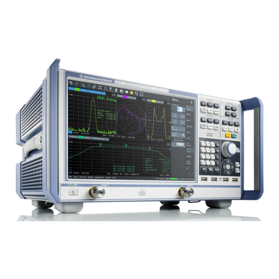
4.1 Front panel R&S ZNB The front panel of a R&S ZNB consists of the touchscreen with the diagrams and soft- tool panels (left side), the hardkey area (right side) and the test port area below. Brief explanations on the controls and connectors, the hardkey area and the rear panel can be found on the next pages. -
Page 30: Function Keys
® Instrument tour R&S ZNB/ZNBT Front panel R&S ZNB functions can be accessed and operated by tapping the control elements on the touch- screen. For an introduction to touchscreen operation, refer to Chapter 5.1, "Manual operation", on page 42. The following sections contain further useful information about manual control of the instrument. -
Page 31: Data Entry Keys
® Instrument tour R&S ZNB/ZNBT Front panel R&S ZNB The CHANNEL keys give access to the hardware-related (channel) settings. ● The [POWER BW AVG] settings define the power of the internal signal source, the IF bandwidth, and the sweep average. -
Page 32: Rotary Knob
® Instrument tour R&S ZNB/ZNBT Front panel R&S ZNB ● The function of the four unit keys depends on the data type of the active input field; Chapter 5.6, "Entering data", on page 59. – In numeric input fields, the G/n, M/μ, k/m or x1 keys multiply the entered value... -
Page 33: Standby Key
Shut down the instrument; see Chapter 3.7, "Switching the instrument on and off", on page 17. 4.1.7 Front panel connectors The test ports and four USB connectors are located on the front panel of the R&S ZNB. 4.1.7.1 Test ports Numbered connectors: ●... -
Page 34: Front Panel R&S Znbt
® Instrument tour R&S ZNB/ZNBT Front panel R&S ZNBT ● Use a torque wrench when screwing RF cables on the test port connectors. ● See also Chapter 3.5, "Considerations for test setup", on page 15. 4.1.7.2 USB connectors Four high-speed Universal Serial Bus connectors of type A (master USB). -
Page 35: Administrative Area
® Instrument tour R&S ZNB/ZNBT Front panel R&S ZNBT Numbered test port connectors: ● Type N female connectors for the R&S ZNBT8. Depending on the equipped port options there are 4, 8, 12, 16, 20 or 24 test ports. ●... -
Page 36: Rear Panel R&S Znb
Above the standby toggle switch some LEDs indicate various status information: ● [ERR]: operation state; if an error occurs, the LED lights up red; for more informa- tion on errors and troubleshooting see the R&S ZNB/ZNBT User Manual ● [LAN]: LAN error occurred ●... - Page 37 Instrument tour R&S ZNB/ZNBT Rear panel R&S ZNB 9 10 Figure 4-3: R&S ZNB rear view = 1st generation R&S ZNB (with latest CPU board LPW11) bottom = 2nd generation R&S ZNB (order nos. 1334.3330.xx) Getting Started 1316.0062.02 ─ 60...
- Page 38 IN / EXT TRIG REF OUT BNC output for the internal reference frequency of the R&S ZNB. Use this connector to synchronize other instruments to the analyzer. REF IN BNC input for an external reference frequency. Use this connector to synchronize the R&S ZNB to another device.
-
Page 39: Rear Panel R&S Znbt
"System Power Management Interface Specification". – 10 General Purpose Input/Output (GPIO) pins. Device Option R&S ZNB-B12 "Device Control" provides a PCIe and a Direct Control con- Control nector. The Direct Control interface enables direct connections between the VNA measure- ment bus and one or more extension devices, such as: ●... - Page 40 Fuse holder. For fuse replacement, see the corresponding section in the mainte- holder) nance chapter of the user manual. There is no such fuse on the R&S ZNB. RJ-45 connector to integrate the instrument to a Local Area Network, primarily for remote control purposes;...
- Page 41 ® Instrument tour R&S ZNB/ZNBT Rear panel R&S ZNBT Index Label Description REF IN BNC input for an external reference frequency. Use this connector to synchronize the R&S ZNBT to another device. SYSTEM Contains the removable system drive of the R&S ZNBT, containing all software DRIVE (including the operating system and the VNA application) and data.
-
Page 42: Operating The Instrument
Manual and remote control of the instrument In contrast to the R&S ZNB, the R&S ZNBT is primarily intended to be remote-control- led via the GPIB or LAN interface (see chapter 'Remote Control' in the user manual). - Page 43 ® Operating the instrument R&S ZNB/ZNBT Manual operation Figure 5-1: Function Keys Customizing the screen The contents of the screen and the size and position of many display and control ele- ments are not fixed. You can display or hide most elements. You can also drag and drop traces, info fields, and even the softtool panel to your preferred position;...
- Page 44 ® Operating the instrument R&S ZNB/ZNBT Manual operation 2. Activate the desired softtool tab, e.g. "Z←Sij". 3. Select a control element, e.g. "Z←S11". The diagram immediately reflects your selection. The active trace shows the mea- surement results for the selected measured quantity.
- Page 45 ® Operating the instrument R&S ZNB/ZNBT Manual operation Using the menu bar The menu bar at the bottom of the application screen provides alternative access to all instrument functions. To repeat the measured quantity selection described above, ► Select Trace – [Meas] > "Z←Sij" > "Z←S11".
- Page 46 ® Operating the instrument R&S ZNB/ZNBT Manual operation 2. Select "S-Parameter" to open the "Meas" > "S-Params" softtool tab. 3. Select "Z←Sij" > "Z←S11". Getting Started 1316.0062.02 ─ 60...
-
Page 47: Control Elements Of The Application Window
® Operating the instrument R&S ZNB/ZNBT Control elements of the application window 5.2 Control elements of the application window The application window of the analyzer provides all control elements for the measure- ments and contains the diagrams for the results. There are several alternative ways for accessing an instrument function: ●... -
Page 48: Toolbar
Toggle other measurements (except the active trace) OFF|ON ● Open the "METAS Reconnection" dialog This button is only visible if, option R&S ZNB/ZNBT-K50 "Measure- ment Uncertainty Analysis"" is installed. It is only enabled, if a METAS calibration is active. You can hide the toolbar using System – [Display] > "View Bar". -
Page 49: Softtools
(R&S ZNB only) or a mouse. A short tap (left mouse click) expands a menu or sub- menu. If a menu command has no submenu assigned, a short tap (left mouse click) opens a dialog or directly activates the menu command. -
Page 50: Menu Structure
® Operating the instrument R&S ZNB/ZNBT Control elements of the application window ● The "Trace" menu provides all trace settings, the limit check settings, and the marker functions including marker search. ● The "Channel" menu provides all channel settings and activates, modifies or stores different channels. -
Page 51: Hardkey Panel
The (virtual) "Hard Key" panel provides on-screen access to the function keys (plus the [Undo] and [Redo] key) that are available at the front panel of a R&S ZNB. Most of the function keys open a related softtool. For a short description, refer to section Chap- ter 4.1.2, "Function... -
Page 52: Touchscreen Gestures
® Operating the instrument R&S ZNB/ZNBT Touchscreen gestures The progress bar also shows when the R&S ZNB/ZNBT prepares a sweep with new channel settings ● the "EXT REF" symbol, if an external reference clock is used for synchronization ● a symbol for redefined S-parameters, if the physical ports have been redefined ●... - Page 53 Move two fingers apart on the display (spread) or move two fingers together on the dis- play (pinch). On the R&S ZNB/ZNBT, these gestures take effect for diagrams only. The effect depends on the current zoom mode (see Chapter 5.7, "Scaling diagrams",...
-
Page 54: Working With Dialogs
® Operating the instrument R&S ZNB/ZNBT Working with dialogs While "Zoom Select" is active (toolbar icon or softtool button is toggled on), spread- ing and pinching is disabled. You can only select a rectangular area (using one fin- ger) then. -
Page 55: Handling Diagrams, Traces, And Markers
® Operating the instrument R&S ZNB/ZNBT Handling diagrams, traces, and markers All dialogs are operated in a similar way. ● To open a dialog, select a softtool button with three dots appearing in its label (e.g. "Start... (Manual)"). ● The title bar of each dialog contains some convenience functions: –... -
Page 56: Adding New Traces And Diagrams
For further reference Refer to chapter "Concepts and Features" in the R&S ZNB/ZNBT Help or in the User Manual to learn more about traces, channels, and screen elements. 5.5.1 Adding new traces and diagrams A new trace is required if you want to measure and display an additional quantity. -
Page 57: Adding New Markers
3. In the dialog box that is opened when you release the "New Trace" icon, select the S-parameter to be measured. For a four-port analyzer: The R&S ZNB/ZNBT generates a new trace for the selected S-parameter. Alternative control elements To measure a different quantity, select Trace – [Meas]. Drag and drop a softkey repre- senting a measured quantity to create a trace. -
Page 58: Deleting Display Elements
® Operating the instrument R&S ZNB/ZNBT Handling diagrams, traces, and markers Active trace, alternative control elements The trace line of the active trace in the upper part of the diagram is highlighted. If the diagram contains several traces, first activate the target trace, then add the marker. -
Page 59: Using Drag And Drop
However, there are various other ways to enter data. 5.6.1 Using front panel keys On a R&S ZNB you can use the keys in the data entry keypad to enter numbers, units, and characters. Getting Started 1316.0062.02 ─ 60... - Page 60 ® Operating the instrument R&S ZNB/ZNBT Entering data To enter a numeric value: 1. Select a numeric data input field to activate it. 2. Press the data entry keys. ● Use [0] to [9] to enter the corresponding numbers. ●...
-
Page 61: Using The Numeric Editor
® Operating the instrument R&S ZNB/ZNBT Entering data 5.6.2 Using the numeric editor The "Numeric Editor" is a tool for convenient entry and modification of numeric values. It is available for all numeric input fields in the analyzer GUI. Operation with touchscreen or mouse: 1. -
Page 62: Using The Windows ® On-Screen Keyboard
® Operating the instrument R&S ZNB/ZNBT Entering data 1. Activate a character data input field in a softtool or a dialog. 2. Double-tap/click the input field to open the on-screen keyboard. 3. Select character buttons to compose the input string. -
Page 63: Scaling Diagrams
® Operating the instrument R&S ZNB/ZNBT Scaling diagrams 5.7 Scaling diagrams The analyzer provides various tools for customizing the diagrams and for setting the sweep range. Choose the method that is most convenient for you. 5.7.1 Using the graphical zoom The graphical zoom function magnifies a rectangular portion of the diagram (zoom win- dow) to fill the entire diagram area. -
Page 64: Setting The Sweep Range
® Operating the instrument R&S ZNB/ZNBT Scaling diagrams Use the "Zoom Reset" icon to restore the original diagram. Alternatively, you can drag and drop the "Zoom" label from the additional channel info line onto the toolbar but- ton. Alternative settings ●... -
Page 65: Reference Value And Position
® Operating the instrument R&S ZNB/ZNBT Scaling diagrams To change the sweep range of the active channel, use one of the following methods: ● Use the [Start], [Stop], [Center], and [Span] function keys from the Stimulus sec- tion. ● Double-tap (with a mouse: double-click) the "Start" or "Stop" label in the channel list. -
Page 66: Circular Diagrams
® Operating the instrument R&S ZNB/ZNBT Scaling diagrams ● Select "Auto Scale Trace" or "Auto Scale Diagram" from the "Trace" > "Scale" menu. 5.7.5 Circular diagrams The radial scale of a circular diagram ("Polar", "Smith" or "Inverted Smith") can be changed with a single linear parameter, the "Ref Value". -
Page 67: Enlarging A Diagram
® Operating the instrument R&S ZNB/ZNBT Scaling diagrams Set "Start" and "Stop" values in the diagram: 1. Create two normal markers, e.g. the markers "Mkr 1" (default label "M1") and "Mkr 2" (default label "M2"). Chapter 5.5.2, "Adding new markers", on page 57. - Page 68 ® Operating the instrument R&S ZNB/ZNBT Scaling diagrams Use the context menu of the diagram, the System – [Display] key or the "Display" menu to access the display settings. Getting Started 1316.0062.02 ─ 60...
-
Page 69: Performing Measurements
ZNB/ZNBT Transmission S-parameter measurement 6 Performing measurements This chapter takes you through a sample session with a R&S ZNB/ZNBT network ana- lyzer and describes basic operation tasks. Prerequisite The instrument is set up, connected to the mains system, and started up as described Chapter 3, "Preparing for... - Page 70 R&S ZNB/ZNBT Transmission S-parameter measurement test ports. It is recommended that you preset the R&S ZNB/ZNBT to start from a well- defined instrument state. 1. Connect the DUT between test ports 1 and 2 of the network analyzer as shown above.
-
Page 71: Selecting The Sweep Range And Other Parameters
Chapter 5.6.2, "Using the numeric editor", on page 61). Tip: If you use the data entry keys at the front panel for data entry (R&S ZNB only), type [1][.][7][7] and terminate the entry with the [G/n] key. Refer to Chapter 5.6, "Entering data",... -
Page 72: Calibrating The Instrument
With a single Through, it is possible to perform a transmission normalization, compen- sating for a frequency-dependent attenuation and phase shift in the signal paths. Due to the R&S ZNB/ZNBT's calibration wizard, calibration is a straightforward, guided process. 1. Replace the DUT by the Through standard of your calibration kit. Make sure to dis- connect all calibration units. - Page 73 ® Performing measurements R&S ZNB/ZNBT Transmission S-parameter measurement Tip: For a R&S ZNBT with more than 4 ports, the graphical port representation is replaced by a generic port list. The selection logic is unchanged. 4. Select "Next" to proceed to the next page of the "Calibration Setting" wizard.
-
Page 74: Evaluating Data
Through standard. The similarity of real and expected traces indicates that the Through standard has been properly connected. After the R&S ZNB/ZNBT has completed the calibration sweep and calculated the correction data, the "Apply" button is enabled. -
Page 75: Saving And Printing Data
® Performing measurements R&S ZNB/ZNBT Transmission S-parameter measurement This places marker "M1" to its default position (center of the sweep range). A marker symbol (triangle) appears on the trace, a marker info field in the upper right corner of the diagram. The marker info field displays the stimulus value (frequency) and response value (magnitude of the transmission coefficient converted to a dB value) at the marker position. -
Page 76: Reflection S-Parameter Measurement
® Performing measurements R&S ZNB/ZNBT Reflection S-parameter measurement Data transfer is made easier if external accessories are connected to the analyzer or if the instrument is integrated into a LAN. Refer to Chapter 3.11, "Connecting external accessories", on page 21, and Chapter 3.12, "Remote operation in a... - Page 77 ® Performing measurements R&S ZNB/ZNBT Reflection S-parameter measurement You can also use the basic transmission test setup, e.g. if you want to measure reflection and transmission parameters in parallel. ● The analyzer provides special calibration types for reflection measurements. Use the calibration wizard and select an appropriate type.
-
Page 78: Firmware Installation
® Firmware installation R&S ZNB/ZNBT 7 Firmware installation Upgrade versions of the analyzer firmware are supplied as single executable setup files (*.exe). 64-bit only Since version 3.00 of the analyzer firmware, 32-bit Windows is no longer supported. Only 64-bit firmware is available. -
Page 79: Contacting Customer Support
® Contacting customer support R&S ZNB/ZNBT 8 Contacting customer support Technical support – where and when you need it For quick, expert help with any Rohde & Schwarz product, contact our customer sup- port center. A team of highly qualified engineers provides support and works with you to find a solution to your query on any aspect of the operation, programming or applica- tions of Rohde &... -
Page 80: Index
Front panel analyzer ..............61 LED controls ............... 36 Windows ..............62 Mini display ..............35 Operating system .............. 19 R&S ZNB ..............29 Option R&S ZNBT ..............34 R&S ZN-B12 ............... 39 USB ................35 R&S ZN-B14 ............... 39 Front panel keys .............. - Page 81 Sweep range setting ............64 R&S ZNB-B10 ............. 39 SYSTEM ................31 R&S ZNB-B81 ............. 39 R&S ZNBT-B4 ............. 18 Option R&S ZNB-B19 ............38 Option R&S ZNBT-B10 ............. 41 Test port ..............33, 34 Option R&S ZNBT-B12 ............. 41 Title bar ................47 Option R&S ZNBT-B19 .............
Need help?
Do you have a question about the ZNB and is the answer not in the manual?
Questions and answers